
Related Manuals for ABB PowerValue 31/11 T 10 kVA


Summary of Contents for ABB PowerValue 31/11 T 10 kVA
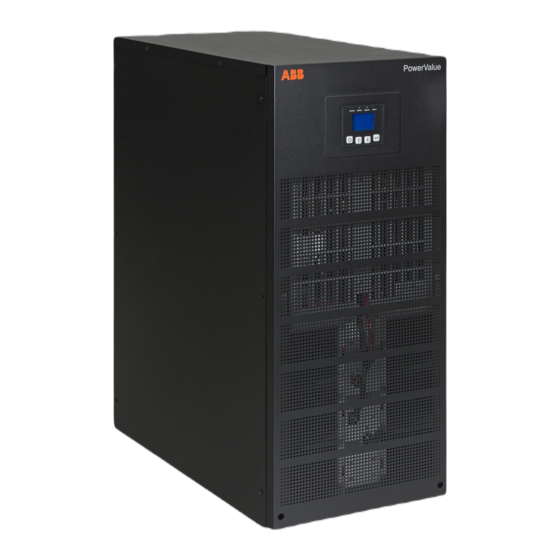
- Page 1 4NWP100559R0001_OPM_ABB_PVA31-11-T_10-20kVA_EN_140626 PowerValue 31/11 T 10/20 kVA User Manual © Copyright 2014 ABB, All rights reserved. 4NWP100559R0001_OPM_ABB_PVA31-11-T_10-20kVA_EN_140626 Page 1/37 ABB Modifications reserved...
- Page 2 This page left intentionally blank 4NWP100559R0001_OPM_ABB_PVA31-11-T_10-20kVA_EN_140626 Page 2/37 ABB Modifications reserved...
-
Page 3: Foreword
A terminal to which or from which a direct current or voltage (DC) may be applied or supplied Battery Power On, Idle or shutdown the UPS Overload indication Recycle Do not dispose with ordinary trash 4NWP100559R0001_OPM_ABB_PVA31-11-T_10-20kVA_EN_140626 Page 3/37 ABB Modifications reserved... -
Page 4: Table Of Contents
5.2 Operating Mode ......................24 5.3 UPS Start-up and Shutdown ..................25 5.3.1 UPS start-up ......................25 5.3.2 UPS Shutdown ......................25 5.3.3 Parallel UPS system ....................26 5.4 UPS Operation ........................27 5.4.1 Changing the operating-mode ..................27 5.4.2 Navigation........................27 4NWP100559R0001_OPM_ABB_PVA31-11-T_10-20kVA_EN_140626 Page 4/37 ABB Modifications reserved... - Page 5 6.3.2 AS400 Dry Contact card ....................33 6.3.3 Monitoring Software ....................33 TROUBLESHOOTING ....................34 7.1 Fault identification and rectification ................34 7.1.1 Troubleshooting without an error message ..............34 7.1.2 Troubleshooting based on error message ..............34 TECHNICAL SPECIFICATION ................... 36 4NWP100559R0001_OPM_ABB_PVA31-11-T_10-20kVA_EN_140626 Page 5/37 ABB Modifications reserved...
-
Page 6: Safety Instructions
EN ISO 9001 of Quality Management Systems. The marking shows the conformity to the EEC Directive by means of the application of the following standards in accordance with the specifications of the harmonized standards: • 2006/95/EC Low voltage directive. • 2004/108/EC Electromagnetic Compatibility directive (EMC). 4NWP100559R0001_OPM_ABB_PVA31-11-T_10-20kVA_EN_140626 Page 6/37 ABB Modifications reserved... -
Page 7: Inquiries
To disconnect completely the UPS, follow the instructions in Section 5.3.2. Indiscriminate operation of switches may cause output loss or damage to equipment. Ensure that no liquid or other foreign objects enter the UPS. 4NWP100559R0001_OPM_ABB_PVA31-11-T_10-20kVA_EN_140626 Page 7/37 ABB Modifications reserved... -
Page 8: Maintenance
NEVER DISPOSE BATTERIES ON FIRE AS THEY MAY EXPLODE. DO NOT OPEN OR MUTILATE THE BATTERIES. WARNING! RELEASED ELECTROLYTE IS HARMFUL TO THE SKIN AND EYES. Discard appropriately the UPS, battery module and batteries and follow your local laws and regulations. 4NWP100559R0001_OPM_ABB_PVA31-11-T_10-20kVA_EN_140626 Page 8/37 ABB Modifications reserved... -
Page 9: General Characteristics
Input breaker Back feed control Fans Relay card slot EPO contact RS232 port USB port Parallel port Network interface card slot Maintenance switch Figure 3: Rear view of PowerValue 31/11 T 10 and 20 kVA 4NWP100559R0001_OPM_ABB_PVA31-11-T_10-20kVA_EN_140626 Page 9/37 ABB Modifications reserved... -
Page 10: External Battery Cabinet Front View
UPS support Figure 4: Front view of external battery cabinet 3.1.4 External battery cabinet rear view Number Description Ventilation inlets Fuse holder Connection terminals Wheels UPS support Figure 5: Rear view of external battery cabinet 4NWP100559R0001_OPM_ABB_PVA31-11-T_10-20kVA_EN_140626 Page 10/37 ABB Modifications reserved... -
Page 11: Installation
5. Install the side mounting brackets (used for shipping) back to the unit to ensure higher stability of the UPS. If desired, the UPS can also be fixed to the floor with M8 bolts. 4NWP100559R0001_OPM_ABB_PVA31-11-T_10-20kVA_EN_140626 Page 11/37 ABB Modifications reserved... -
Page 12: Ups Storage
PHYSICAL INJURY OR DEATH MAY HAPPEN, DAMAGE TO THE UPS OR TO THE LOAD EQUIPMENT MAY OCCUR IF THESE INSTRUCTIONS ARE IGNORED To ensure correct operation of the UPS and batteries, it is necessary to provide the mains cables with appropriate fuse protection. 4NWP100559R0001_OPM_ABB_PVA31-11-T_10-20kVA_EN_140626 Page 12/37 ABB Modifications reserved... -
Page 13: Connections
Max section: 13 mm Max section: 25 mm AC contactor of minimally 100A rating, e.g. a three phase contactor of 3* 40A with the poles wired together (e.g. ABB Back feed Bypass protection (M2) AF-26) Control coil rated according to bypass supply. - Page 14 This is very important to prevent access terminal and the load. The breaker should have to energized cables and metal forks. a leakage current protective function according to the UPS voltage and current ratings. 4NWP100559R0001_OPM_ABB_PVA31-11-T_10-20kVA_EN_140626 Page 14/37 ABB Modifications reserved...
- Page 15 3. Connect the M2 cable provided with the UPS (refer to section 4.2.2.1) between terminal M2 and the fork (use the M5 screw provided in the fork connection. 4. Connect the phase cable from the mains to the 3-pin fork. Figure 8: Single feed (11) wiring diagram 4NWP100559R0001_OPM_ABB_PVA31-11-T_10-20kVA_EN_140626 Page 15/37 ABB Modifications reserved...
- Page 16 1. Connect the neutral cables to the neutral terminals (mains 1 and mains 2). 2. Connect the 3-pole fork provided with the UPS between terminals L1, L2 and L3. Figure 9: 3-pole fork installation 3. Connect the phase cables accordingly. Figure 10: Dual feed (11) wiring diagram 4NWP100559R0001_OPM_ABB_PVA31-11-T_10-20kVA_EN_140626 Page 16/37 ABB Modifications reserved...
- Page 17 UPS. Isolate and do not connect neutral of mains 1 as there is a possibility bypass current would return through and overload the smaller cable of mains 1. 2. Connect the phase cables to L1, L2, L3 and M2. Figure 13: Dual feed (31) wiring diagram 4NWP100559R0001_OPM_ABB_PVA31-11-T_10-20kVA_EN_140626 Page 17/37 ABB Modifications reserved...
- Page 18 7. It is recommended that the distance between the UPSs in parallel and the breaker panel is lower than 20 meters. The difference in length between the wires of the input and output of the UPSs is required to be less than 20%. Figure 14: Terminal block wiring diagram in parallel configuration 4NWP100559R0001_OPM_ABB_PVA31-11-T_10-20kVA_EN_140626 Page 18/37 ABB Modifications reserved...
-
Page 19: Batteries
To replace, reduce or increase the amount of batteries, connect the batteries as indicated in Figure 16. Connect the terminals to their matching color terminals. 1x24 batteries 2x24 batteries Figure 16: Internal batteries connections 4NWP100559R0001_OPM_ABB_PVA31-11-T_10-20kVA_EN_140626 Page 19/37 ABB Modifications reserved... -
Page 20: External Battery Cabinets
Figure 17. Remove the protecting cover of the back feed Install the back terminals on the back of the UPS and install a contactor (see Table 1 for dimensioning). feed control wire according to relevant wiring rules. 4NWP100559R0001_OPM_ABB_PVA31-11-T_10-20kVA_EN_140626 Page 20/37 ABB Modifications reserved... -
Page 21: Emergency Power Off (Epo)
Any optional accessories are mounted in their installed location and properly wired. Summary alarms and/or building alarms are wired appropriately. (Optional) Start-up and operational checks performed by authorized service personnel. All network connections are completed. 4NWP100559R0001_OPM_ABB_PVA31-11-T_10-20kVA_EN_140626 Page 21/37 ABB Modifications reserved... -
Page 22: Operation
UPS is turning ON Online mode Battery mode ECO mode Battery test mode Fault mode Warning Legend: A: LED flashing B: constantly lightened C: lightened circularly D: depends on the failure/warning Table 3: LEDs indication 4NWP100559R0001_OPM_ABB_PVA31-11-T_10-20kVA_EN_140626 Page 22/37 ABB Modifications reserved... -
Page 23: Selection Keys
- Battery and charger status (including battery voltage, charge level and charger status) - Current runtime information If the user does not press any keys for more than 15 minutes, the UPS leads to the status display. Figure 20: Main UPS screen 4NWP100559R0001_OPM_ABB_PVA31-11-T_10-20kVA_EN_140626 Page 23/37 ABB Modifications reserved... -
Page 24: Operating Mode
90% of its nominal power capacity in order to stop alarming. Battery test UPS is performing a battery test. Battery disconnected The battery is disconnected or defective. The UPS alarm sounds. 4NWP100559R0001_OPM_ABB_PVA31-11-T_10-20kVA_EN_140626 Page 24/37 ABB Modifications reserved... -
Page 25: Ups Start-Up And Shutdown
3s and the output power will be immediately cut-off. 2. After a few seconds, the display will shut down and the output voltage will be removed from the UPS output terminal. 4NWP100559R0001_OPM_ABB_PVA31-11-T_10-20kVA_EN_140626 Page 25/37 ABB Modifications reserved... -
Page 26: Parallel Ups System
9. Set the main maintenance switch or static switch from “BPS” to “UPS” and screw the maintenance cover plate back to the UPS. 1. Press the power-on button of one UPS. Each UPS will start-up and all UPSs will run in parallel in online mode. 4NWP100559R0001_OPM_ABB_PVA31-11-T_10-20kVA_EN_140626 Page 26/37 ABB Modifications reserved... -
Page 27: Ups Operation
. In this menu, the last 50 events, alarms and faults occurred in the UPS are displayed. The alarms are indicated by the corresponding event code and operating time of UPS when the event occurred. To navigate through the events and alarms, press or . 4NWP100559R0001_OPM_ABB_PVA31-11-T_10-20kVA_EN_140626 Page 27/37 ABB Modifications reserved... - Page 28 1s. Then scroll up or down to modify the parameters. To confirm the selection, press for more than 1s. gives an overview on how to navigate on Figure 23 the control menu. 4NWP100559R0001_OPM_ABB_PVA31-11-T_10-20kVA_EN_140626 Page 28/37 ABB Modifications reserved...
- Page 29 1s in the Settings menu to enter the sub-menus. To modify a parameter, press for less than 1 second and scroll up or down. To confirm the selection press this same button for more than 1 second. 4NWP100559R0001_OPM_ABB_PVA31-11-T_10-20kVA_EN_140626 Page 29/37 ABB Modifications reserved...
- Page 30 - When enabled, short circuit will last for 4s before cutting off the output. If short circuit is Short circuit removed during this time, the UPS will enabled/disabled disabled clearance continue to run normally. - When disabled, short circuit will only last 4NWP100559R0001_OPM_ABB_PVA31-11-T_10-20kVA_EN_140626 Page 30/37 ABB Modifications reserved...
- Page 31 ***Ensure the real battery quantity is same as indicated in the settings not to damage the batteries. Example: Setting the rated output voltage value ( Figure 26 ). Figure 26: Setting rated output voltage value 4NWP100559R0001_OPM_ABB_PVA31-11-T_10-20kVA_EN_140626 Page 31/37 ABB Modifications reserved...
-
Page 32: Communication
UPS through internet / intranet. The accessories below can be installed in any of the intelligent slots. SNMP Card - SNMP, HTTP and monitoring capabilities through a Web browser interface. AS400 Card - AS400 card for AS400 communication protocol. 4NWP100559R0001_OPM_ABB_PVA31-11-T_10-20kVA_EN_140626 Page 32/37 ABB Modifications reserved... -
Page 33: Installing A Serial Network Management Card (Optional)
6.3.3 Monitoring Software ABB UPS can be monitored through a software that allows the user to monitor the UPS. The software provides a remote and safe shutdown for multi-client systems in case of absence of power in the output of the UPS. Instructions on how to install the software are provided with the network management cards. -
Page 34: Troubleshooting
DC BUS short circuited UPS internal fault Contact UPS supplier. Alarm code:24 DC BUS softstart failure UPS internal fault Contact UPS supplier. Alarm code:25 INV over-voltage UPS internal fault Contact UPS supplier. Alarm code:32 4NWP100559R0001_OPM_ABB_PVA31-11-T_10-20kVA_EN_140626 Page 34/37 ABB Modifications reserved... - Page 35 2. Date on which the problem occurred 3. LCD/LED display information, buzzer alarm status 4. Mains power condition, load type and capacity, environment temperature, ventilation condition 5. Information on external batteries (battery capacity, quantity) 4NWP100559R0001_OPM_ABB_PVA31-11-T_10-20kVA_EN_140626 Page 35/37 ABB Modifications reserved...
-
Page 36: Technical Specification
IEC/EN 62040-3 Manufacturing ISO 9001:2008, ISO 14001:2004 WEIGHT, DIMENSIONS Weight 56 kg 117 kg 177 kg 66 kg 187 kg Dimensions WxHxD 350*890*712 350*890*712 350*890*712 350*890*712 350*890*172 *Technical specifications are subject to change without notice 4NWP100559R0001_OPM_ABB_PVA31-11-T_10-20kVA_EN_140626 Page 36/37 ABB Modifications reserved... - Page 37 4NWP100559R0001_OPM_ABB_PVA31-11-T_10-20kVA_EN_140626 Page 37/37 ABB Modifications reserved...