Table of Contents
Advertisement
Quick Links
Power Monitoring Device
and
Class A Power Quality
Recorder
SICAM Q100
7KG95xx
V2.00
Device Manual
E50417-H1040-C522-A4
Preface
Open Source Software
Contents
User Information
Overview
Device Design
Measured Quantities and Recording
Energy Management
Getting Started
Connection Principle
Operation at Use of a PC
Operation at Use of the Display
Time Synchronization
Maintenance, Storage, Transport
Failures and LED Indications
Technical Data
Operational Indications
Operating Parameters
Glossary
Index
1
2
3
4
5
6
7
8
9
10
11
12
13
14
15
Advertisement
Table of Contents

Related Manuals for Siemens SICAM Q100


Summary of Contents for Siemens SICAM Q100
- Page 1 Contents Power Monitoring Device User Information Overview Class A Power Quality Device Design Recorder Measured Quantities and Recording SICAM Q100 Energy Management 7KG95xx Getting Started V2.00 Connection Principle Operation at Use of a PC Device Manual Operation at Use of the Display...
- Page 2 SIEMENS AG. An unauthorized use is illegal. Siemens AG reserves the right to revise this document from time to All other designations in this document can be trademarks whose time.
-
Page 3: Preface
This manual is intended for project engineers, commissioning and operating personnel in electrical systems and power plants. Scope of Validity of this Manual This manual is valid for the Power Monitoring Device and Class A Power Quality Recorder SICAM Q100 7KG95xx. Further Support For any questions concerning your system, please contact your Siemens representative. - Page 4 Follow all advice instructions to prevent damage to property. NOTE is important information about the product, the handling of the product, or the part of the documentation in question to which special attention must be paid. SICAM Q100, 7KG95xx, Device Manual E50417-H1040-C522-A4, Edition 03.2018...
- Page 5 Equipment with exposed current transformer circuits must not be operated. Prior to disconnecting the equipment, ensure that the current transformer circuits are short-circuited. • The limit values stated in the document may not be exceeded. This must also be considered during testing and commissioning. SICAM Q100, 7KG95xx, Device Manual E50417-H1040-C522-A4, Edition 03.2018...
- Page 6 IEC 60417-5032 Direct and alternating current IEC 60417-5033 Three-phase alternating current Earth (ground) terminal IEC 60417-5017 Protective conductor terminal IEC 60417-5019 Caution, risk of electric shock Caution, risk of danger ISO 7000-0434 SICAM Q100, 7KG95xx, Device Manual E50417-H1040-C522-A4, Edition 03.2018...
- Page 7 (Lowvoltage Directive 2006/95/EC - valid until April 19th, 2016; Lowvoltage Directive 2014/35/ EU - valid as of April 20th, 2016). This conformity has been established by means of tests conducted by Siemens AG according to the Council Directive in agreement with the generic standards EN 61000-6-2 and EN 61000-6-4 for the EMC directives, and with the standard EN 61010-1 for the low-voltage directive.
- Page 8 SICAM Q100, 7KG95xx, Device Manual E50417-H1040-C522-A4, Edition 03.2018...
-
Page 9: Open Source Software
The Open Source Software is licensed royalty-free. Insofar as the applicable Open Source Software License Conditions provide for it you can order the source code of the Open Source Software from your Siemens sales contact - against payment of the shipping and handling charges - for a period of at least 3 years since purchase of the Product. - Page 10 SICAM Q100, 7KG95xx, Device Manual E50417-H1040-C522-A4, Edition 03.2018...
-
Page 11: Table Of Contents
Unpacking, Inspecting the Delivery, Installing, and Changing the Battery ..... . 90 SICAM Q100, 7KG95xx, Device Manual E50417-H1040-C522-A4, Edition 03.2018... - Page 12 Using SICAM Q100 in the Power Systems IT, TT, and TN ......
- Page 13 General Inspection ............. . . 308 SICAM Q100, 7KG95xx, Device Manual...
- Page 14 Transient Detection ............356 SICAM Q100, 7KG95xx, Device Manual...
- Page 15 Index ................. . 375 SICAM Q100, 7KG95xx, Device Manual...
- Page 16 SICAM Q100, 7KG95xx, Device Manual E50417-H1040-C522-A4, Edition 03.2018...
-
Page 17: User Information
6 tariffs. The device is used on all voltage levels of power supply systems. SICAM Q100 is used in 1-phase systems and in 3-wire and 4-wire systems (with neu- tral conductor). The device is mainly used by power utilities but also in other industrial and commercial sectors. - Page 18 Energy Management As part of the energy management, SICAM Q100 records load profiles according to the Fixed Block and Rolling Block method for all power quantities. Additionally, it is possible to calculate up to 6 tariffs (TOU = Time of Use).
-
Page 19: Overview
2 Overview Overview Device Versions Ordering Information, Scope of Delivery and Accessories SICAM Q100, 7KG95xx, Device Manual E50417-H1040-C522-A4, Edition 03.2018... -
Page 20: Device Versions
2 Overview 2.1 Device Versions Device Versions SICAM Q100 is a multifunctional device for the detection, calculation, recording, evaluation, display, and trans- mission of measured electrical quantities with the following properties: Consistent Device Properties All devices consistently feature the following properties: •... - Page 21 CE certification UL certification • Evaluations Output of power quality reports Variants SICAM Q100 is available in different variants: • Communication via Ethernet Only Modbus TCP protocol Modbus TCP protocol or IEC 61850 server protocol •...
-
Page 22: Ordering Information, Scope Of Delivery And Accessories
2.2 Ordering Information, Scope of Delivery and Accessories Ordering Information, Scope of Delivery and Accessories Ordering Information Use the following ordering code to order SICAM Q100 devices: Description Order No. / MLFB Power Monitoring Device and Power Quality Recorder, Class A... - Page 23 2.2 Ordering Information, Scope of Delivery and Accessories Scope of Delivery The delivery comprises the following components depending on the ordering code: • SICAM Q100 according to ordering code (see Figure 2-2) • Battery (insulated in the battery compartment of the device) •...
- Page 24 Ethernet Patch Cable (Double Shielded (SFPT), LAN Connector Plugs on Both Sides) Cable Length Order No. 0.5 m 7KE6000-8G-D00-0AA5 1.0 m 7KE6000-8G-D00-1AA0 2.0 m 7KE6000-8G-D00-2AA0 3.0 m 7KE6000-8G-D00-3AA0 5.0 m 7KE6000-8G-D00-5AA0 10.0 m 7KE6000-8G-D01-0AA0 15.0 m 7KE6000-8G-D01-5AA0 20.0 m 7KE6000-8G-D02-0AA0 SICAM Q100, 7KG95xx, Device Manual E50417-H1040-C522-A4, Edition 03.2018...
-
Page 25: Device Design
3 Device Design Device Design Mechanical Design Display and Softkeys SICAM Q100, 7KG95xx, Device Manual E50417-H1040-C522-A4, Edition 03.2018... -
Page 26: Mechanical Design
A lithium battery is located under the removable cover of the battery compartment. SICAM Q100 devices can also contain a D-sub connector plug as RS485 interface (see Figure 3-1) as shown in the ordering information (see Chapter 2.2). -
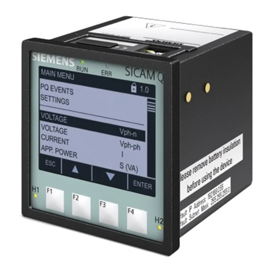
Page 27: Display And Softkeys
The IP address and the standard subnet mask are imprinted on the side panel of the device (see Figure 3-1). Chapter 9 gives a detailed description of the softkey functions. SICAM Q100, 7KG95xx, Device Manual E50417-H1040-C522-A4, Edition 03.2018... - Page 28 3 Device Design 3.2 Display and Softkeys SICAM Q100, 7KG95xx, Device Manual E50417-H1040-C522-A4, Edition 03.2018...
-
Page 29: Measured Quantities And Recording
4 Measured Quantities and Recording Measured Quantities and Recording Power Quality Measuring System and Recording System Measured Quantities Display of Measured Quantities SICAM Q100, 7KG95xx, Device Manual E50417-H1040-C522-A4, Edition 03.2018... -
Page 30: Power Quality Measuring System And Recording System
Power Quality Measuring System and Recording System 4.1.1 Measuring System SICAM Q100 devices measure the power quality according to IEC 61000-4-30 in 1-phase or multi-phase distribution systems. The basic measuring interval for determining the values for mains voltage, harmonics of mains voltage, and mains voltage unbalance is 10 cycles for 50 Hz distribution systems or 12 cycles for 60 Hz distribution systems. -
Page 31: Transients
100 µs at 50 Hz (80 µs at 60 Hz). The following data and values are determined during the evaluation of the transients in SICAM Q100 and listed in the window Transient detection (see Chapter 8.4.2.7): •... -
Page 32: Mains Signalling Voltage
Mains Signalling Voltage Mains signalling voltage (MSV) measurement is performed according to IEC 61000-4-30. SICAM Q100 detects mains singalling frequencies from 100 Hz to 3 kHz. The threshold for detection and capture is from 1 % up to 15 % of Udin. -
Page 33: Rapid Voltage Change
The threshold of RVC detection is configurable from 1 % up to 6 % of Udin. The following data and values are determined during the evaluation of the rapid voltage change in SICAM Q100 and listed in the tab Rapid Voltage Change (see Chapter 8.4.2.1): •... -
Page 34: Harmonic Power And Harmonic Angles
Harmonic Directions SICAM Q100 measures harmonics of currents, voltages, and powers up to the 63rd order. Measuring is done according to the standard IEC 61000-4-7. The following values are given for each harmonic: •... - Page 35 The prevailing ratio (PR) is proposed to indicate how much the harmonic measurements vary in the complex plane. NOTE You find further information to this feature in the application note: www.siemens.com/powerquality. SICAM Q100, 7KG95xx, Device Manual E50417-H1040-C522-A4, Edition 03.2018...
-
Page 36: Recording Of Measured Quantities And Events
4.1 Power Quality Measuring System and Recording System 4.1.7 Recording of Measured Quantities and Events 4.1.7.1 Power Quality Recorder Types SICAM Q100 provides different recording options to monitor and analyze the power quality and for the load profile. Table 4-2 Recording Measured Values... - Page 37 Rolling Block of electric power For detailed information on the load profile, refer to chapter 5. The respective measuring interval of the recording is time-stamped to enable a correct time evaluation. SICAM Q100, 7KG95xx, Device Manual E50417-H1040-C522-A4, Edition 03.2018...
- Page 38 Changes on Trend (½ ) Recorder Synchronization Mains Signalling Mains Voltage Signalling Voltage Magnitude Voltage Recorder Harmonics Interharmonics Unbalance Measurement Recorder Current Power , Pf, Load Profile Figure 4-5 Block Diagram of Recorders SICAM Q100, 7KG95xx, Device Manual E50417-H1040-C522-A4, Edition 03.2018...
-
Page 39: Measured Quantities
(Delta) (Star) PQ Values for PQ Values for ph-N ph-ph Measured 1-phase Circuit Quantity System Alternating Voltage a, b, c Vph-n/3 Vavg Vph-ph/3 Vph-ph/3 Vavg Neg.seq.co mp.V Zero seq.comp.V SICAM Q100, 7KG95xx, Device Manual E50417-H1040-C522-A4, Edition 03.2018... - Page 40 Zero a, b, c seq.comp.I Active Power Factor cos (a) cos (b) cos (c) cos cos ph/3 a, b, c Power Factor PFph/3 a, b, c Phase Angle UIa SICAM Q100, 7KG95xx, Device Manual E50417-H1040-C522-A4, Edition 03.2018...
- Page 41 Measured 1-phase Circuit Quantity System UIb UIc UI UIph/3 a, b, c ab V bc V ca V ab I bc I ca I Frequency (System Table freq.) 4-21 SICAM Q100, 7KG95xx, Device Manual E50417-H1040-C522-A4, Edition 03.2018...
- Page 42 = 1: Fundamental Harmonics, Voltage, Magnitude H_Va-x H_Vb-x H_Vc-x H_Vab-x H_Vbc-x H_Vca-x Interharmonics, Voltage, Magnitude HI_Va-y HI_Vb-y HI_Vc-y H_Vab-y H_Vbc-y H_Vca-y Harmonics, Current, Magnitude H_Ia-x H_Ib-x H_Ic-x Interharmonics, Current, Magnitude HI_Ia-y SICAM Q100, 7KG95xx, Device Manual E50417-H1040-C522-A4, Edition 03.2018...
- Page 43 = 1 to 49) Circuit System x = 1: Fundamental HI_Ib-y HI_Ic-y THDS, Voltage THDS_Va THDS_Vb THDS_Vc THDS_Vab THDS_Vbc THDS_Vca THDS, Current THDS_Ia THDS_Ib THDS_Ic TDD, Current TDD_Ia TDD_Ib TDD_Ic K-Factor, Voltage K-Factor_Va K-Factor_Vb K-Factor_Vc SICAM Q100, 7KG95xx, Device Manual E50417-H1040-C522-A4, Edition 03.2018...
- Page 44 = 1 to 49) Circuit System x = 1: Fundamental K-Factor_Vab K-Factor_Vbc K-Factor_Vca K-Factor, Current K-Factor_Ia K-Factor_Ib K-Factor_Ic THDR, Voltage THDR_Va THDR_Vb THDR_Vc THDR_Vab THDR_Vbc THDR_Vca THDR, Current THDR_Ia THDR_Ib THDR_Ic THD-2650, Voltage THD-2650_Va THD-2650_Vb SICAM Q100, 7KG95xx, Device Manual E50417-H1040-C522-A4, Edition 03.2018...
- Page 45 = 1 to 49) Circuit System x = 1: Fundamental THD-2650_Vc THD-2650_Vab THD-2650_Vbc THD-2650_Vca THD-2650, Current THD-2650_Ia THD-2650_Ib THD-2650_Ic THDI, Voltage THDI_Va THDI_Vb THDI_Vc THDI_Vab THDI_Vbc THDI_Vca THDI, Current THDI_Ia THDI_Ib THDI_Ic SICAM Q100, 7KG95xx, Device Manual E50417-H1040-C522-A4, Edition 03.2018...
- Page 46 = 1 to 49) Circuit System x = 1: Fundamental Harmonics, Voltage, Angle/PreAngle/PR H_Angle/ PreAngle/ PR_Va-x H_Angle/ PreAngle/ PR_Vb-x H_Angle/ PreAngle/ PR_Vc-x Harmonics, Current, Angle/PreAngle/PR H_Angle/ PreAngle/ PR_Ia-x H_Angle/ PreAngle/ PR_Ib-x H_Angle/ PreAngle/ PR_Ic-x SICAM Q100, 7KG95xx, Device Manual E50417-H1040-C522-A4, Edition 03.2018...
- Page 47 PQ Values for ph-N ph-ph Measured 1-phase Circuit Quantity System Active Power Pph a, b, c Reactive Power Qph a, b, c Apparent Power Sph a, b, c Reactive Power (Fundamental) SICAM Q100, 7KG95xx, Device Manual E50417-H1040-C522-A4, Edition 03.2018...
- Page 48 Measured Quantities of Power, Connection Types in Power Systems 3-wire Network 4-wire Network (Delta) (Star) PQ Values for PQ Values for ph-N ph-ph Measured 1-phase Circuit Quantity System Q1ph a, b, c SICAM Q100, 7KG95xx, Device Manual E50417-H1040-C522-A4, Edition 03.2018...
- Page 49 WPb_exp WPc_exp WP_exp a, b, c Active Energy - Improt WPa_imp WPb_imp WPc_imp WP_imp a, b, c Reactive Energy - Inductive WQa_ind WQb_ind WQc_ind WQ_ind a, b, c Reactive Energy - Capacitive SICAM Q100, 7KG95xx, Device Manual E50417-H1040-C522-A4, Edition 03.2018...
- Page 50 PQ Values for PQ Values for ph-N ph-ph Measured 1-phase Circuit System Quantity WQa_cap WQb_cap WQc_cap WQ_cap a, b, c Apparent Energy a, b, c Use 10/12 cycles RMS value for calculation. SICAM Q100, 7KG95xx, Device Manual E50417-H1040-C522-A4, Edition 03.2018...
- Page 51 Measured 1-phase Circuit Quantity System Short Term Flicker Pst_a-N Pst_b-N Pst_c-N Pst_ab Pst_bc Pst_ca Long Term Flicker Plt_a-N Plt_b-N Plt_c-N Plt_ab Plt_bc Plt_ca Instantaneous Flicker Sensation Pinst-a-N Pinst-b-N Pinst-c-N Pinst-ab Pinst-bc SICAM Q100, 7KG95xx, Device Manual E50417-H1040-C522-A4, Edition 03.2018...
- Page 52 Flicker, MSV and Connection Types in Power Systems (cont.) 3-wire Network 4-wire Network (Delta) (Star) PQ Values for PQ Values for ph-N ph-ph Measured 1-phase Circuit Quantity System Pinst-ca Main Signalling Voltage (MSV) Msv_a-N Msv_b-N Msv_c-N Msv_ab Msv_bc Msv_ca SICAM Q100, 7KG95xx, Device Manual E50417-H1040-C522-A4, Edition 03.2018...
- Page 53 H_Pa-x SumPa H_Pb-x SumPb H_Pc-x SumPc Harmonics Reactive Power H_Qa-x H_Qb-x H_Qc-x H_Qa-x H_Qa-x SumQa H_Qb-x SumQb H_Qc-x SumQc Harmonics Apparent Power H_Sa-x H_Sb-x H_Sc-x SICAM Q100, 7KG95xx, Device Manual E50417-H1040-C522-A4, Edition 03.2018...
- Page 54 PQ Values for PQ Values for ph-N ph-ph Measured Quantity 1-phase (x = 1 to 63) Circuit System x1 = Fundamental H_Sa-x H_Sa-x SumSa H_Sb-x SumSb H_Sc-x SumSc SICAM Q100, 7KG95xx, Device Manual E50417-H1040-C522-A4, Edition 03.2018...
-
Page 55: Data Availability Of Measured Quantities
Modbus TCP, Modbus RTU, Measured IEC 61850 Quantity 10/12 cycles 10/12 cycles 10/12 cycles 150/180 cycles 150/180 cycles 150/180 cycles Alternating Voltage Vavg HTML Neg.seq.comp.V Zero seq.comp.V Alternating Current Iavg HTML Neg.seq.comp.I Zero seq.comp.I SICAM Q100, 7KG95xx, Device Manual E50417-H1040-C522-A4, Edition 03.2018... - Page 56 Power Factor Phase Angle, Voltage & Current UIa UIb UIc UI Phase Angle, Voltage ab V HTML bc V HTML ca V HTML Phase Angle, Current ab I HTML bc I HTML SICAM Q100, 7KG95xx, Device Manual E50417-H1040-C522-A4, Edition 03.2018...
- Page 57 = 1 to 49) 10/12 cycles 10/12 cycles 10/12 cycles x1 = Fundamental 150/180 cycles 150/180 cycles 150/180 cycles Harmonics, Voltage, Magnitude H_Va-x H_Vb-x H_Vc-x H_Vab-x H_Vbc-x H_Vca-x Interharmonics, Voltage, Magnitude HI_Va-y HTML HI_Vb-y HTML SICAM Q100, 7KG95xx, Device Manual E50417-H1040-C522-A4, Edition 03.2018...
- Page 58 HTML PR_Vb-x (10/12 cycles) H_Angle/PreAngle/ HTML PR_Vc-x (10/12 cycles) H_Angle/PreAngle/ HTML PR_Vab-x (10/12 cycles) H_Angle/PreAngle/ HTML PR_Vbc-x (10/12 cycles) H_Angle/PreAngle/ HTML PR_Vca-x (10/12 cycles) Harmonics, Current, Angle/PreAngle/PR H_Angle/PreAngle/ HTML PR_Ia-x (10/12 cycles) SICAM Q100, 7KG95xx, Device Manual E50417-H1040-C522-A4, Edition 03.2018...
- Page 59 THDS_Vca 10/12 cycles THDS, Current THDS_Ia THDS_Ib THDS_Ic TDD, Current HTML TDD_Ia (10/12 cycles) HTML TDD_Ib (10/12 cycles) HTML TDD_Ic (10/12 cycles) K-Factor, Voltage HTML K-factor_Va (10/12 cycles) HTML K-factor_Vb (10/12 cycles) SICAM Q100, 7KG95xx, Device Manual E50417-H1040-C522-A4, Edition 03.2018...
- Page 60 HTML K-factor_Ic (10/12 cycles) THDR, Voltage THDR_Va HTML THDR_Vb HTML THDR_Vc HTML THDR_Vab HTML THDR_Vbc HTML THDR_Vca HTML THDR, Current HTML THDR_Ia (10/12 cycles) HTML THDR_Ib (10/12 cycles) HTML THDR_Ic (10/12 cycles) SICAM Q100, 7KG95xx, Device Manual E50417-H1040-C522-A4, Edition 03.2018...
- Page 61 (10/12 cycles) HTML THD-2650_Ib (10/12 cycles) HTML THD-2650_Ic (10/12 cycles) THDI, Voltage HTML THDI_Va (10/12 cycles) HTML THDI_Vb (10/12 cycles) HTML THDI_Vc (10/12 cycles) HTML THDI_Vab (10/12 cycles) HTML THDI_Vbc (10/12 cycles) SICAM Q100, 7KG95xx, Device Manual E50417-H1040-C522-A4, Edition 03.2018...
- Page 62 150/180 cycles 150/180 cycles 150/180 cycles HTML THDI_Vca (10/12 cycles) THDI, Current HTML THDI_Ia (10/12 cycles) HTML THDI_Ib (10/12 cycles) HTML THDI_Ic (10/12 cycles) It is not available for IEC 61850 report. SICAM Q100, 7KG95xx, Device Manual E50417-H1040-C522-A4, Edition 03.2018...
- Page 63 10/12 cycles 10/12 cycles 10/12 cycles 150/180 cycles 150/180 cycles 150/180 cycles Active Power Reactive Power HTML HTML HTML HTML Apparent Power Reactive Power (Fundamental) It is not available for IEC 61850 report. SICAM Q100, 7KG95xx, Device Manual E50417-H1040-C522-A4, Edition 03.2018...
- Page 64 Active Energy – Export WPa_exp WPb_exp WPc_exp WP_exp Active Energy – Import WPa_imp WPb_imp WPc_imp WP_imp Reactive Energy – Inductive WQa_ind WQb_ind WQc_ind WQ_ind Reactive Energy – Capacitive WQa_cap WQb_cap WQc_cap WQ_cap SICAM Q100, 7KG95xx, Device Manual E50417-H1040-C522-A4, Edition 03.2018...
- Page 65 Operational Measured Quantities Limit violation HTML and Display Protocol/Interface Measured Quantity Modbus TCP, Modbus RTU, IEC 61850 10/12 cycles 10/12 cycles 10/12 cycles Short Term Flicker Pst_a-N Pst_b-N Pst_c-N Pst_ab Pst_bc Pst_ca SICAM Q100, 7KG95xx, Device Manual E50417-H1040-C522-A4, Edition 03.2018...
- Page 66 Long Term Flicker Plt_a-N Plt_b-N Plt_c-N Plt_ab Plt_bc Plt_ca Instantaneous Flicker Sensation Pinst-a-N HTML Pinst-b-N HTML Pinst-c-N HTML Pinst-ab HTML Pinst-bc HTML Pinst-ca HTML It is not available for IEC 61850 report. SICAM Q100, 7KG95xx, Device Manual E50417-H1040-C522-A4, Edition 03.2018...
- Page 67 HTML H_Qc-x HTML SumQa HTML SumQb HTML SumQc HTML Harmonics Apparent Power H_Sa-x HTML H_Sb-x HTML H_Sc-x HTML SumSa HTML SumSb HTML SumSc HTML It is not available for IEC 61850 report. SICAM Q100, 7KG95xx, Device Manual E50417-H1040-C522-A4, Edition 03.2018...
-
Page 68: Recording And Evaluation Of Measured Quantities
Measurement Recorder Recorder Trend Fault Signalling Recorder Voltage Recorder Measured Max. Min. Recorder Quantity Value Value Values PQDIF, CSV PQDIF COMTRADE COMTRADE Alternating Voltage Vavg Neg.seq.comp. Zero seq.comp.V Alternating Current Iavg Neg.seq.comp. SICAM Q100, 7KG95xx, Device Manual E50417-H1040-C522-A4, Edition 03.2018... - Page 69 (c) cos Power Factor Phase Angle, Voltage & Current UIa UIb UIc UI Phase Angle, Voltage ab V bc V ca V Phase Angle, Current ab I bc I ca I SICAM Q100, 7KG95xx, Device Manual E50417-H1040-C522-A4, Edition 03.2018...
- Page 70 1/2 cycle, RMS values The frequency is permanently defined with 10 s mean value recording. Interfaces: protocols IEC 61850, HTML, 10/12 cycles, RMS values COMTRADE files include CFG file, DAT file, and HDR file SICAM Q100, 7KG95xx, Device Manual E50417-H1040-C522-A4, Edition 03.2018...
- Page 71 = 1: Fundamental PQDIF, CSV Harmonics, Voltage, Magnitude H_Va-x H_Vb-x H_Vc-x H_Vab-x H_Vbc-x H_Vca-x Interharmonics, Voltage, Magnitude HI_Va-y HI_Vb-y HI_Vc-y HI_Vab-y HI_Vbc-y HI_Vca-y Harmonics, Current, Magnitude H_Ia-x H_Ib-x H_Ic-x Interharmonics, Current, Magnitude HI_Ia-y HI_Ib-y SICAM Q100, 7KG95xx, Device Manual E50417-H1040-C522-A4, Edition 03.2018...
- Page 72 THDS_Ib THDS_Ic Interfaces: protocols IEC 61850 (PQDIF depending on the measuring interval) and Modbus TCP; settable aggregation times: 30 s, 60 s, 10 min, 15 min, 30 min, 1 h, 2 h SICAM Q100, 7KG95xx, Device Manual E50417-H1040-C522-A4, Edition 03.2018...
- Page 73 Interfaces: protocols IEC 61850 (PQDIF depending on the measuring interval) and Modbus TCP; settable aggregation times: 30 s, 60 s, 10 min, 15 min, 30 min, 1 h, 2 h. NOTE The load profile is recorded separately. See the explanations in the Chapter 5.1.3. SICAM Q100, 7KG95xx, Device Manual E50417-H1040-C522-A4, Edition 03.2018...
- Page 74 Plt_bc Plt_ca Interfaces: protocols IEC 61850 (PQDIF depending on the measuring interval) and Modbus TCP; settable aggregation times: 30 s, 60 s, 10 min, 15 min, 30 min, 1 h, 2 h SICAM Q100, 7KG95xx, Device Manual E50417-H1040-C522-A4, Edition 03.2018...
-
Page 75: Display Of Measured Quantities
Amplitude ±0.1 % Udin; 1 cycle; (swells) of the mains voltage Voltage interruptions of V, s Duration: 1 cycle the mains voltage Measurement range for u2 and u0: Voltage unbalance ±0.1 % 0.5 % to 5.0 % SICAM Q100, 7KG95xx, Device Manual E50417-H1040-C522-A4, Edition 03.2018... - Page 76 (delta) Condition: 1 % to 3 % of Udin Maximum error: ±0.15 % of Udin Udin: Primary nominal voltage, corresponds to the primary rated voltage in SICAM Q100 : Measured value : Rated voltage rated u2: Value of Neg.seq.comp.V u0: Value of Zero seq.comp.V SICAM Q100, 7KG95xx, Device Manual E50417-H1040-C522-A4, Edition 03.2018...
-
Page 77: Measured Quantities And Operational Measurement Accuracy Acc. To Iec 61557-12
Measurement from 2 % of the rated apparent power value onwards in the selected measuring range (see Chapter 13.2) The IEC 61557-12 standard does not specify any accuracy class for these variables. The specifications refer to the maximum deviation from the actual value. SICAM Q100, 7KG95xx, Device Manual E50417-H1040-C522-A4, Edition 03.2018... -
Page 78: Accuracy Of The Frequency Measurement
If the voltage V is < 2 V, the measurement is performed automatically at the measuring circuit V If none of the voltages is > 2 V, the frequency measurement is invalid. SICAM Q100, 7KG95xx, Device Manual E50417-H1040-C522-A4, Edition 03.2018... -
Page 79: Energy Management
5 Energy Management Energy Management Load-Profile Determination Tariffs SICAM Q100, 7KG95xx, Device Manual E50417-H1040-C522-A4, Edition 03.2018... -
Page 80: Load-Profile Determination
The load profile reflects the history of the electric power and documents the distribution of power fluctuations and peaks. The load profile is determined on the basis of subperiods of 10/12 cycles (50 Hz/60 Hz). SICAM Q100 supports 2 methods of load-profile determination: the Fixed Block method and the Rolling Block method. -
Page 81: Methods Of Load-Profile Determination
5.1.2 Methods of Load-Profile Determination NOTE The parameterization of the load profile is described in detail in chapter 8.3.5.1. Note the information specified there. SICAM Q100 supports the following load-profile determination methods: • Fixed Block • Rolling Block Fixed Block method The Fixed Block method with a measuring-period length of 15 minutes is the default setting. - Page 82 The arithmetic average power values and the extreme values per subperiod are stored in the ring buffer. The cumulated power values can be retrieved via communication or displayed in the user interface. SICAM Q100, 7KG95xx, Device Manual E50417-H1040-C522-A4, Edition 03.2018...
-
Page 83: Historical Load-Profile Data
Special case: With constant power consumption or constant power supply, the cumulated power value rises linearly in the current measuring period. 5.1.3 Historical Load-Profile Data SICAM Q100 records the following measured quantities: Table 5-1 Historical load-profile data Measured Cumulated Power... -
Page 84: Current Load-Profile Data At The Communication Interfaces And In The User Interface
For information on the data transmission via the communication protocols Modbus TCP, Modbus RTU Master, and IEC 61850, refer to the System Manual SICAM Q100. In the user interface, the load-profile data are displayed in the tab Value view and evaluation Load profile;... -
Page 85: Synchronization Of The Load Profile
If a set tolerance is exceeded or if the value falls below this tolerance, the measuring period is short- ened and marked accordingly. If the time grid of the incoming pulses is shifted, SICAM Q100 adapts to the changed time grid automatically. Particularities in the synchronization via communication interface The synchronization telegram transmitted via Modbus TCP or Modbus RTU contains, among other things, the length of the subperiods in minutes. - Page 86 The current period keeps the old tariff up to the period end. The new tariff will be effective from the starting time of the subsequent period. The power meters of SICAM Q100 change to the other tariff after the current mea- suring period.
-
Page 87: Tariffs
If, during a running measuring period, a tariff change is made, for instance, from high to low tariff, this has initially no effect on the load-profile recording. The new tariff becomes effective in the load-profile recording and in the power meters of SICAM Q100 only with the start of the next measuring period. - Page 88 5 Energy Management 5.2 Tariffs SICAM Q100, 7KG95xx, Device Manual E50417-H1040-C522-A4, Edition 03.2018...
-
Page 89: Getting Started
6 Getting Started Getting Started Unpacking, Inspecting the Delivery, Installing, and Changing the Battery Assembly Electrical Connection System Requirements Access Rights Meaning of the LEDs Commissioning SICAM Q100, 7KG95xx, Device Manual E50417-H1040-C522-A4, Edition 03.2018... -
Page 90: Unpacking, Inspecting The Delivery, Installing, And Changing The Battery
Battery Unpacking The SICAM Q100 has been safely packed for transport in the factory. Unpack the device with care and do not use force. Use an appropriate tool if necessary. After unpacking, inspect the device visually for any mechanical defects. - Page 91 Remove the new battery type PANASONIC CR2032 or VARTA 6032 101 501 from the packaging (check the expiry date on the packaging) ✧ Insert the battery carefully into the battery compartment with the polarity indicated above the battery compartment. SICAM Q100, 7KG95xx, Device Manual E50417-H1040-C522-A4, Edition 03.2018...
-
Page 92: Assembly
The national and international regulations must be observed when disposing of the battery. Information on battery life can be found in chapter 13.1.5. Assembly 6.2.1 General Assembly Notes SICAM Q100 is designed for panel flush mounting. WARNING Do not touch any live parts. Non-observance may lead to death or serious injury. ✧... -
Page 93: Assembly
Mounting plate Mounting element 1 mm (0.04 inch), steel Figure 6-2 Stepwise Installation of the SICAM Q100 into a Switch Panel ✧ Swing the mounting element (provided with the device) over the rear cone. ✧ Move the mounting element to the position. Use a screw driver (0.6 mm x 4.5 mm) to fix the mounting elements until the slipping clutch takes effect. -
Page 94: Electrical Connection
✧ Check the polarity and the phase assignment at the instrument transformers. Siemens recommends leaving the device for a minimum of 2 hours in the operating room, before using it to allow temperature equalization and to avoid dimness and condensation. -
Page 95: Electrical Connection Of Sicam Q100
Electrical Connection of SICAM Q100 Terminal connection of the supply voltage Figure 6-3 Terminal Connection of the Supply Voltage at the SICAM Q100 DANGER Hazard due to high voltage Non-observance will lead to death or serious injury. Work may only be carried out by trained personnel (see Preface) who are familiar with and observe the safety requirements and precautions. -
Page 96: System Requirements
System Requirements To operate SICAM Q100 with a PC or notebook, the following system requirements must be met: • PC or notebook with Intel Pentium processor (or compatible type); clock frequency min. 800 MHz •... -
Page 97: Access Rights
No access rights are required when serial communicating via the IEC 60870-5-103 protocol. Communication via Ethernet with IEC 61850 server protocol and serial communication with IEC 60870-5-103 protocol do not require any access rights. SICAM Q100, 7KG95xx, Device Manual E50417-H1040-C522-A4, Edition 03.2018... -
Page 98: Meaning Of The Leds
Link/Activity LED on: Ethernet link is up LED flashing: Ethernet link is up and data are transferred LED off: no Ethernet partners connected Speed LED on: 100 Mbit/s LED off: 10 Mbit/s SICAM Q100, 7KG95xx, Device Manual E50417-H1040-C522-A4, Edition 03.2018... -
Page 99: Commissioning
Y cable if you want to use the Ethernet switch. ✧ Close the door of the control cabinet to prevent touching live parts. ✧ Switch on the connected peripheral devices (PC, measuring device or modules) for measurand analysis. SICAM Q100, 7KG95xx, Device Manual E50417-H1040-C522-A4, Edition 03.2018... -
Page 100: Changes During Operation
Initial Commissioning. NOTE If you change the measurement setup, de-energize the supply voltage lines and all measuring lines before opening the control cabinet. Note the warnings in chapter 6.7.1. SICAM Q100, 7KG95xx, Device Manual E50417-H1040-C522-A4, Edition 03.2018... -
Page 101: Starting The Device With The Default Ip Address
Location of the Softkey F4 for Activating the Default IP Address When you press the softkey F4, SICAM Q100 will reset and use the default IP address until you have set a new IP address or switched the device off and on again. - Page 102 6 Getting Started 6.7 Commissioning SICAM Q100, 7KG95xx, Device Manual E50417-H1040-C522-A4, Edition 03.2018...
-
Page 103: Connection Principle
7 Connection Principle Connection Principle Terminals Communication Interfaces Connection Types and Connection Examples SICAM Q100, 7KG95xx, Device Manual E50417-H1040-C522-A4, Edition 03.2018... -
Page 104: Terminals
Terminals The terminals on the terminal side of the device are designed as terminal blocks: Figure 7-1 Terminal Blocks on the Terminal Side of the SICAM Q100 SICAM Q100 has the following terminal blocks: Table 7-1 Terminal Blocks at SICAM Q100... - Page 105 7 Connection Principle 7.1 Terminals Functions of the Terminals at SICAM Q100 Table 7-2 Functions of the Terminals Terminal Assigned Function, Description Measured Value or Indication => E: I Conductor a, input, current measurement <= E: I Conductor a, output, current measurement =>...
-
Page 106: Communication Interfaces
(not included in the delivery) to prevent the contacts from becoming dirty. If you use a Y cable and the internal Ethernet switch of the device, SICAM Q100 can be connected with a SI- CAM I/O Unit. This device combination can be connected with the process control via the second connector of the Y cable and an external Ethernet switch. -
Page 107: Connection Types And Connection Examples
Connection Types and Connection Examples 7.3.1 Using SICAM Q100 in the Power Systems IT, TT, and TN When using SICAM Q100 in the power systems IT, TT, and TN, no special operating conditions must be ob- served. 7.3.2 Examples – Standard Application The following input wiring diagrams are examples. - Page 108 The secondary voltage on terminal F (voltage) must not exceed AC 600 V (AC 347 V for UL). Non-observance can cause material damage. ✧ Make sure that the maximum permissible phase-to-ground voltage (PE) is not exceeded. NOTE The electrical connection PE-N is not mandatory. SICAM Q100, 7KG95xx, Device Manual E50417-H1040-C522-A4, Edition 03.2018...
- Page 109 Example 3-wire Network, No Voltage Transformer, 3 Current Transformers, Unbalanced Example 3-wire Network, No Voltage Transformer, 2 Current Transformers, Unbalanced Terminals SICAM Q100 resp. 10 A Figure 7-7 Example 3-wire Network, No Voltage Transformer, 2 Current Transformers, Unbalanced SICAM Q100, 7KG95xx, Device Manual E50417-H1040-C522-A4, Edition 03.2018...
- Page 110 The secondary voltage on terminal F (voltage) must not exceed AC 600 V (AC 347 V for UL). Non-observance can cause material damage. ✧ Make sure that the maximum permissible phase-to-ground voltage (PE) is not exceeded. SICAM Q100, 7KG95xx, Device Manual E50417-H1040-C522-A4, Edition 03.2018...
- Page 111 The secondary voltage on terminal F (voltage) must not exceed AC 600 V (AC 347 V for UL). Non-observance can cause material damage. ✧ Make sure that the maximum permissible phase-to-ground voltage (PE) is not exceeded. SICAM Q100, 7KG95xx, Device Manual E50417-H1040-C522-A4, Edition 03.2018...
- Page 112 Example 4-wire Network, 1 Voltage Transformer and 1 Current Transformer, Balanced Example 4-wire Network, No Voltage Transformer, 3 Current Transformers, Unbalanced Terminals SICAM Q100 je 10 A Figure 7-11 Example 4-wire Network, No Voltage Transformer, 3 Current Transformers, Unbalanced SICAM Q100, 7KG95xx, Device Manual E50417-H1040-C522-A4, Edition 03.2018...
- Page 113 Example 4-wire Network, 3 Voltage Transformers and 3 Current Transformers, Unbalanced, Current Transformer at the Neutral Conductor je 10 A Figure 7-13 Example 4-wire Network, 3 Voltage Transformers and 3 Current Transformers, Unbalanced, Current Transformer at the Neutral Conductor SICAM Q100, 7KG95xx, Device Manual E50417-H1040-C522-A4, Edition 03.2018...
-
Page 114: Example - Special Application
Example - Special Application Example 3-wire Network, 3 Voltage Transformers and 3 Current Transformers, Unbalanced Terminals SICAM Q100 resp. 10 A Figure 7-14 Example 3-wire Network, 3 Voltage Transformers and 3 Current Transformers, Unbalanced SICAM Q100, 7KG95xx, Device Manual E50417-H1040-C522-A4, Edition 03.2018... -
Page 115: Operation At Use Of A Pc
Start and Design of the User Interface Configuration of the Device Value View and Evaluation Maintenance Example of a Parameterization and Measured Value Evaluation Flowchart of Modbus RTU Master and Modbus Gateway Parameterization SICAM Q100, 7KG95xx, Device Manual E50417-H1040-C522-A4, Edition 03.2018... -
Page 116: General Usage Notes
8.1 General Usage Notes General Usage Notes SICAM Q100 can be operated with HTML pages via the connected PC. Additionally, limited operation of the device is possible with softkeys on the display side in connection with the display. This chapter describes the PC-based operation;... -
Page 117: Start And Design Of The User Interface
Switch on the supply voltage of the SICAM Q100. ✧ Check whether the LEDs at the SICAM Q100 indicate that the device is ready (see chapter 12.3). ✧ Match the IP address and the subnet mask of the network interface card of your computer to the device settings. -
Page 118: Enabling Javascript
Select the Tools menu on the menu bar of Microsoft Internet Explorer. ✧ Select Internet options... from the Tools menu. ✧ In the Internet options dialog, open the Security tab. Figure 8-2 Enabling JavaScript SICAM Q100, 7KG95xx, Device Manual E50417-H1040-C522-A4, Edition 03.2018... -
Page 119: Changing The Buffer Mechanism
In the window of the General tab, select the Settings icon. Figure 8-3 Changing the Buffer Mechanism ✧ In the Website Data Settings tab, click the Every time I visit the webpage icon. ✧ Click OK. SICAM Q100, 7KG95xx, Device Manual E50417-H1040-C522-A4, Edition 03.2018... -
Page 120: Changing The Compatibility Setting
Changing the Compatibility Setting ✧ In the Compatibility View Settings dialog, click the Display intranet sites in Compatibility View. ✧ Enter the IP Address of SICAM Q100 device in the Add this website box, click Add. ✧ Click Close. 8.2.5 Changing the Security Setting In Internet Explorer 10.0 or higher version, the operation is mandatory if multiple file download is required in... - Page 121 8.2 Start and Design of the User Interface ✧ Select the Security tab. ✧ Click Custom level. Figure 8-5 Changing Security Setting ✧ Navigate to Miscellaneous, then to Access data sources across domains. Select Enable. SICAM Q100, 7KG95xx, Device Manual E50417-H1040-C522-A4, Edition 03.2018...
-
Page 122: Number Of Connections Via Html
If the Windows system is reinstalled, you must reconfigure the settings related to the Internet Explorer. 8.2.6 Number of Connections via HTML A maximum of 2 connections is possible via HTML. 8.2.7 Layout of the User Interface The user interface has the following layout: SICAM Q100, 7KG95xx, Device Manual E50417-H1040-C522-A4, Edition 03.2018... - Page 123 8.2 Start and Design of the User Interface Microsoft Internet Explorer Address bar Online help Menu bar Navigation bar Toolbar Element Input/output window Navigation window Menu Status bar Figure 8-7 Designations in the User Interface SICAM Q100, 7KG95xx, Device Manual E50417-H1040-C522-A4, Edition 03.2018...
-
Page 124: Starting The User Interface During Operation
Start Microsoft Internet Explorer. ✧ Enter the IP address in Microsoft Internet Explorer (for example the default IP address: 192.168.0.55) of SICAM Q100 and press ENTER. ✧ Enter the logon password (default password is 000000) and click Log on. Figure 8-8 Log on via the User Interface The user interface opens with the Information tab ... - Page 125 The navigation window of the Information tab contains the elements Show device information, Save device information and message logs and the Message Logs menu with the elements Operational log and Error log. SICAM Q100, 7KG95xx, Device Manual E50417-H1040-C522-A4, Edition 03.2018...
- Page 126 Click the Save device information and logs item in the navigation window. The Save device information input/output window displays Save. Figure 8-10 Information Tab, Save Device Information Input/Output Window ✧ Click Save. The File Download dialog opens. Figure 8-11 File Download Dialog SICAM Q100, 7KG95xx, Device Manual E50417-H1040-C522-A4, Edition 03.2018...
- Page 127 The list is printed on the connected printer. ✧ Close the text editor. ✧ Click an element on the navigation window or a tab, or alternatively, click the Back icon on the toolbar of Microsoft Internet Explorer twice. SICAM Q100, 7KG95xx, Device Manual E50417-H1040-C522-A4, Edition 03.2018...
- Page 128 Cause source of the indication (for example Internal, Browser) NOTE The operational indications can be printed as described in chapter 8.2.8.2, section File Download Open. The chapter 8.5.4.1 explains how to delete the operational indications manually. SICAM Q100, 7KG95xx, Device Manual E50417-H1040-C522-A4, Edition 03.2018...
- Page 129 Description of the error NOTE The error messages can be printed as described in chapter 8.2.8.2, section File Download Open. The chapter 8.5.4.2 explains how to delete the error messages manually. SICAM Q100, 7KG95xx, Device Manual E50417-H1040-C522-A4, Edition 03.2018...
-
Page 130: Configuration Of The Device
Click the Configure tab on the user interface. Figure 8-15 Configure Tab ✧ Select the Prepare menu in the navigation window and then either Get device configuration or Open configuration from file. SICAM Q100, 7KG95xx, Device Manual E50417-H1040-C522-A4, Edition 03.2018... - Page 131 ✧ HMI settings according to chapter 8.3.4 ✧ Recording and reporting according to chapter 8.3.6 ✧ Administrative menu according to chapter 8.3.7. ✧ Activate the modified configuration as described in chapter 8.3.1.3. SICAM Q100, 7KG95xx, Device Manual E50417-H1040-C522-A4, Edition 03.2018...
- Page 132 If you have selected Open configuration from file in the Configure tab, you can open an already existing file in a folder. Proceed as follows: Figure 8-17 Configure Tab, Open Configuration from File ✧ Click Browse..SICAM Q100, 7KG95xx, Device Manual E50417-H1040-C522-A4, Edition 03.2018...
- Page 133 100 English characters. Otherwise, the .cfg file in your device will not be updated. SICAM Q100, 7KG95xx, Device Manual E50417-H1040-C522-A4, Edition 03.2018...
- Page 134 If the password is wrong, this message appears: The password is wrong. Please enter the correct password. The Action was not successful indication (red) is displayed on the status bar. SICAM Q100, 7KG95xx, Device Manual E50417-H1040-C522-A4, Edition 03.2018...
- Page 135 In the navigation window, select the Finish configuration menu and click Save Configuration to File. Figure 8-20 Configure Tab, Save Configuration to File Input/Output Window ✧ Click either Save active configuration or Save passive configuration. SICAM Q100, 7KG95xx, Device Manual E50417-H1040-C522-A4, Edition 03.2018...
- Page 136 The length of file names must not exceed 8 characters. Use only characters according to NOTE in chapter 8.3.1.2. ✧ Click Save. The Download complete dialog opens. ✧ In the Download complete dialog, click Close. SICAM Q100, 7KG95xx, Device Manual E50417-H1040-C522-A4, Edition 03.2018...
- Page 137 Get device configuration Get active configuration described in chapter 8.3.1.1. After you have clicked Cancel, the parameterization is released and can be run from a different computer if necessary. SICAM Q100, 7KG95xx, Device Manual E50417-H1040-C522-A4, Edition 03.2018...
-
Page 138: Access To The Passive Set Of Parameters By Multiple Users
If new changes to the passive parameter set are made during the 20-minute countdown, the timer is restarted by each action. If the user has completed the changes to the passive set of parameters or finished the parameterization by clicking Cancel, write access for all users is also released. SICAM Q100, 7KG95xx, Device Manual E50417-H1040-C522-A4, Edition 03.2018... -
Page 139: Setting The Operational Parameters
Check also the ICD file which is suitable for the network type. If there are any invalid measured values and limiting values or a wrong ICD file, restart the device. SICAM Q100, 7KG95xx, Device Manual E50417-H1040-C522-A4, Edition 03.2018... - Page 140 Power quality values for and Calculate Voltage RMS values PN and PP are available only if the following Network type is selected: Four-wire, three phase, unbalanced. Transformer ratio In is available only if the following Network type is selected: Four-wire, three phase, unbalanced. SICAM Q100, 7KG95xx, Device Manual E50417-H1040-C522-A4, Edition 03.2018...
- Page 141 ✧ If you are not using a voltage transformer and/or current transformer between the measurement object and SICAM Q100, click no in the respective option field. The associated fields for primary and secondary values are hidden in this case. Aggregation Time (User interface: Average interval) It is also necessary to set or to change the aggregation time, see chapter 8.3.6.3 (Table 8-14, Average interval).
- Page 142 Activating the Set of Parameters. If you want to change other settings, enter the changes and then enable the device configuration as described in section Activating the Set of Parameters. SICAM Q100, 7KG95xx, Device Manual E50417-H1040-C522-A4, Edition 03.2018...
- Page 143 (settable in 2-ms increments) has been set) Source inverted Add entry to operational log (only settable if Routed as: Status information has been set) Binary input indication Binary Input 2 Max. 31 characters SICAM Q100, 7KG95xx, Device Manual E50417-H1040-C522-A4, Edition 03.2018...
- Page 144 The parameter cannot be changed in this field. In the Configuration tab, menu Energy management, the Load profile source or Tariff source is selected. If you did not select a source, Status information is auto- matically selected. 31 bytes of UTF-8 SICAM Q100, 7KG95xx, Device Manual E50417-H1040-C522-A4, Edition 03.2018...
- Page 145 Activating the Set of Parameters. If you want to change other settings, enter the changes and then enable the device configuration as described in section Activating the Set of Parameters. SICAM Q100, 7KG95xx, Device Manual E50417-H1040-C522-A4, Edition 03.2018...
- Page 146 (see chapter 15) Energy increase per pulse 1.0 Wh 0.1 Wh/VAh/varh to 1 000 000 Wh/VAh/ varh Output time for pulse operating mode 20 (* 10 ms) 50 ms to 3 600 000 ms SICAM Q100, 7KG95xx, Device Manual E50417-H1040-C522-A4, Edition 03.2018...
- Page 147 The parameterization of both binary outputs is identical. Figure 8-27 depicts binary output Terminal G1/G2 as output for indications and binary output Terminal G3/G2 as energy counter. You can only set either an indication or an energy counter for a binary output. SICAM Q100, 7KG95xx, Device Manual E50417-H1040-C522-A4, Edition 03.2018...
- Page 148 Indication Indication Indication Output Output Output Binary output with Source inverted = no Output time Output Output Output Binary output with Source inverted = yes Output time Figure 8-30 Pulse without Retrigger SICAM Q100, 7KG95xx, Device Manual E50417-H1040-C522-A4, Edition 03.2018...
- Page 149 Activating the Set of Parameters. If you want to change other settings, enter the changes and then enable the device configuration as described in section Activating the Set of Parameters. SICAM Q100, 7KG95xx, Device Manual E50417-H1040-C522-A4, Edition 03.2018...
- Page 150 To change the outputs of the LEDs H1, H2, and ERROR, proceed as follows: ✧ In the navigation window, select the Operational parameters menu, then the Process connections submenu and click LEDs. Figure 8-32 Configure Tab, LEDs Input/Output Window SICAM Q100, 7KG95xx, Device Manual E50417-H1040-C522-A4, Edition 03.2018...
- Page 151 Activating the Set of Parameters. Behavior of the LEDs Indication Indication invalid invalid flash flash Figure 8-33 Behavior of the LEDs SICAM Q100, 7KG95xx, Device Manual E50417-H1040-C522-A4, Edition 03.2018...
- Page 152 -1 000 000 000 to 1 000 000 000 (unit) Limit type Lower Lower Upper Hysteresis (%) 0.0 to 10.0 Violation indication Limit Violation x (x = 1 to 16) Max. 31 characters 31 bytes of UTF-8 SICAM Q100, 7KG95xx, Device Manual E50417-H1040-C522-A4, Edition 03.2018...
- Page 153 Hysteresis of the Limit Value Violation 100 % Limit Max Permissible Hysteresis range range Limit Min Start Start Figure 8-35 Hysteresis (General Representation) NOTE Select Measurement -none- to disable the corresponding limit indication. SICAM Q100, 7KG95xx, Device Manual E50417-H1040-C522-A4, Edition 03.2018...
- Page 154 -none- Acc. to list box (see chapter 15) Source inverted Logic operation NONE NONE Group indication name Group Indication x (x = 1 to 4) Max. 31 characters 31 bytes of UTF-8 SICAM Q100, 7KG95xx, Device Manual E50417-H1040-C522-A4, Edition 03.2018...
- Page 155 Indication 1/2/3 with Indication 4 = Group indication Group Indication 1 Figure 8-36 Example: Linking 4 Indications to a Group Indication Group Indication 1 Figure 8-37 Example: Linking 2 Indications to a Group Indication SICAM Q100, 7KG95xx, Device Manual E50417-H1040-C522-A4, Edition 03.2018...
- Page 156 Activating the Set of Parameters. If you want to change other settings, enter the changes and then enable the device configuration as described in section Activating the Set of Parameters. SICAM Q100, 7KG95xx, Device Manual E50417-H1040-C522-A4, Edition 03.2018...
-
Page 157: Hmi
Parameterizing the Display Settings To change the properties of the display, proceed as follows: ✧ In the navigation window, select the HMI menu and click LCD Property. Figure 8-39 Configure Tab, Display Settings Input/Output Window SICAM Q100, 7KG95xx, Device Manual E50417-H1040-C522-A4, Edition 03.2018... - Page 158 000000) before you can edit the device settings. After you have entered the correct password, you can change the parameterization using the softkeys within the next 15 minutes. After this time you have to re-enter the password at the device. SICAM Q100, 7KG95xx, Device Manual E50417-H1040-C522-A4, Edition 03.2018...
- Page 159 Max value 10.0 defined by the selected parameters (see (unit according to chapter 8.3.3.1.1). measured value) If you have not made any selection, the displays explained in the following do not exist. SICAM Q100, 7KG95xx, Device Manual E50417-H1040-C522-A4, Edition 03.2018...
- Page 160 Activating the Set of Parameters. If you want to change other settings, enter the changes and then enable the device configuration as described in section Activating the Set of Parameters. SICAM Q100, 7KG95xx, Device Manual E50417-H1040-C522-A4, Edition 03.2018...
-
Page 161: Energy Management
Parameterizing the Load Profile To change the Load profile settings, proceed as follows: ✧ In the navigation window of the Energy management menu click Load profile. Figure 8-41 Configure Tab, Load Profile Input/Output Window SICAM Q100, 7KG95xx, Device Manual E50417-H1040-C522-A4, Edition 03.2018... - Page 162 Activating the Set of Parameters. If you want to change other settings, enter the changes and then enable the device configuration as described in section Activating the Set of Parameters. SICAM Q100, 7KG95xx, Device Manual E50417-H1040-C522-A4, Edition 03.2018...
- Page 163 Activating the Set of Parameters. If you want to change other settings, enter the changes and then enable the device configuration as described in section Activating the Set of Parameters. SICAM Q100, 7KG95xx, Device Manual E50417-H1040-C522-A4, Edition 03.2018...
- Page 164 NOTE If you change the setting value of the parameter Synchronization source from Protocol to Binary input, you must reselect the tariff. Otherwise, the value will be cumulated in the previous tariff. SICAM Q100, 7KG95xx, Device Manual E50417-H1040-C522-A4, Edition 03.2018...
-
Page 165: Recording And Reporting
0.5 % to 3 % in 0.5-% steps RVC event detection mode ph-N ph-N ph-ph Frequency event Underfrequency threshold 0.1 % to 1.0 % in 0.1-% steps and 1.0 % to 5.0 % in 1.0-%-steps SICAM Q100, 7KG95xx, Device Manual E50417-H1040-C522-A4, Edition 03.2018... - Page 166 According to IEC61000-4-30 Ed.3, RVC hysteresis is recommended to be half of the threshold. Event detection mode (RVC event) will always synchronize with the setting Event detection mode (Voltage event). SICAM Q100, 7KG95xx, Device Manual E50417-H1040-C522-A4, Edition 03.2018...
- Page 167 Activating the Set of Parameters. If you want to change other settings, enter the changes and then enable the device configuration as described in section Activating the Set of Parameters. SICAM Q100, 7KG95xx, Device Manual E50417-H1040-C522-A4, Edition 03.2018...
- Page 168 In Configuration binary trigger Trigger active Trigger source Binary Input 1 Indication 1 from Remote Indication 2 from Remote Binary Input 1 Binary Input 2 Trigger value Waveform capture setting SICAM Q100, 7KG95xx, Device Manual E50417-H1040-C522-A4, Edition 03.2018...
- Page 169 Activating the Set of Parameters. If you want to change other settings, enter the changes and then enable the device configuration as described in section Activating the Set of Parameters. SICAM Q100, 7KG95xx, Device Manual E50417-H1040-C522-A4, Edition 03.2018...
- Page 170 1 h, 2 h, 4 h, 6 h, 12 h, 24 h The interval of aggregated values of harmonics and interharmonics will always synchronize with the setting of Average interval in Measurement recorder. SICAM Q100, 7KG95xx, Device Manual E50417-H1040-C522-A4, Edition 03.2018...
- Page 171 Activating the Set of Parameters. If you want to change other settings, enter the changes and then enable the device configuration as described in section Activating the Set of Parameters. SICAM Q100, 7KG95xx, Device Manual E50417-H1040-C522-A4, Edition 03.2018...
- Page 172 - start next day 23:00 h 1 min 00:00 h 02:00 h 04.00 h ..20:00 h 22:00 h 10 min 2 h, 4 h, 6 h, 12 h, 24 h 15 min 30 min SICAM Q100, 7KG95xx, Device Manual E50417-H1040-C522-A4, Edition 03.2018...
- Page 173 1) 11:10 a.m. to 12:00 p.m. : 1st PQDIF file 2) 12:00 p.m. to 01:00 p.m. : 2nd PQDIF file … Data (recording status) Figure 8-46 Creating PQDIF Files of the Measured Value Recorder SICAM Q100, 7KG95xx, Device Manual E50417-H1040-C522-A4, Edition 03.2018...
- Page 174 Trend Recorder, Function When the 24 h Interval Is Set NOTE A data point is created when the voltage exceeds or falls below the parameterized tolerance value. The data point represents this voltage value in the PQDIF file. SICAM Q100, 7KG95xx, Device Manual E50417-H1040-C522-A4, Edition 03.2018...
- Page 175 0 % to 30 % in 5-% steps Changing the Mains Signalling Voltage Parameters To change the Mains signalling voltage, proceed as follows: ✧ In the navigation window, select the Recording and Reporting menu and click Mains signalling voltage. SICAM Q100, 7KG95xx, Device Manual E50417-H1040-C522-A4, Edition 03.2018...
- Page 176 Activating the Set of Parameters. If you want to change other settings, enter the changes and then enable the device configuration as described in section Activating the Set of Parameters. SICAM Q100, 7KG95xx, Device Manual E50417-H1040-C522-A4, Edition 03.2018...
- Page 177 „Memory size should not be changed now. If you active changes, all PQ data will be lost. Please backup data before activation or cancel changes.” This indication is issued only if the stored data and the expected data would exceed the memory capacity of the SD card. SICAM Q100, 7KG95xx, Device Manual E50417-H1040-C522-A4, Edition 03.2018...
- Page 178 Activating the Set of Parameters. If you want to change other settings, enter the changes and then enable the device configuration as described in section Activating the Set of Parameters. SICAM Q100, 7KG95xx, Device Manual E50417-H1040-C522-A4, Edition 03.2018...
- Page 179 100 % of measurement should be less than 3.0 %. Any setting in % for user- Subgroup Total Harmonic Distortion factor (THDS) defined evaluation mode 95 % of measurement should be less than 8.0 %. SICAM Q100, 7KG95xx, Device Manual E50417-H1040-C522-A4, Edition 03.2018...
- Page 180 The frequency “YYY” and limit “xxx” are based on the configured frequency. NOTE The factory settings are based on EN 50160. If you have changed the settings, the set parameters are applied after a device restart. Resetting to the factory settings is possible. SICAM Q100, 7KG95xx, Device Manual E50417-H1040-C522-A4, Edition 03.2018...
- Page 181 Activating the Set of Parameters. If you want to change other settings, enter the changes and then enable the device configuration as described in section Activating the Set of Parameters. NOTE The chapter 8.4.2.4 describes the output of the power quality report. SICAM Q100, 7KG95xx, Device Manual E50417-H1040-C522-A4, Edition 03.2018...
- Page 182 After activation, the recording starts automatically at the specified time. If the Start immediately option is selected, the recording also only starts after activation. After recording has started, the Recording status fields shows the entry Running. SICAM Q100, 7KG95xx, Device Manual E50417-H1040-C522-A4, Edition 03.2018...
- Page 183 When setting the parameters, make sure that the settings are consistent with each other (for example, setting of the flicker lamp model consistent with the primary nominal voltage). ✧ At last, parameterize the Recording parameters and activate the settings. SICAM Q100, 7KG95xx, Device Manual E50417-H1040-C522-A4, Edition 03.2018...
- Page 184 Activating the Set of Parameters. If you want to change other settings, enter the changes and then enable the device configuration as described in section Activating the Set of Parameters. SICAM Q100, 7KG95xx, Device Manual E50417-H1040-C522-A4, Edition 03.2018...
-
Page 185: Setting Administrative Parameters
Additional Parameters if the Source is Ethernet NTP (Modbus TCP and IEC 61850) Primary NTP server IP address 192.168.0.254 Secondary NTP server IP address 192.168.0.253 No polling of the NTP server if 0.0.0.0 was entered SICAM Q100, 7KG95xx, Device Manual E50417-H1040-C522-A4, Edition 03.2018... - Page 186 Activating the Set of Parameters. If you want to change other settings, enter the changes and then enable the device configuration as described in section Activating the Set of Parameters. SICAM Q100, 7KG95xx, Device Manual E50417-H1040-C522-A4, Edition 03.2018...
- Page 187 600 (* 100 ms) 0 s = none 100 ms to 6 553 400 ms Modbus TCP/RTU Gateway (Condition: The Modbus RTU Master protocol must have been selected under serial communication.) Activated SICAM Q100, 7KG95xx, Device Manual E50417-H1040-C522-A4, Edition 03.2018...
- Page 188 Modbus TCP client must later reopen these connections. These values are necessary if no Modbus slave device has been configured for the requested Unit ID. If a Modbus slave device was configured, its values are used. SICAM Q100, 7KG95xx, Device Manual E50417-H1040-C522-A4, Edition 03.2018...
- Page 189 The enabling of SNMP via option Enable SNMP is only required if you want to save the SICAM Q.mib file and use it in a MIB browser. See also section Download SNMP Device MIB File. NOTE After changing the network settings and subsequent parameter activation the device will reset. SICAM Q100, 7KG95xx, Device Manual E50417-H1040-C522-A4, Edition 03.2018...
- Page 190 Enter the desired values into the fields (acc. to Table 8-22). ✧ After the parameterization click Send. After clicking Send, the parameters are transmitted to the device but not enabled yet (passive set of parameters). SICAM Q100, 7KG95xx, Device Manual E50417-H1040-C522-A4, Edition 03.2018...
- Page 191 Download SNMP Device MIB File NOTE The SNMP protocol is implemented in SICAM Q100 in order to be able to retrieve manufacturer-specific information. To retrieve information via SNMP, a MIB browser and the SICAM Q.mib file are required. The MIB browser allows the displaying of SNMP information objects and their content.
- Page 192 Table 8-22. ✧ If several SICAM Q100 devices are used in the substation, change the name of the SICAM Q100 (factory setting SICAM_Q100_01) in the IED Name field. The name must be identical to the name which has been parameterized for this SICAM Q100 in the configurator of the substation.
- Page 193 IID file into your PQS. No Ethernet Communication ✧ In the Bus protocol list box select the entry -none-. No Ethernet protocol is available in this case. SICAM Q100, 7KG95xx, Device Manual E50417-H1040-C522-A4, Edition 03.2018...
- Page 194 100 ms to 6 553 400 ms Bus Protocol Modbus RTU Master Baud rate 19 200 bit/s Acc. to list box (see chapter 15) Parity Even Acc. to list box (see chapter 15) SICAM Q100, 7KG95xx, Device Manual E50417-H1040-C522-A4, Edition 03.2018...
- Page 195 Maximum number of not-mapped reg- isters which are being requested between mapped registers in one request telegram. The Modbus RTU Master bus protocol must be selected both for Modbus Master and for the Modbus Gateway function. SICAM Q100, 7KG95xx, Device Manual E50417-H1040-C522-A4, Edition 03.2018...
- Page 196 Activating the Set of Parameters. If you want to change other settings, enter the changes and then enable the device configuration as described in section Activating the Set of Parameters. SICAM Q100, 7KG95xx, Device Manual E50417-H1040-C522-A4, Edition 03.2018...
- Page 197 For the correct functioning of the Modbus RTU Master, the Modbus RTU Master must know all Modbus slave devices which are connected to the RS485 interface and the data which the devices must read must have been defined. See also System Manual SICAM Q100, chapter 2. NOTE Modbus slave devices can only be parameterized if you selected the communication protocol Modbus RTU Master.
- Page 198 Import only activated if the option Activated = Export yes has been set. The functions of the Measured values 1-8 and 9-15 buttons are described in the chapters Indicatons 8.3.7.4.2 to 8.3.7.4.5. SICAM Q100, 7KG95xx, Device Manual E50417-H1040-C522-A4, Edition 03.2018...
- Page 199 Activating the Set of Parameters. If you want to change other settings, enter the changes and then enable the device configuration as described in section Activating the Set of Parameters. SICAM Q100, 7KG95xx, Device Manual E50417-H1040-C522-A4, Edition 03.2018...
- Page 200 Scaling factor 1.000 Any float value 0.00: resulting measured value = 0.00 If the name is also to be displayed on the device display without text overlappings, Siemens recommends using max. 10 characters. SICAM Q100, 7KG95xx, Device Manual E50417-H1040-C522-A4, Edition 03.2018...
- Page 201 UInt16 16 bit integer, 0 to +65 535 none SENTRON 3WL/3VL (1 register) UInt32 32 bit integer, 0 to +4 294 967 295 none SIPROTEC 4, (2 registers) SENTRON 3WL/3VL SICAM Q100, 7KG95xx, Device Manual E50417-H1040-C522-A4, Edition 03.2018...
- Page 202 Activating the Set of Parameters. If you want to change other settings, enter the changes and then enable the device configuration as described in section Activating the Set of Parameters. SICAM Q100, 7KG95xx, Device Manual E50417-H1040-C522-A4, Edition 03.2018...
- Page 203 Holding register) SIPROTEC4 1 Bit in UInt32 1 bit in 2 successive Input regis- 0 = of none SENTRON PAC3x00 ters or Holding registers which 1 = on have to be read together. SICAM Q100, 7KG95xx, Device Manual E50417-H1040-C522-A4, Edition 03.2018...
- Page 204 Activating the Set of Parameters. If you want to change other settings, enter the changes and then enable the device configuration as described in section Activating the Set of Parameters. SICAM Q100, 7KG95xx, Device Manual E50417-H1040-C522-A4, Edition 03.2018...
- Page 205 8.3.7.4.4 Mapping – Export Several Modbus slave devices of the same type can be connected to SICAM Q100. This is the case, for example, if feeders that are configured identically exist in a substation. These devices frequently read the same data then.
- Page 206 The CLIENT MAPPING INFORMATION is created as a text file when the export function is triggered. The fol- lowing example shows a configuration with 3 measured values and 3 indications. Configuration of measured values: Figure 8-64 Configuration of 3 Measured Values (example) SICAM Q100, 7KG95xx, Device Manual E50417-H1040-C522-A4, Edition 03.2018...
- Page 207 Created CLIENT MAPPING INFORMATION from the 3 measured values and indications each as text file: Figure 8-66 Resulting CLIENT MAPPING INFORMATION (example) The following table contains the description of the labels in the text file: SICAM Q100, 7KG95xx, Device Manual E50417-H1040-C522-A4, Edition 03.2018...
- Page 208 5: A 23: °C 29: V 33: Hz 38: W 39: Pa 41: m 42: m 61: VA 63: var 64: ° 71: VAh 72: Wh 73: varh 75: % 76: °F SICAM Q100, 7KG95xx, Device Manual E50417-H1040-C522-A4, Edition 03.2018...
- Page 209 ✧ In the tab, click Open. The information of the text file is applied by SICAM Q100 and interpreted in the passive parameter set. In the case of faulty data, an error message is entered in the error log, see ...
- Page 210 The internal Ethernet switch and a Y cable or an external Ethernet switch can be used to connect up to 2 sub- devices of the type SICAM I/O Unit 7XV5673 to SICAM Q100. The communication takes place with the Modbus UDP protocol.
- Page 211 Parameter Source of output: Indication: Input 2-N Binary inp. 2-N SICAM IO 2 Selection which indication is trans- mitted from SICAM Q100 to the Parameter: Source of output 3-N Indication 11 from Remote binary output of the SICAM I/O Unit 7XV5673.
- Page 212 NOTE Indication 1 from remote and Indication 2 from remote are provided for controlling the two binary outputs of the SICAM Q100. Therefore, Indication 3 from remote is the first assigned indication as Source of output of the SICAM subdevices.
- Page 213 Settings of the Ethernet Communication in the SICAM I/O Unit Subdevice Parameter Default Setting Setting Range At IP address, enter the same IP address as in SICAM Q100 I/O Unit sub- IP address device under Server IP address. SICAM Q100 and SICAM I/O Unit must have different IP addresses.
- Page 214 8 Operation at Use of a PC 8.3 Configuration of the Device If you have connected a SICAM I/O Unit as subdevice at the SICAM Q100 and want to change the settings at the subdevice, proceed as follows: ✧ In the navigation window of the SICAM I/O Unit, click the Administrative menu and then Communication Ethernet.
- Page 215 To change the outputs of a binary output, proceed as follows: ✧ In the navigation window, select the Operational parameters menu, then the Process connections submenu and click Binary outputs. Figure 8-70 Configure Tab, Binary Outputs of SICAM I/O Unit Input/Output Window SICAM Q100, 7KG95xx, Device Manual E50417-H1040-C522-A4, Edition 03.2018...
- Page 216 Check the time synchronization settings and select preferably Ethernet NTP as the source of time synchronization, if available. Communication indication If data are exchanged correctly between SICAM Q100 and the SICAM I/O Unit, the indication I/O Mirror server OK is set to ON in the SICAM I/O Unit. SICAM Q100, 7KG95xx, Device Manual...
- Page 217 If the SICAM I/O Unit subdevices are connected correctly to the SICAM Q100, the Ethernet communication pa- rameters are set correctly in both devices (the SICAM Q100 and the SICAM I/O Unit), and communication in- terruptions still occur (sporadically) then the communication supervision times have to be adapted.
- Page 218 If 0 is selected, after the device starts up, you only have to log on once. Activation password 000000 6 to 14 characters Arbitrary: • Numbers • Small and capital letters • Basic special characters SICAM Q100, 7KG95xx, Device Manual E50417-H1040-C522-A4, Edition 03.2018...
- Page 219 NOTE However, if the user interface stays on pages with the following remark at the right bottom, you must log out manually: Page will refresh automatically, please log out manually if needed. SICAM Q100, 7KG95xx, Device Manual E50417-H1040-C522-A4, Edition 03.2018...
- Page 220 Activating the Set of Parameters. Changing the User Language Preselection The user language can be preset, for example when starting the User Interface for the first time (see chapter 8.2.1). DEUTSCH is set by default. SICAM Q100, 7KG95xx, Device Manual E50417-H1040-C522-A4, Edition 03.2018...
- Page 221 The items in the Finish configuration menu in the navigation window are described in chapter 8.3.1, Device Configuration Procedure, in these subsections: Activation: see Activating the Set of Parameters Save configuration to file: see Save Configuration to File Cancel: see Cancel SICAM Q100, 7KG95xx, Device Manual E50417-H1040-C522-A4, Edition 03.2018...
-
Page 222: Value View And Evaluation
Binary status: see chapter 8.4.1.2 Modbus slave devices: see chapter 8.4.1.3 SICAM subdevices: see chapter 8.4.1.4 Load profile: see chapter 8.4.1.5 Tariff (TOU): see chapter 8.4.1.6 Limits Group indications SICAM Q100, 7KG95xx, Device Manual E50417-H1040-C522-A4, Edition 03.2018... - Page 223 This parameter indicates from which RMS value of the voltage, of the current or from which amount of power on the display of the harmonic shall be hidden. This threshold value is active if you press the ENTER key. It is SICAM Q100, 7KG95xx, Device Manual E50417-H1040-C522-A4, Edition 03.2018...
- Page 224 Harmonics PreAngle [°]: Prevailing phase angle in ° • Harmonics PR [-]: Prevailing ratio Diagram The voltage- or current-harmonics diagram only shows the RMS values of the harmonic. Figure 8-75 Example for a Voltage-Harmonic Diagram SICAM Q100, 7KG95xx, Device Manual E50417-H1040-C522-A4, Edition 03.2018...
- Page 225 The sign of the active power of the single harmonic determines the power-flow direction: • Positive sign: from supply system to the load • Negative sign: from load to the supply system SICAM Q100, 7KG95xx, Device Manual E50417-H1040-C522-A4, Edition 03.2018...
- Page 226 Status Binary Output – Terminals G1/2 und G3/2 Depending on the parameterized source type (see chapter 8.3.3.1.3), the indications routed to the binary outputs and/or power meters are evaluated. SICAM Q100, 7KG95xx, Device Manual E50417-H1040-C522-A4, Edition 03.2018...
- Page 227 At least one request was answered with a Modbus error feedback. msg. error Errors in the evaluation of a response telegram (for example, CRC error) deactivated The Modbus slave device was not configured. SICAM Q100, 7KG95xx, Device Manual E50417-H1040-C522-A4, Edition 03.2018...
- Page 228 For measured values, *** is displayed and for indications, 'invalid' is displayed if the value was received with an Invalid identifier or the value could not be read (for example, interrupted connection to the Modbus slave device). SICAM Q100, 7KG95xx, Device Manual E50417-H1040-C522-A4, Edition 03.2018...
- Page 229 8 Operation at Use of a PC 8.4 Value View and Evaluation 8.4.1.4 Evaluation of SICAM Subdevices In SICAM Q100, the connected and parameterized SICAM subdevices issue the indications of their binary in- puts and outputs. Figure 8-80 Indications of the SICAM subdevices...
- Page 230 In the decimal separator, you can select whether you want to display the load-profile data with comma or decimal point after the download. To download the load profile, proceed as follows: ✧ Click Download load profile. Figure 8-82 Opening or saving the load profile file SICAM Q100, 7KG95xx, Device Manual E50417-H1040-C522-A4, Edition 03.2018...
- Page 231 On the menu bar of the text editor, click File Print..✧ ✧ Select the desired printer in the Print dialog and click Print. The list is printed on the connected printer. SICAM Q100, 7KG95xx, Device Manual E50417-H1040-C522-A4, Edition 03.2018...
- Page 232 8 Operation at Use of a PC 8.4 Value View and Evaluation 8.4.1.6 Tariff (TOU) With SICAM Q100, you can determine 4 tariffs for all energy types. Their values are displayed in the following input/output window: Figure 8-83 Evaluation of Tariffs After the data transmission, the values are processed further in the peripheral devices.
-
Page 233: Evaluation And Data Management
Select the Value view and evaluation tab on the user interface. The Value view and evaluation tab opens. ✧ Select the desired values according to chapter 8.4.2.1 to chapter 8-94 in the Evaluation and data management menu in the navigation window. SICAM Q100, 7KG95xx, Device Manual E50417-H1040-C522-A4, Edition 03.2018... - Page 234 Value View Tab and Evaluation, Events Input/Output Window, Supply Voltage ✧ Select the desired Event record type in the list box according to Table 8-36 and specify the Start time and End time using the calendar function. SICAM Q100, 7KG95xx, Device Manual E50417-H1040-C522-A4, Edition 03.2018...
- Page 235 The File Download dialog opens. Figure 8-85 Dialog File Download File Download -> Save CSV File ✧ Click Save. The Save As dialog opens. ✧ Select the file path in the Save in: list box. SICAM Q100, 7KG95xx, Device Manual E50417-H1040-C522-A4, Edition 03.2018...
- Page 236 On the menu bar, click File Print..✧ ✧ Select the desired printer in the Print dialog and click Print. The list is printed on the connected printer. ✧ Close Microsoft Excel. SICAM Q100, 7KG95xx, Device Manual E50417-H1040-C522-A4, Edition 03.2018...
- Page 237 (The aggregation type is not displayed if the frequency is 10 s, and flicker) Measurement output Table Table Diagram Trend Recorder Query method By time By time (only for trend recorder query) By event SICAM Q100, 7KG95xx, Device Manual E50417-H1040-C522-A4, Edition 03.2018...
- Page 238 In the navigation window, select the Evaluation and data management menu and click Records. The Records input/output window opens. Figure 8-86 Value View and Evaluation Tab, Records Input/Output Window, Measurement Recorder ✧ Select the respective recording settings in the list box according to Table 8-37. SICAM Q100, 7KG95xx, Device Manual E50417-H1040-C522-A4, Edition 03.2018...
- Page 239 Measurement output Table Table Diagram To display the values on the screen, proceed as follows: ✧ In the navigation window, select the Evaluation and data management menu and click Mains signalling voltage. SICAM Q100, 7KG95xx, Device Manual E50417-H1040-C522-A4, Edition 03.2018...
- Page 240 The “xxxx-xx-xx xx:xx:xx::xxx” is the trigger time of the mains signalling voltage recording in local time. “YYY” is the related frequency. You can select any item in the drag list to see the detailed data. SICAM Q100, 7KG95xx, Device Manual E50417-H1040-C522-A4, Edition 03.2018...
- Page 241 Value View and Evaluation Tab, Power Quality Report Input/Output Window ✧ Enter the Start time and End time using the calendar function. ✧ Click Generate report. The report is displayed in a separate window and can be printed out or saved. SICAM Q100, 7KG95xx, Device Manual E50417-H1040-C522-A4, Edition 03.2018...
- Page 242 8 Operation at Use of a PC 8.4 Value View and Evaluation 8.4.2.5 File Transfer You can download the data from the SICAM Q100 in the standard format. • Trend records: PQDIF files • Measurements: PQDIF files and CSV files •...
- Page 243 The button Download only is displayed if a Record list is available. ✧ Click Save. ✧ Select a directory in the Save dialog and click on Save. ✧ To open or save the recording list, proceed as described in chapter 8.2.8.2. SICAM Q100, 7KG95xx, Device Manual E50417-H1040-C522-A4, Edition 03.2018...
- Page 244 Changing the Compatibility Flag Value ✧ Confirm with OK. Figure 8-91 Changed Registry ✧ Close the Registry Editor. In the Internet-Explorer on menu, select Tools Internet Options Security Trusted Sites. ✧ SICAM Q100, 7KG95xx, Device Manual E50417-H1040-C522-A4, Edition 03.2018...
- Page 245 Name: http, Type: REG_DWORD, Data: 2 Figure 8-92 Registry (Detail) ✧ Check the following entry after closing the registry in the tab Information in the status line: Trusted sites I Protected Mode: Off SICAM Q100, 7KG95xx, Device Manual E50417-H1040-C522-A4, Edition 03.2018...
- Page 246 • SIGRA: COMTRADE files of the fault recorder Contact the Siemens Hotline for information on that; see Preface. • SIGRA Plug-In: HTML data of the event recorder and recorder values on recorder page Contact the Siemens Hotline for information on that; see Preface.
- Page 247 In the navigation window, select the Evaluation and data management menu and click Memory management. The Memory management input/output window opens. Figure 8-94 Value View and Evaluation Tab, Memory Management Input/Output Window SICAM Q100, 7KG95xx, Device Manual E50417-H1040-C522-A4, Edition 03.2018...
- Page 248 In the navigation window, click the Evaluation and data management menu and the menu item Transient detection. Figure 8-95 Value View and Evaluation Tab, Transient Detection Input/Output Window NOTE The last 255 transient events are displayed; older transient events are deleted automatically. SICAM Q100, 7KG95xx, Device Manual E50417-H1040-C522-A4, Edition 03.2018...
-
Page 249: Maintenance
If you want to edit this tab, you need the Maintenance password. To open the Maintenance tab, proceed as follows: ✧ Select the Maintenance tab on the user interface. Figure 8-96 Maintenance Tab SICAM Q100, 7KG95xx, Device Manual E50417-H1040-C522-A4, Edition 03.2018... -
Page 250: Firmware Upload
During a firmware update, the device firmware, the default set of parameters, text libraries, HTML files or parts thereof are updated. NOTE Before updating the firmware, Siemens recommends saving the current parameters set as described in section Save Configuration to File. NOTE... - Page 251 1 minute. The device then restarts automatically. If the verification fails, the firmware update process stops and the message Action was not successful. is displayed in the input/output window. Contact the Siemens Customer Support Center for help. NOTE For version V2.00 and higher, the file extension of the firmware package is .cms.
-
Page 252: Formatting The Sd Card
The SD card is formatted and the following message appears: Figure 8-100 Maintenance Tab, Format SC card Completed ✧ Follow the instructions in the message. Observe messages that can appear if no or a faulty SD card is used. SICAM Q100, 7KG95xx, Device Manual E50417-H1040-C522-A4, Edition 03.2018... -
Page 253: Presets
✧ Enter the maintenance password into the Password field. ✧ Click Reset energy counters. The Counter ticks, the calculated Energy value and the corresponding Quality bits are reset for all energy counters. SICAM Q100, 7KG95xx, Device Manual E50417-H1040-C522-A4, Edition 03.2018... - Page 254 ✧ Enter the maintenance password into the Password field. ✧ Click Set Date/time. The time you have entered is displayed in the fields of the input/output window and applied in the device. SICAM Q100, 7KG95xx, Device Manual E50417-H1040-C522-A4, Edition 03.2018...
- Page 255 All min/max values are reset. The Action was successful indication is displayed on the status bar. 8.5.3.4 Load Profile To reset the load profile, proceed as follows: ✧ In the navigation window, select the Presets menu and click Load profle. Figure 8-104 Maintenance Tab, Preset Load Profile SICAM Q100, 7KG95xx, Device Manual E50417-H1040-C522-A4, Edition 03.2018...
- Page 256 Select the events you want to reset using the option fields. ✧ Enter the maintenance password in the Password field. ✧ Click Reset PQ events. The selected PQ events are reset. The Action was successful indication is displayed on the status bar. SICAM Q100, 7KG95xx, Device Manual E50417-H1040-C522-A4, Edition 03.2018...
-
Page 257: Message Logs
All operational indications in the input/output window are deleted without backup. The indication no. 0001 appears in the log list: Clear Operational Log. NOTE If you need the operational indications, for example for subsequent analysis, save or print them out as described in chapter 8.2.8.2. SICAM Q100, 7KG95xx, Device Manual E50417-H1040-C522-A4, Edition 03.2018... - Page 258 All error messages in the input/output window are deleted without backup. The indication no. 0001 appears in the log list: ***Error Log Cleared***. NOTE If you need the error messages, for example for subsequent analysis, save or print them out as described in chapter 8.2.8.2. SICAM Q100, 7KG95xx, Device Manual E50417-H1040-C522-A4, Edition 03.2018...
- Page 259 Audit messages are displayed on the HTML pages. Figure 8-109 Maintenance Tab, Display Audit Log To refresh the display of the audit log, click Audit log or press F5, and enter the audit log password again. SICAM Q100, 7KG95xx, Device Manual E50417-H1040-C522-A4, Edition 03.2018...
- Page 260 8 Operation at Use of a PC 8.5 Maintenance The following table shows examples of events logged in the audit log. Table 8-41 Audit-Log Events in SICAM Q100 Event Type Description Password change Change following password: • Activation password • Maintenance password •...
- Page 261 8 Operation at Use of a PC 8.5 Maintenance Table 8-41 Audit-Log Events in SICAM Q100 Event Type Description SD card unplugged Unplug the SD card Default IP set Request the default IP address by pressing key F4 on the...
-
Page 262: Evaluation And Data Management - Transient Detection
All transient events in the input/output window are deleted without backup. The indication no. 0001 appears in the log list: Transient events deleted. The indication Action was successful appears in the status bar. SICAM Q100, 7KG95xx, Device Manual E50417-H1040-C522-A4, Edition 03.2018... -
Page 263: Diagnosis
To clear the counters for Modbus TCP, click Clear counters. All counters for Modbus TCP are reset to 0. NOTE For further explanations on Modbus TCP diagnostics, refer to the System Manual SICAM Q100. SICAM Q100, 7KG95xx, Device Manual E50417-H1040-C522-A4, Edition 03.2018... - Page 264 To clear the counters for Modbus RTU Master, click Clear counters. All counters for Modbus RTU Master are reset to 0. NOTE The system manual gives more details about diagnosing Modbus RTU Master. SICAM Q100, 7KG95xx, Device Manual E50417-H1040-C522-A4, Edition 03.2018...
- Page 265 The IEC 61850 input/output window opens and the protocol is displayed. The Ethernet interface is then analyzed. Figure 8-113 Maintenance Tab, Diagnosis IEC 61850 Input/Output Window NOTE The system manual provides more details on diagnosing IEC 61850. SICAM Q100, 7KG95xx, Device Manual E50417-H1040-C522-A4, Edition 03.2018...
-
Page 266: Ac Calibration
If the device must be recalibrated, for example, due to unaccountable measured-value deviations, this recalibration may only be performed by Siemens. If you assume that SICAM Q100 measurements deviate from the operating values, contact Siemens Energy Customer Support Center (see Preface) and/or send the device to the respective Siemens representative upon consultation. -
Page 267: Example Of A Parameterization And Measured Value Evaluation
✧ Set the parameters via the Ethernet interface using the default IP address set upon delivery of the device. ✧ Configure SICAM Q100 according to the topology. ✧ Parameterize the indication of a imit violation for V > 11 kV with 10 % hysteresis and name the indication. - Page 268 8 Operation at Use of a PC 8.7 Example of a Parameterization and Measured Value Evaluation Features of the SICAM Q100 • 4 inputs for alternating current measurements • 4 inputs for alternating voltage measurements • 2 binary inputs •...
-
Page 269: Parameterization As Defined By The Task
8.7 Example of a Parameterization and Measured Value Evaluation 8.7.3 Parameterization as Defined by the Task Requirements SICAM Q100 is electrically connected to the system and commissioned as described in chapter 6.7. Rated voltages and currents at the measuring inputs are switched off. Parameterization NOTE If you change settings in tabs, click Send on each tab to confirm the new setting. - Page 270 Configure a limit violation indication on the Configure tab, Limits 1-8 item (see chapter 8.3.3.2) as follows: Figure 8-117 Configure Tab, Limits Example ✧ Configure binary output G1/2 on the Configure tab, Binary outputs item (see chapter 8.3.3.1.3) as follows: Figure 8-118 Configure Tab, Binary Outputs Example SICAM Q100, 7KG95xx, Device Manual E50417-H1040-C522-A4, Edition 03.2018...
- Page 271 On the Configure tab set the Communication Ethernet menu item (see chapter 8.3.7.2) according to the configuration specified by the system operator, for example as follows: Figure 8-120 Configure Tab, Communication Ethernet Example SICAM Q100, 7KG95xx, Device Manual E50417-H1040-C522-A4, Edition 03.2018...
- Page 272 On the Configure tab, Recorder management menu item (see chapter 8.3.6.3), configure the Measurement recorder with an averaging time of 2 hours and the recorders of average to record all voltage harmonics. Figure 8-122 Configure Tab, Recorder Management Example SICAM Q100, 7KG95xx, Device Manual E50417-H1040-C522-A4, Edition 03.2018...
- Page 273 Configure Tab, Start Immediately Example ✧ Go to the Configure tab, Save configuration to file menu item to save your device configuration as the active parameter set as described in Save Configuration to File. SICAM Q100, 7KG95xx, Device Manual E50417-H1040-C522-A4, Edition 03.2018...
-
Page 274: Performing The Measurement
8.7.4 Performing the Measurement ✧ Switch on the rated voltages and rated currents at the measuring inputs E and F of SICAM Q100 observing the safety notes given in chapter 6.7. ✧ Read the measured values from the Value view and Evaluation tab by calling the Operational parameters, Harmonics, AC power and energy, Binary outputs and Limits menu items according to chapter 8.4 in the navigation window. -
Page 275: Flowchart Of Modbus Rtu Master And Modbus Gateway Parameterization
User interface: User interface: Configure: Mapping - Import (chapt. 8.3.7.4.5) Configure: Mapping - Export (chapt. 8.3.7.4.4) Figure 8-125 Flowchart of Modbus RTU Master and Modbus Gateway Parameterization SICAM Q100, 7KG95xx, Device Manual E50417-H1040-C522-A4, Edition 03.2018... - Page 276 8 Operation at Use of a PC 8.8 Flowchart of Modbus RTU Master and Modbus Gateway Parameterization SICAM Q100, 7KG95xx, Device Manual E50417-H1040-C522-A4, Edition 03.2018...
-
Page 277: Operation At Use Of The Display
9 Operation at Use of the Display Operation at Use of the Display General Operating Instructions Starting Operation Display Content Parameterization SICAM Q100, 7KG95xx, Device Manual E50417-H1040-C522-A4, Edition 03.2018... -
Page 278: General Operating Instructions
9.1 General Operating Instructions General Operating Instructions The SICAM Q100 can be operated both using HTML pages from the connected PC and the softkeys at the device. This chapter describes the softkey-based operation. The front softkeys F1 to F4 are used to set parameters, select measured quantities, and enter various settings. - Page 279 (e.g. password protection on password protection off) Table 9-2 Icons in the Title Bar of the Display Icon Definition The device is password-protected. The device password was entered correctly and the device is unlocked. SICAM Q100, 7KG95xx, Device Manual E50417-H1040-C522-A4, Edition 03.2018...
-
Page 280: Starting Operation
Switch on the supply voltage of the SICAM Q100. ✧ Check whether the LEDs at the SICAM Q100 signal that the device is ready (see Chapter 12.3). The following picture is displayed while the device is being initialized after switching on the supply voltage:... -
Page 281: Display Content
32.7: Display). Display of Measured Values Measured values are displayed as follows: Voltage ph -n 230.01 V 231.03 V 229.98 V 7.23 V Menu Figure 9-3 Display of Measured Values SICAM Q100, 7KG95xx, Device Manual E50417-H1040-C522-A4, Edition 03.2018... - Page 282 15.0 Menu Figure 9-4 Bar Chart Display Display of Phasor Diagrams Phasor diagrams are displayed as follows: Phasor diagram 14.0 Tab. Menü Figure 9-5 Display of Phasor Diagrams SICAM Q100, 7KG95xx, Device Manual E50417-H1040-C522-A4, Edition 03.2018...
-
Page 283: Parameterization
Figure 9-6 Menu Tree of the Main Menu NOTE The user-defined screens (27.0 through 30.0) are only visible on the display if they were activated using the HTML pages (see Chapter 8.3.4.2). SICAM Q100, 7KG95xx, Device Manual E50417-H1040-C522-A4, Edition 03.2018... -
Page 284: Measured Quantities Submenus
Submenu Display Number 12 and 13, THDS V and THDS I Submenu Display Number 14: Phasor Diagram Enter Tab. Graph 14.0 14.1 Graphic Table Phasor diagram Phasor diagram Phasor diagram Menu Figure 9-9 Submenu Display Number 14, Phasor Diagram SICAM Q100, 7KG95xx, Device Manual E50417-H1040-C522-A4, Edition 03.2018... - Page 285 Menu Figure 9-12 Submenu Display Number 18, Reactive Energy Submenu display number 19: Apparent energy Enter Menu 19.0 App. energy Apparent energy Values Figure 9-13 Submenu Display Number 19, Apparent Energy SICAM Q100, 7KG95xx, Device Manual E50417-H1040-C522-A4, Edition 03.2018...
-
Page 286: Submenus For Diagnostics
To return to the main menu from within any submenu, press the F1 Esc softkey. Submenu Display Number 40: Operational Logs Enter Enter 40.0 40.1 Operational logs List of Analysis of operational logs operational logs Figure 9-16 Submenu Display Number 40, Operational Logs SICAM Q100, 7KG95xx, Device Manual E50417-H1040-C522-A4, Edition 03.2018... -
Page 287: Menu Tree Of The Settings Submenu
Menu Tree of Submenu 32.0, Settings NOTE You cannot make any settings in the Device information 32.1 submenu. All other submenus will prompt you to enter a password before editing settings when the device has restarted. SICAM Q100, 7KG95xx, Device Manual E50417-H1040-C522-A4, Edition 03.2018... - Page 288 X or Y Select. parameters acc . to following table Figure 9-20 Submenu Display Number 32.3, Basic Parameters NOTE The selection of the transformers only becomes active after a delay of 5 s. SICAM Q100, 7KG95xx, Device Manual E50417-H1040-C522-A4, Edition 03.2018...
- Page 289 Zero-point suppression 0.3 % 0.0 % to 10.0 % (in % of Vrated and Irated) Separate CT In is available only if the following Connection type is selected: 3P4W (four-wire, any load). SICAM Q100, 7KG95xx, Device Manual E50417-H1040-C522-A4, Edition 03.2018...
- Page 290 1 min to 6 min in 1-min steps, 10 min, 12 min, 15 min, 20 min, 30 min, 60 min Subperiods 1 to 5 Sync.source Interne Uhr None Protocol BinIn1 (binary input1) BinIn2 (binary input 2) Int. clock Reactive power Qtot SICAM Q100, 7KG95xx, Device Manual E50417-H1040-C522-A4, Edition 03.2018...
- Page 291 Current date setting according to format Format YYYY-MM-DD24 YYYY-MM-DD24 YYYY-MM-DD12 DD.MM.YYYY24 DD.MM.YYYY12 MM/DD/YY24 MM/DD/YY12 Time Current time setting according to format Time zone 00:00 -12 to +13 (hours) (in increments of 0.5 h) SICAM Q100, 7KG95xx, Device Manual E50417-H1040-C522-A4, Edition 03.2018...
- Page 292 Figure 9-23 Submenu Display Number 32.6, Communication NOTE The MAC address is shown on the display but cannot be edited. For this purpose, a prompt is displayed which you must acknowledge with Ok. SICAM Q100, 7KG95xx, Device Manual E50417-H1040-C522-A4, Edition 03.2018...
- Page 293 (only settable if Set user port number read only is parameterized with yes) Ethernet Communication - IEC 61850 Bus Protocol IED Name SICAM_Q100_01 read only Voltage - Deadband 1 % to 5 % in increments of 1 % SICAM Q100, 7KG95xx, Device Manual E50417-H1040-C522-A4, Edition 03.2018...
- Page 294 For the selection, see Chapter 15 Parity even For the selection, see Chapter 15 Additional inter-character timeout 1 ms 0 ms to 100 ms Maximum 0x/1x register gap 0 to 200 Maximum 3x/4x register gap SICAM Q100, 7KG95xx, Device Manual E50417-H1040-C522-A4, Edition 03.2018...
- Page 295 = 10 ms to 60 s These values are necessary if no Modbus slave device has been configured for the requested Unit ID. If a Modbus slave device was configured, its values are used. SICAM Q100, 7KG95xx, Device Manual E50417-H1040-C522-A4, Edition 03.2018...
- Page 296 0 min to 99 min Invert display Yes (checkmark) (no checkmark) No (no checkmark) Refresh time 1 000 330 ms to 3 000 ms Display test View point raster No setting range SICAM Q100, 7KG95xx, Device Manual E50417-H1040-C522-A4, Edition 03.2018...
- Page 297 For the selection, see Chapter 15 Mode lower than greater than smaller than Value -1 000 000 000 to +1 000 000 000 (unit) Reset hysteresis 1.0 % 0.0 % to 10.0 % SICAM Q100, 7KG95xx, Device Manual E50417-H1040-C522-A4, Edition 03.2018...
- Page 298 After you have entered the correct password, you can edit the parameterization using the softkeys within the next 15 minutes. After this time you have to re-enter the password at the device. SICAM Q100, 7KG95xx, Device Manual E50417-H1040-C522-A4, Edition 03.2018...
-
Page 299: User-Defined Screens Submenus
User def. screen 3 30.0 User def. screen 4 Figure 9-26 Submenus User-defined Screens 1 to 4 Depending on which display type was selected, the measured values are displayed numerically or as bars. SICAM Q100, 7KG95xx, Device Manual E50417-H1040-C522-A4, Edition 03.2018... - Page 300 9 Operation at Use of the Display 9.4 Parameterization SICAM Q100, 7KG95xx, Device Manual E50417-H1040-C522-A4, Edition 03.2018...
-
Page 301: Time Synchronization
10 Time Synchronization Time Synchronization 10.1 General 10.2 Internal Time Keeping 10.3 External Time Synchronization per NTP 10.4 External Time Synchronization via Fieldbus 10.5 Internal Time Synchronization via RTC SICAM Q100, 7KG95xx, Device Manual E50417-H1040-C522-A4, Edition 03.2018... -
Page 302: General
Status Bits FAIL Status Bit The FAIL status bit implemented in the SICAM Q100 signals with "0" that the time is valid and with "1" that the time is invalid. The status of the FAIL bit corresponds to the "Clock error" operational indication, see chapter 14. -
Page 303: External Time Synchronization Per Ntp
External Time Synchronization per NTP General To synchronize the time via an external source, SICAM Q100 is equipped with an SNTP client (SNTP = Simple Network Time Protocol) that can be connected to 2 NTP servers (NTP = Network Time Protocol), the primary and the secondary (redundant) NTP server. -
Page 304: External Time Synchronization Via Fieldbus
10.4 External Time Synchronization via Fieldbus In these cases, SICAM Q100 is not external synchronized anymore. The device uses the internal clock (on mil- liseconds time basis) and the last valid drift. After the programmable time delay, the device reports "Clock Er- ror", see chapter 14. -
Page 305: Maintenance, Storage, Transport
11 Maintenance, Storage, Transport Maintenance, Storage, Transport 11.1 Maintenance 11.2 Storage 11.3 Transport SICAM Q100, 7KG95xx, Device Manual E50417-H1040-C522-A4, Edition 03.2018... -
Page 306: Maintenance
+10 °C to +35 °C (+50 °F to +95 °F). Siemens furthermore recommends connecting the device to supply voltage once a year for 1 to 2 days in order to form the inserted electrolytic capacitors. This procedure should also be carried out before operating the de- vice. -
Page 307: Failures And Led Indications
12 Failures and LED Indications Failures and LED Indications 12.1 General Inspection 12.2 Commissioning during Failures 12.3 Indications Signaled by LEDs 12.4 Troubleshooting and Repair SICAM Q100, 7KG95xx, Device Manual E50417-H1040-C522-A4, Edition 03.2018... -
Page 308: General Inspection
Compliance with the access rights according to Chapter 6.5 • Compliance with the commissioning sequence of the device according to Chapter 6.7 • Evaluation of the LED failure indications, see Chapter 12.3. SICAM Q100, 7KG95xx, Device Manual E50417-H1040-C522-A4, Edition 03.2018... -
Page 309: Commissioning During Failures
12.2.1 Automatic Start of the Boot Loader If a firmware update has failed or the device startup is unsuccessful, Internet Explorer automatically opens the HTML page Boot Loader. Figure 12-1 Boot Loader SICAM Q100, 7KG95xx, Device Manual E50417-H1040-C522-A4, Edition 03.2018... -
Page 310: Manual Start Of The Boot Loader
If the SICAM Q100 is still energized by the supply voltage, switch off the supply voltage. ✧ At the SICAM Q100, press the softkey F4 (see Chapter 6.7.3), keep the softkey F4 pressed, and switch on the supply voltage. SICAM Q100, 7KG95xx, Device Manual... - Page 311 Keep the softkey F4 pressed until the LEDs ERROR (red) and H2 (yellow) are lit (LEDs RUN (green) and H1 (yellow) are off). ✧ Release the softkey F4. SICAM Q100 starts the Boot Loader with the Boot Loader HTML page (see Figure 12-1). SICAM Q100, 7KG95xx, Device Manual E50417-H1040-C522-A4, Edition 03.2018...
-
Page 312: Indications Signaled By Leds
12.3 Indications Signaled by LEDs SICAM Q100 automatically monitors the functions of its hardware, software, and firmware components. The LEDs on the top side of the housing and on the display side (only in devices with display) indicate the current device status. - Page 313 Indications Signaled by LEDs on the Top Side of the Housing Meaning Device switched off ERROR No firmware loaded ERROR Boot Loader F4 softkey was pressed while switching on the supply voltage (calling default ERROR IP address). SICAM Q100, 7KG95xx, Device Manual E50417-H1040-C522-A4, Edition 03.2018...
- Page 314 The IP address was configured or received from DHCP. DHCP active (LED H1 switches off after receiving the IP address via DHCP) ERROR The default IP address was confirmed by pressing the F4 softkey. ERROR SICAM Q100, 7KG95xx, Device Manual E50417-H1040-C522-A4, Edition 03.2018...
- Page 315 IP address has been configured or received from DHCP. DHCP: ERROR ERROR LED RUN (green) is lit after the IP address was received from the DHCP server. The default IP address was confirmed by pressing the F4 softkey. ERROR SICAM Q100, 7KG95xx, Device Manual E50417-H1040-C522-A4, Edition 03.2018...
- Page 316 12 Failures and LED Indications 12.3 Indications Signaled by LEDs Table 12-1 Indications Signaled by LEDs on the Top Side of the Housing (cont.) Meaning Double IP address is detected. ERROR ERROR SICAM Q100, 7KG95xx, Device Manual E50417-H1040-C522-A4, Edition 03.2018...
-
Page 317: Troubleshooting And Repair
You are not authorized to troubleshoot the defective device beyond the measures described in Chapter 12 and make repairs yourself. Special electronic modules are inserted in the SICAM Q100 which can only be replaced by the manufacturer according to the guidelines for Electrostatic sensitive devices (ESD). - Page 318 12 Failures and LED Indications 12.4 Troubleshooting and Repair SICAM Q100, 7KG95xx, Device Manual E50417-H1040-C522-A4, Edition 03.2018...
-
Page 319: Technical Data
13 Technical Data Technical Data 13.1 General Device Data 13.2 Test Data 13.3 Dimensions SICAM Q100, 7KG95xx, Device Manual E50417-H1040-C522-A4, Edition 03.2018... -
Page 320: General Device Data
±20 % Permitted harmonics 2 kHz Maximum inrush current At 115 V < 15 A 22 A; after 250 µs: < 5 A At 230 V Maximum power consumption 16 VA SICAM Q100, 7KG95xx, Device Manual E50417-H1040-C522-A4, Edition 03.2018... -
Page 321: Inputs And Outputs
70 mW Permissible power frequency 42.5 Hz to 69.0 Hz Measuring error under environmental influences: acc. to IEC 61000-4-30 Ed. 3 Class A (0.1 %) see technical data Sampling rate 10.24 kHz SICAM Q100, 7KG95xx, Device Manual E50417-H1040-C522-A4, Edition 03.2018... - Page 322 250 V Maximum currents Maximum continuous contact current 100 mA Maximum pulse current for 0.1 s 300 mA Further information about the binary outputs Internal impedance 50 Admissible switching frequency 10 Hz SICAM Q100, 7KG95xx, Device Manual E50417-H1040-C522-A4, Edition 03.2018...
-
Page 323: Communication Interfaces
High: +1.5 V to +5 V Low: -0.2 V Reception level High: +0.2 V Bus termination Not integrated, bus termination using plugs with integrated bus terminating resistors (see figure 13-1 ) SICAM Q100, 7KG95xx, Device Manual E50417-H1040-C522-A4, Edition 03.2018... - Page 324 13-1, for example plugs with 35°-cable outlet type 6ES7972-0BA42-0XA0. Use a 2-wired, twisted and shielded cable (see chapter 2.2). In case of outdoor assembly Siemens recommends a rodent protection. You can find current installation material at SIEMENS IS in the "Catalogue for Industrial Communication", chap- ter "PROFIBUS", see also:...
-
Page 325: Environmental Conditions And Climatic Stress Tests
Dry cold: IEC 60068-2-1 test Ad Dry heat during operation, storage, and transport: IEC 60068-2-2 test Bd Damp heat: IEC 60068-2-78 test Ca Change of temperature: IEC 60068-2-14 test Na and Nb SICAM Q100, 7KG95xx, Device Manual E50417-H1040-C522-A4, Edition 03.2018... -
Page 326: General Data
2 months over a 10-year period Internal memory capacity 2 GB Degree of protection Housing (without front panel IP20 and terminals) Panel flush mounting (front) IP40 Terminals IP20 SICAM Q100, 7KG95xx, Device Manual E50417-H1040-C522-A4, Edition 03.2018... -
Page 327: Test Data
AC 3.536 kV Cat. III Binary inputs Reinforced 300 V AC 3.536 kV Cat. III Ethernet interface SELV < 24 V AC 1500 V RS485 interface SELV < 24 V DC 700 V SICAM Q100, 7KG95xx, Device Manual E50417-H1040-C522-A4, Edition 03.2018... - Page 328 IEC EN 61000-6-4 Disturbance voltage to lines, only auxiliary voltage 150 kHz to 30 MHz Limit Class A IEC-CISPR 22 Disturbance-field strength 30 MHz to 1000 MHz Limit Class A IEC-CISPR 22 SICAM Q100, 7KG95xx, Device Manual E50417-H1040-C522-A4, Edition 03.2018...
-
Page 329: Mechanical Stress Tests
10 g acceleration, duration 16 ms, each 1000 shocks (in both directions of the 3 axes) Free fall 0.5 m IEC 60068-2-32 test Ed 13.2.3 Safety Standards Standards: EN 61010 IEC EN 61010-1, IEC EN 61010-2-30 SICAM Q100, 7KG95xx, Device Manual E50417-H1040-C522-A4, Edition 03.2018... -
Page 330: Dimensions
96 mm x 96 mm x 103 mm 3.78 inch x 3.78 inch x 4.06 inch 8.30 (0.33) 98.68 (3.89) 92.15 (3.63) 88.10 (3.47) 103.21 (4.06) Dimensions in mm (inch) 15.11 (0.59) Figure 13-2 Dimensional Drawing of SICAM Q100 SICAM Q100, 7KG95xx, Device Manual E50417-H1040-C522-A4, Edition 03.2018... - Page 331 13 Technical Data 13.3 Dimensions 92,0 +0,8 mm (3.62 +0.03 inch) Figure 13-3 Cut-out in Switch Panel SICAM Q100, 7KG95xx, Device Manual E50417-H1040-C522-A4, Edition 03.2018...
- Page 332 13 Technical Data 13.3 Dimensions SICAM Q100, 7KG95xx, Device Manual E50417-H1040-C522-A4, Edition 03.2018...
-
Page 333: Operational Indications
10 min Only for time synchronization via Ethernet NTP (see chapter 8.3.7.1) Daylight Saving Time Switching between daylight saving Indication on: Daylight saving time time/standard time Indication off: Standard time SICAM Q100, 7KG95xx, Device Manual E50417-H1040-C522-A4, Edition 03.2018... - Page 334 Indication off: The limit of the monitored measured value is not violated. Message invalid: The monitored measured value is invalid (e.g. frequency at V < 15 % of V rated x = 1 to 16 SICAM Q100, 7KG95xx, Device Manual E50417-H1040-C522-A4, Edition 03.2018...
- Page 335 Indication of a frequency event Overfrequency or underfrequency Available Volt. Unbalance Indication of a voltage unbalance Voltage unbalance Event Available event SD Card Error Indication of an SD card error SD card defective or read/write error SICAM Q100, 7KG95xx, Device Manual E50417-H1040-C522-A4, Edition 03.2018...
- Page 336 The SD card has no contact or is defective; you must not replace the card yourself. The device also works without active SD card. However, data storage when operating the recorders is not possible. In this case, the recorder data can be forwarded and processed only via communication. SICAM Q100, 7KG95xx, Device Manual E50417-H1040-C522-A4, Edition 03.2018...
-
Page 337: Operating Parameters
NOTE for user on the online help This chapter is integrated as an online help in the user interface. The description of parameterization of the operating parameters can be found in the manual SICAM Q100, or- der number E50417-H1040-C522-A4. SICAM Q100, 7KG95xx, Device Manual... -
Page 338: Process Connections
AC 1 000.00 A AC 1.0 A to 100 000.0 A Zero point suppression 0.3 % (from Vnom, 0.0 % to 10.0 % Irated) Voltage harmonic unit Measurement aggregation -none- -none- 150/180-cycle interval SICAM Q100, 7KG95xx, Device Manual E50417-H1040-C522-A4, Edition 03.2018... -
Page 339: Binary Inputs U1/U2 And U3/U2
(settable in 2-ms increments) has been set) Source inverted Add entry to operational log (only settable if Routed as: Status information has been set) Binary input indication Binary Input 2 Max. 31 characters SICAM Q100, 7KG95xx, Device Manual E50417-H1040-C522-A4, Edition 03.2018... - Page 340 The parameter cannot be changed in this field. In the Configuration tab, Energy management menu, select Load profile source or Tariff source. If you did not select a source, Status information is automatically se- lected. 31 bytes of UTF-8 SICAM Q100, 7KG95xx, Device Manual E50417-H1040-C522-A4, Edition 03.2018...
-
Page 341: Binary Outputs
Binary input 2 Modbus RTU Master OK New MSV record made Indication x Slv y (x = 1 to 6; y = 1 to 8) Designation can be changed during the parameterization. Source inverted SICAM Q100, 7KG95xx, Device Manual E50417-H1040-C522-A4, Edition 03.2018... - Page 342 Energy increase per pulse 1.0 Wh 0.1 Wh/VAh/varh to 1 000 000 Wh/VAh/varh Output time pulse operating mode 20 * 10 ms = 200 ms 50 ms to 3 600 000 ms SICAM Q100, 7KG95xx, Device Manual E50417-H1040-C522-A4, Edition 03.2018...
-
Page 343: Leds
Binary input 2 Modbus RTU Master OK New MSV record made Indication x Slv y (x = 1 to 6; y = 1 to 8) Designation can be changed during the parameterization. Indication inverted SICAM Q100, 7KG95xx, Device Manual E50417-H1040-C522-A4, Edition 03.2018... -
Page 344: Automation Functions
15 Operating Parameters 15.2 Automation Functions 15.2 Automation Functions The following automation functions are available: • Limit violation 1-8 • Limit violation 9-16 • Group indication 1-4 SICAM Q100, 7KG95xx, Device Manual E50417-H1040-C522-A4, Edition 03.2018... -
Page 345: Limit Violation 1-8 And 9-16
-1 000 000 000 to 1 000 000 000 (unit) Limit type Lower Lower Upper Hysteresis (%) 0.0 to 10.0 Violation indication Limit Violation x (x = 1 to 16) Max. 31 characters 31 bytes of UTF-8 SICAM Q100, 7KG95xx, Device Manual E50417-H1040-C522-A4, Edition 03.2018... -
Page 346: Group Indications 1-4
Indication x Slv y (x = 1 to 6; y = 1 to 8) Designation can be changed during the parameterization. Source inverted Logic operation NONE NONE Group indication name Group Indication x (x = 1 to 4) Max. 31 characters 31 bytes of UTF-8 SICAM Q100, 7KG95xx, Device Manual E50417-H1040-C522-A4, Edition 03.2018... -
Page 347: Hmi
2 measured values, graphical + numerical 3 measured values, graphical + numerical Screen name USER_SCREEN_x Max. 18 characters (x = 1 to 4) Only English and German letters, num- bers, and special characters are permitted. SICAM Q100, 7KG95xx, Device Manual E50417-H1040-C522-A4, Edition 03.2018... - Page 348 WQc_cap WQ_cap MV x from Bus device y (x = 1 to 15 and y = 1 to 8) (Setting ranges pending from network type) Designation can be changed during the parameterization. SICAM Q100, 7KG95xx, Device Manual E50417-H1040-C522-A4, Edition 03.2018...
- Page 349 15 Operating Parameters 15.3 HMI Display x, graph./num. (x = 1 to 3) The minimum and maximum value is Min value defined by the selected parameters. Max value 10.0 (unit according to measured value) SICAM Q100, 7KG95xx, Device Manual E50417-H1040-C522-A4, Edition 03.2018...
-
Page 350: Energy Management
Binary input 1 Binary input 2 Internal clock Kind of used reactive power Qtot 15.4.2 Tariffs (TOU) Parameter Default Setting Setting Range Synchronization source Protocol Protocol Binary input 1 Binary input 2 SICAM Q100, 7KG95xx, Device Manual E50417-H1040-C522-A4, Edition 03.2018... -
Page 351: Recording And Reporting
1 % to 5 % in 1-% steps According to IEC61000-4-30 Ed.3, RVC hysteresis is recommended to be half of the threshold. RVC event detection mode will always synchronize with the setting Event detection mode. SICAM Q100, 7KG95xx, Device Manual E50417-H1040-C522-A4, Edition 03.2018... -
Page 352: Trigger Management
0.2 s to 3.0 s in 0.2-s steps Pretrigger ratio 10 % 0 % to 30 % in 5-% steps Record ph-ph voltage The detection mode will always synchronize with the setting of Record ph-ph voltage. SICAM Q100, 7KG95xx, Device Manual E50417-H1040-C522-A4, Edition 03.2018... -
Page 353: Recorder Parameters
1 % to 5 % in 1-% steps nominal voltage, Numerical: 0.50 V 0.2 V to 500.0 V Maximum recording interval 10 min 10 min, 30 min, 1 h, 2 h, 4 h, 6 h, 12 h, 24 h SICAM Q100, 7KG95xx, Device Manual E50417-H1040-C522-A4, Edition 03.2018... -
Page 354: Mains Signalling Voltage
3 % to 21 % (Numbers of records depends on the fault-record time) Mains signalling voltage recorder 14 % to 20 % (Numbers of records depends on the record time of the mains sig- nalling voltage) SICAM Q100, 7KG95xx, Device Manual E50417-H1040-C522-A4, Edition 03.2018... -
Page 355: Report Configuration
95 % of measurement should be less than 2.0 %. 100 % of measurement should be less than 3.0 %. Any setting for user-defined Subgroup Total Harmonic Distortion (THDS): evaluation mode 95 % of measurement should be less than 8.0 %. SICAM Q100, 7KG95xx, Device Manual E50417-H1040-C522-A4, Edition 03.2018... -
Page 356: Recording Control
Not settable Status display of recorder started or recorder stopped 15.5.8 Transient Detection Parameter Default Setting Setting Range Transient reference level 110 % 110 % to 240 % of Primary nominal voltage SICAM Q100, 7KG95xx, Device Manual E50417-H1040-C522-A4, Edition 03.2018... -
Page 357: Administrative
No polling of the NTP server if 0.0.0.0 was entered Error indication after 10 min 2 min to 120 min Additional Parameters if Source is Fieldbus Error indication after 10 min 2 min to 120 min SICAM Q100, 7KG95xx, Device Manual E50417-H1040-C522-A4, Edition 03.2018... -
Page 358: Ethernet Communication
100 ms to 6 553 400 ms Modbus TCP/RTU Gateway (Condition: The Modbus RTU Master protocol must have been selected under serial communication.) Activated Unit ID of this device 1 to 255 SICAM Q100, 7KG95xx, Device Manual E50417-H1040-C522-A4, Edition 03.2018... - Page 359 Modbus TCP client must later reopen these connections. These values are necessary if no Modbus slave device has been configured for the requested Unit ID. If a Modbus slave device was configured, its values are used. SICAM Q100, 7KG95xx, Device Manual E50417-H1040-C522-A4, Edition 03.2018...
-
Page 360: Communication Serial
19 200 bit/s 1200 bit/s, 2400 bit/s 4800 bit/s, 9600 bit/s 19 200 bit/s, 38 400 bit/s 57 600 bit/s, 115 200 bit/s Parity Even None, 1 stop bit Even None, 2 stop bit SICAM Q100, 7KG95xx, Device Manual E50417-H1040-C522-A4, Edition 03.2018... - Page 361 57 600 bit/s, 115 200 bit/s: 6 Maximum 0x/1x register gap 0 to 200 Maximum number of not-mapped reg- Maximum 3x/4x register gap isters which are being requested between mapped registers in one request telegram. SICAM Q100, 7KG95xx, Device Manual E50417-H1040-C522-A4, Edition 03.2018...
-
Page 362: Modbus Slave Devices 1 - 8
Scan cycle on error 1 to 3600 s ( 1 s to 1 h) Retry cycle for sending request tele- grams if the retry limits are exceeded or in the case of error responses. SICAM Q100, 7KG95xx, Device Manual E50417-H1040-C522-A4, Edition 03.2018... - Page 363 Int16 (1 register) (See following table.) Int16_Ung8000h (1 register) UInt16 (1 register) UInt32 (2 registers) Register number 1 to 65 535 Scaling factor 1.000 Any float value 0.00: resulting measured value = 0.00 SICAM Q100, 7KG95xx, Device Manual E50417-H1040-C522-A4, Edition 03.2018...
- Page 364 UInt16 16 bit integer, 0 to +65 535 none SENTRON 3WL/3VL (1 register) UInt32 32 bit integer, 0 to +4 294 967 295 none SIPROTEC 4, (2 registers) SENTRON 3WL/3VL SICAM Q100, 7KG95xx, Device Manual E50417-H1040-C522-A4, Edition 03.2018...
- Page 365 1 = on ter and Holding register) 1 Bit in UInt32 1 bit in 2 successive Input registers 0 = of none or Holding registers which have to 1 = on be read together. SICAM Q100, 7KG95xx, Device Manual E50417-H1040-C522-A4, Edition 03.2018...
-
Page 366: Sicam Subdevices
Subdevice 1 Server IP address 192.168.0.56 Server port 51 000 10 000 to 65 535 Response timeout 3 (* 10 ms) 10 ms to 60 000 ms 0 ms = invalid SICAM Q100, 7KG95xx, Device Manual E50417-H1040-C522-A4, Edition 03.2018... - Page 367 Indication: any, max. 31 characters Subdevice 2 Server IP address 192.168.0.57 Server port 51 000 10 000 to 65 535 Response timeout 3 (* 10 ms) 10 ms to 60 000 ms 0 ms = invalid SICAM Q100, 7KG95xx, Device Manual E50417-H1040-C522-A4, Edition 03.2018...
- Page 368 Indications which are read by Modbus slave devices are available in the list box if they were parameterized in Modbus Master Mapping. Designation can be changed during the pa- rameterization. Indication Input: Indication: any, max. 31 characters SICAM Q100, 7KG95xx, Device Manual E50417-H1040-C522-A4, Edition 03.2018...
-
Page 369: Device And Language
• Basic special characters Audit log password 444444 6 to 14 characters Arbitrary: • Numbers • Small and capital letters • Basic special characters User language preselection DEUTSCH (DE) DEUTSCH (DE) CHINESE (CN) SICAM Q100, 7KG95xx, Device Manual E50417-H1040-C522-A4, Edition 03.2018... - Page 370 15 Operating Parameters 15.6 Administrative SICAM Q100, 7KG95xx, Device Manual E50417-H1040-C522-A4, Edition 03.2018...
-
Page 371: Glossary
Daylight Saving Time Ethernet Cable-based data network technology for local data networks Firmware: Program code for execution in a microcontroller Gateway Enables networks based on different protocols to communicate with each other SICAM Q100, 7KG95xx, Device Manual E50417-H1040-C522-A4, Edition 03.2018... - Page 372 A value exceeding or falling under a parameterized limiting value. Least Significant Bit MAC-Address Media Access Control address: Hardware address that clearly identifies the device on the network. MBAP Modbus Application Protocol SICAM Q100, 7KG95xx, Device Manual E50417-H1040-C522-A4, Edition 03.2018...
- Page 373 Shielded twisted-pair is the cable for 100Base-T (Ethernet) Stratum Each NTP server is synchronized by a high-precision time standard or by another NTP server. The stratum is the position of the NTP server in the hi- SICAM Q100, 7KG95xx, Device Manual E50417-H1040-C522-A4, Edition 03.2018...
- Page 374 IP addresses it tries to reach via routers in other net- works. TCP/IP Transmission Control Protocol/Internet Protocol: Family of network proto- cols Universal Time Coordinated: Universal time standard referred to the time at the prime meridian SICAM Q100, 7KG95xx, Device Manual E50417-H1040-C522-A4, Edition 03.2018...
-
Page 375: Index
Electrical Connection 94 Menu Tree of the Main Menu 283 Enabling JavaScript 118 Modbus RTU Master and Modbus Gateway 275 Energy Management 18, 79, 161 Modbus Slave Devices 1-8 197 Error Log 129 SICAM Q100, 7KG95xx, Device Manual E50417-H1040-C522-A4, Edition 03.2018... - Page 376 Synchronization of the Load Profile 85 System Requirements 96 Tariffs 87 Tariffs (TOU) 163 Technical Data 319 Terminals 104 Time Synchronization 18, 185, 301 Transients 31 User Information 17 User Interface 117, 122 SICAM Q100, 7KG95xx, Device Manual E50417-H1040-C522-A4, Edition 03.2018...