Mitsubishi Electric MELSEC iQ-R Series User Manual
High speed digital-analog converter module
Hide thumbs
Also See for MELSEC iQ-R Series:
- Programming manual (2110 pages) ,
- User manual (760 pages) ,
- Reference manual (498 pages)

Related Manuals for Mitsubishi Electric MELSEC iQ-R Series


Summary of Contents for Mitsubishi Electric MELSEC iQ-R Series
- Page 1 MELSEC iQ-R High Speed Digital-Analog Converter Module User's Manual (Startup) -R60DAH4...
-
Page 3: Safety Precautions
SAFETY PRECAUTIONS (Read these precautions before using this product.) Before using this product, please read this manual and the relevant manuals carefully and pay full attention to safety to handle the product correctly. The precautions given in this manual are concerned with this product only. For the safety precautions of the programmable controller system, refer to the MELSEC iQ-R Module Configuration Manual. - Page 4 [Design Precautions] WARNING ● Configure safety circuits external to the programmable controller to ensure that the entire system operates safely even when a fault occurs in the external power supply or the programmable controller. Failure to do so may result in an accident due to an incorrect output or malfunction. (1) Emergency stop circuits, protection circuits, and protective interlock circuits for conflicting operations (such as forward/reverse rotations or upper/lower limit positioning) must be configured external to the programmable controller.
- Page 5 [Design Precautions] WARNING ● If a communication cable is disconnected, the network may be unstable, resulting in a communication failure of multiple stations. Configure an interlock circuit in the program to ensure that the entire system will always operate safely even if communications fail. Failure to do so may result in an accident due to an incorrect output or malfunction.
- Page 6 [Installation Precautions] WARNING ● Shut off the external power supply (all phases) used in the system before mounting or removing the module. Failure to do so may result in electric shock or cause the module to fail or malfunction. [Installation Precautions] CAUTION ●...
- Page 7 [Wiring Precautions] CAUTION ● Individually ground the FG and LG terminals of the programmable controller with a ground resistance of 100 ohms or less. Failure to do so may result in electric shock or malfunction. ● Use applicable solderless terminals and tighten them within the specified torque range. If any spade solderless terminal is used, it may be disconnected when the terminal screw comes loose, resulting in failure.
- Page 8 [Startup and Maintenance Precautions] WARNING ● Do not touch any terminal while power is on. Doing so will cause electric shock or malfunction. ● Correctly connect the battery connector. Do not charge, disassemble, heat, short-circuit, solder, or throw the battery into the fire. Also, do not expose it to liquid or strong shock. Doing so will cause the battery to produce heat, explode, ignite, or leak, resulting in injury and fire.
- Page 9 [Startup and Maintenance Precautions] CAUTION ● When connecting an external device with a CPU module or intelligent function module to modify data of a running programmable controller, configure an interlock circuit in the program to ensure that the entire system will always operate safely. For other forms of control (such as program modification, parameter change, forced output, or operating status change) of a running programmable controller, read the relevant manuals carefully and ensure that the operation is safe before proceeding.
- Page 10 [Operating Precautions] CAUTION ● When changing data and operating status, and modifying program of the running programmable controller from an external device such as a personal computer connected to an intelligent function module, read relevant manuals carefully and ensure the safety before operation. Incorrect change or modification may cause system malfunction, damage to the machines, or accidents.
-
Page 11: Conditions Of Use For The Product
Before using this product, please read this manual and the relevant manuals carefully and develop familiarity with the functions and performance of the MELSEC iQ-R series programmable controller to handle the product correctly. When applying the program examples provided in this manual to an actual system, ensure the applicability and confirm that it will not cause system control problems. -
Page 12: Compliance With Emc And Low Voltage Directives
COMPLIANCE WITH EMC AND LOW VOLTAGE DIRECTIVES Method of ensuring compliance To ensure that Mitsubishi programmable controllers maintain EMC and Low Voltage Directives when incorporated into other machinery or equipment, certain measures may be necessary. Please refer to one of the following manuals. •... -
Page 13: Table Of Contents
CONTENTS SAFETY PRECAUTIONS ..............1 CONDITIONS OF USE FOR THE PRODUCT . -
Page 14: Relevant Manuals
This manual does not include information on the module function blocks. For details, refer to the Function Block Reference for the module used. e-Manual refers to the Mitsubishi Electric FA electronic book manuals that can be browsed using a dedicated tool. -
Page 15: Terms
Description D/A converter module The abbreviation for the MELSEC iQ-R series high speed digital-analog converter module Factory default setting A generic term for analog output ranges of 4 to 20mA, 0 to 20mA, 1 to 5V, 0 to 5V, -10 to 10V... -
Page 16: Manual Page Organization
MANUAL PAGE ORGANIZATION In this manual, pages about functions, I/O signals, and buffer memory areas are organized and the symbols are used as shown below. The following illustration is for explanation purpose only, and should not be referred to as an actual documentation. Ò... - Page 17 MEMO...
-
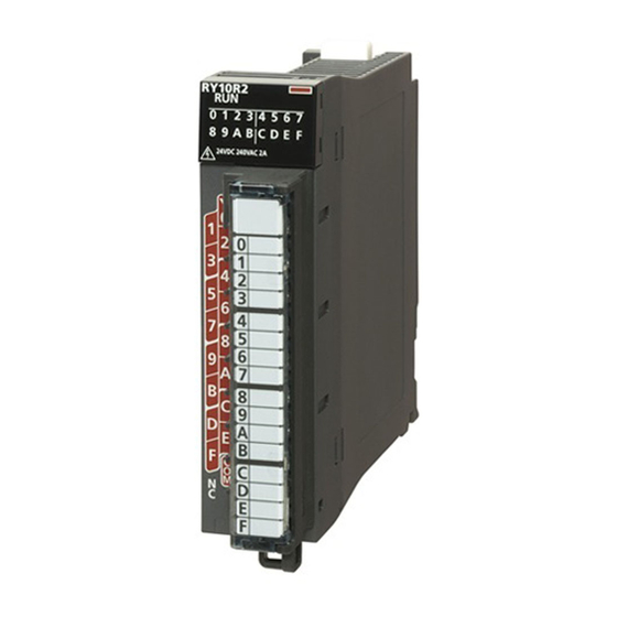
Page 18: Chapter 1 Part Names
PART NAMES This chapter describes the part names of the D/A converter module. Name Description RUN LED Indicates the operating status of the module. On: Normal operation Flashing (1s cycles): In offset/gain setting mode Flashing (400ms cycles): Selected as a module for the online module change Off: 5V power supply interrupted, watchdog timer error occurred, or module replacement allowed in the process of the online module change ERR LED... - Page 19 MEMO 1 PART NAMES...
-
Page 20: Chapter 2 Specifications
SPECIFICATIONS This chapter describes the performance specifications. Performance Specifications This section describes the performance specifications of the D/A converter module. Item Specifications Number of analog output channels 4 channels Digital input 16-bit signed binary value (-32768 to 32767) Analog output voltage -10 to10VDC (external load resistance value 1k... - Page 21 *1 For details on the I/O conversion characteristics, refer to the following. Page 52 I/O Conversion Characteristics *2 Maximum resolution in the user range setting. *3 Except for the conditions under noise influence. *4 The time required by the analog output signal from starting the output change to when the change is 90% complete. *5 A count more than 10000 times causes Number of writes to offset/gain settings reach limit error (error code: 1080H).
-
Page 22: Chapter 3 Function List
FUNCTION LIST The following shows the function list of the D/A converter module. For details on the functions, refer to the following. MELSEC iQ-R High Speed Digital-Analog Converter Module User's Manual (Application) Item Description Range switching function Allows switching the output range of an analog output for each channel. Switching the range makes it possible to change the I/O conversion characteristics. - Page 23 Availability in each operation mode The functions that can be used depend on the operation mode of the D/A converter module. The following table lists the availability of each function in each operation mode. : Available, : Not available Item Operation mode High speed Normal...
-
Page 24: Chapter 4 Procedures Before Operation
PROCEDURES BEFORE OPERATION This chapter describes the procedures before operation. Mounting a module Mount the D/A converter module in any desired configuration. Wiring Perform wiring of external devices to the D/A converter module. Page 27 External Wiring Adding a module Add the D/A converter module to a module configuration by using the engineering tool. - Page 25 MEMO 4 PROCEDURES BEFORE OPERATION...
-
Page 26: Chapter 5 System Configuration
SYSTEM CONFIGURATION For system configurations using the MELSEC iQ-R series modules, CPU modules that can be used with the D/A converter module, and the number of mountable modules, refer to the following. MELSEC iQ-R Module Configuration Manual 5 SYSTEM CONFIGURATION... - Page 27 MEMO 5 SYSTEM CONFIGURATION...
-
Page 28: Chapter 6 Wiring
WIRING This chapter describes the wiring of the D/A converter module. Terminal Block Precautions Tighten the module fixing screws and others within the specified torque range. Screw type Tightening torque range Module fixing screw (M3) 0.37 to 0.48Nm Terminal screw (M3) 0.42 to 0.58Nm Terminal block mounting screw (M3.5) 0.66 to 0.89Nm... -
Page 29: External Wiring
External Wiring Wiring to the terminal block The following figures show wiring to the terminal block. • For the voltage output +24V • For the current output +24V 6 WIRING 6.2 External Wiring... - Page 30 External wiring example The following figure shows the example of external wiring. Motor drive module or others For voltage output 1kΩ or more/ 500Ω or conversion more Motor drive module or others For current output 50Ω conversion 600Ω +24V 24VDC Filter *1 For the wire, use the 2-core twisted cable.
-
Page 31: Chapter 7 Operation Examples
OPERATION EXAMPLES This chapter describes the programming procedure and the basic program of the D/A converter module. Programming Procedure Take the following steps to create a program for executing the D/A conversion. Programs for normal output mode and wave output mode are described. For normal output mode Set module parameters. -
Page 32: Program Example (For Normal Output Mode)
Program Example (for Normal Output Mode) This section describes a program example when operating the D/A converter module in the normal output mode. System configuration The following figure is an example of the system configuration. (1) Power supply module (R61P) (2) CPU module (R04CPU) (3) D/A converter module (R60DAH4) (4) Input module (RX10) - Page 33 Operating procedure Set the window as follows to create the project. [Project] [New] Click the [Setting Change] button and set the module to use the module label. Click the [OK] button in the following window to add the module label of the CPU module. Add the D/A converter module with the window set as follows.
- Page 34 Set the window as follows to add the module label of the D/A converter module. Set "Basic setting" of "Module Parameter" of the D/A converter module as shown below. [Navigation window] [Parameter] [Module Information] [R60DAH4] [Module Parameter] [Basic setting] Set "Application setting"...
- Page 35 Label settings GX Works3 provides functions that support the creation of a program. The following table lists the module labels and global labels used for the program examples in this section. There is no need to change the settings of the module labels. For details on the global labels, refer to the following. ...
- Page 36 Program examples ■Program example 1 This program is an example in which the digital values for D/A conversion of CH1 to 4 are set in the D/A converter module, then the analog output is enabled to start D/A conversion. (0) Sets CH1 Digital value to CH4 Digital value. (82)Enables the outputs of CH1 to 4.
- Page 37 ■Program example 3 This program is an example to display the latest error code when a disconnection is detected or an error is generated in CH4 of the D/A converter module. Subsequently, the program clears Disconnection detection flag, Error flag, and the stored error code.
-
Page 38: Program Example (For Wave Output Mode)
Program Example (for Wave Output Mode) This section describes the program examples when operating the D/A converter module in the wave output mode. System configuration The following figure is an example of the system configuration. (1) Power supply module (R61P) (2) CPU module (R120CPU) (3) D/A converter module (R60DAH4) (4) Input module (RX10) - Page 39 Parameter settings Perform the initial settings in the module parameters and wave output data creation of the engineering tool. The auto refresh setting does not need to be changed here. ■Module parameter Set the module parameters as follows. Function Setting item Range switching function Output range setting -10 to 10V...
- Page 40 Add the D/A converter module with the window set as follows. [Navigation window] [Parameter] [Module Information] Right-click [Add New Module] Set the window as follows to add the module label of the D/A converter module. Set "Basic setting" of "Module Parameter" of the D/A converter module as shown below. [Navigation window] ...
- Page 41 Set "Application setting" of "Module Parameter" of the D/A converter module as shown below. [Navigation window] [Parameter] [Module Information] [R60DAH4] [Module Parameter] [Application setting] Write the set parameters to the CPU module on the master station. Then, reset the CPU module or power off and on the system.
- Page 42 ■Initial settings of the wave output function Create the wave pattern and parameters of wave output function in the wave output data creation tool. For details on the creation method, refer to the following. MELSEC iQ-R High Speed Digital-Analog Converter Module User's Manual (Application) Configure the file register settings of the CPU parameter as follows to enable usage of the file register.
- Page 43 In "Wave output data setting", set as follows. Click the [Write to Device Memory] button, and write the wave output data in the device memory. 7 OPERATION EXAMPLES 7.3 Program Example (for Wave Output Mode)
- Page 44 Label settings GX Works3 provides functions that support the creation of a program. The following table lists the module labels and global labels used for the program examples in this section. There is no need to change the settings of the module labels. For details on the global labels, refer to the following. ...
- Page 45 Program examples ■Wave output data read processing program example Set CH1 D/A conversion enable/disable setting to D/A conversion enable. Moreover, read the data from the file register (ZR) in which the wave pattern and parameter settings of wave output function are stored and register it in the buffer memory of the D/A converter module.
- Page 46 ■Wave output parameter setting processing program example This example shows the program to be used when part of the parameter settings of the wave output function read from the file register (ZR) and CSV file need to be changed. If there is no need to change the settings, this program is not required. After the change, enable the settings using the operating condition setting request program.
- Page 47 ■Operating condition setting request processing program example When newly registering wave output parameters or changing the setting values, enable the settings using this program. (607)Turns on the operating condition setting request function block start flag (M20). (631)Carries out operating condition setting request processing. (657)Turns off the operating condition setting request function block start flag (M20).
- Page 48 ■Wave output start processing program example This example shows a program for starting the CH1 wave output. (659)Turns on 'CH1 Output enable/disable flag' (Y1). (682)Turns on the wave data output start/stop request (X18) and sets the wave output start/stop request (D30) to the wave output start request (1). (686)When stopping the wave output, turns off the wave data output start/stop request (X18) and sets the wave output start/stop request (D30) to the wave output stop request (0).
-
Page 49: Chapter 8 Offset/Gain Setting
OFFSET/GAIN SETTING Using the user range setting requires setting the offset and gain values. Access the "Offset/Gain Setting" window in the engineering tool to set the offset and gain values. Setting procedure The procedure for the offset/gain setting of the D/A converter module is as follows. The offset/gain setting is disabled in the high-speed output mode, the wave output mode, and the inter-module synchronization mode. - Page 50 Click the [Yes] button. Specify the channel where offset and gain values are to be set and specify the user range setting. 8 OFFSET/GAIN SETTING...
- Page 51 Specify whether to configure the offset setting or gain setting with the radio button. (The steps from step 6 assume that the offset setting has been specified.) 8 OFFSET/GAIN SETTING...
- Page 52 The adjustment amount of the offset value or gain value has to be selected from "1", "100", "500", "1000", "2000", and "3000" first; however, further fine adjustments are also possible by entering a desired value (1 to 3000). 8 OFFSET/GAIN SETTING...
- Page 53 Click the [+(+)] button or [-(-)] button to make fine adjustments to the selected adjustment value to obtain the analog output voltage value or analog output current value. The "Offset Status" of the specified channel is changed to "Changed". To configure the gain setting, repeat the steps from step 5. After the setting is completed, click the [Close] button.
-
Page 54: Appendices
APPENDICES Appendix 1 I/O Conversion Characteristics An I/O conversion characteristic of D/A conversion is expressed by the slope of the straight line connecting the offset value and the gain value at the time when a digital value written from the CPU module is converted to an analog output value (voltage or current). - Page 55 Voltage output characteristic The following shows the list of the analog output ranges and the graph of each voltage output characteristic, at the voltage output. digit -32768 -32000 -768 32000 32767 digit: Digital value V: Analog output voltage (V) (a): Practical analog output range Analog output range setting Offset value Gain value...
- Page 56 Current output characteristic The following shows the list of the analog output ranges and the graph of each current output characteristic, at the current output. digit -768 32000 32767 digit: Digital value I: Analog output current (mA) (a): Practical analog output range Analog output range setting Offset value Gain value...
-
Page 57: Appendix 2 Accuracy
Appendix 2 Accuracy Accuracy of D/A conversion is determined by the accuracy of the maximum value of analog output value. An output characteristic change through changes of the offset/gain setting or the output range does not sacrifice the accuracy, which is maintained within the described range of the performance specifications. The following graph shows the fluctuation range of accuracy when the range of -10 to 10V is selected. -
Page 58: Appendix 3 Output Response Time
Appendix 3 Output Response Time The output response time is the time required by the analog output signal from starting the output change to when the change is 90% complete. The time is extended or reduced depending on the variation of analog output. Note that the output response time becomes longer (voltage output: 20s, current output: 10s) in the system with sudden output changes. -
Page 59: Appendix 4 External Dimensions
Appendix 4 External Dimensions The following figure shows the external dimensions of the D/A converter module. 27.8 (unit: mm) APPX Appendix 4 External Dimensions... -
Page 60: Index
INDEX ....55 Accuracy of D/A conversion ......16 ALM LED . - Page 61 MEMO...
-
Page 62: Revisions
Japanese manual number: SH-081654-B This manual confers no industrial property rights or any rights of any other kind, nor does it confer any patent licenses. Mitsubishi Electric Corporation cannot be held responsible for any problems involving industrial property rights which may occur as a result of using the contents noted in this manual. -
Page 63: Warranty
WARRANTY Please confirm the following product warranty details before using this product. 1. Gratis Warranty Term and Gratis Warranty Range If any faults or defects (hereinafter "Failure") found to be the responsibility of Mitsubishi occurs during use of the product within the gratis warranty term, the product shall be repaired at no cost via the sales representative or Mitsubishi Service Company. -
Page 64: Trademarks
TRADEMARKS The company names, system names and product names mentioned in this manual are either registered trademarks or trademarks of their respective companies. In some cases, trademark symbols such as ' ' or ' ' are not specified in this manual. SH(NA)-081655ENG-B... - Page 66 SH(NA)-081655ENG-B(2005)MEE MODEL: R60DAH4-U-IN-E MODEL CODE: 13JX57 HEAD OFFICE : TOKYO BUILDING, 2-7-3 MARUNOUCHI, CHIYODA-KU, TOKYO 100-8310, JAPAN NAGOYA WORKS : 1-14 , YADA-MINAMI 5-CHOME , HIGASHI-KU, NAGOYA , JAPAN When exported from Japan, this manual does not require application to the Ministry of Economy, Trade and Industry for service transaction permission.