
Related Manuals for Airflow Duplexvent DV65 Entro-V


Summary of Contents for Airflow Duplexvent DV65 Entro-V
- Page 1 80000993 – Issue 1 08/20 Duplexvent DV65/DV82/DV130 Entro-V Part No: 90001243/90001244/90001245 RESIDENTIAL HEAT RECOVERY UNITS User, maintenance and installation manual...
-
Page 2: Table Of Contents
10.7. Basic controller Functions ........................... 14 11. MAINTENANCE INSTRUCTIONS ........................... 15 11.1 Heat Exchanger Maintenance ........................15 11.2 Filter Maintenance ............................16 11.3 Fan Maintenance ............................. 16 12. OPERATING INSTRUCTIONS ..........................17 13. CONTROL FEATURES ............................. 18 14. TROUBLESHOOTING ............................. 19 www.airflow.com... -
Page 3: Warnings & Safety Information
Dirty filters should be placed in a sealed container and be destroyed in compliance with local solid waste procedures. Care should be taken to not damage the fans when cleaning. It is recommended that a soft brush or vacuum cleaner to be used. www.airflow.com... -
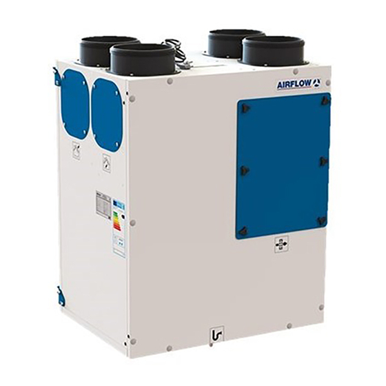
Page 4: Main Components
3. MAIN COMPONENTS The unit is designed to recovering thermal energy from the exhausted air in a ventilation system. The recovered energy is directly transferred to the incoming fresh air supply, this can reduce load on the property heating systems. www.airflow.com... -
Page 5: Technical Data
Galvanised steel. Powder Galvanised steel. Powder Casing paint. (20mm insulation) paint. (20mm insulation) paint. (20mm insulation) Wall, Floor Wall, Floor Wall, Floor Mounting Orientation of unit Right or Left-handed Right or Left-handed Right or Left-handed Part no. 90001243 90001244 90001245 www.airflow.com... -
Page 6: Unit Dimensions
MODELS DV65 Entro-V DV82 Entro-V DV130 Entro-V Service Space: All measurement values are mm. A clear space must be provided in front of the unit for service. E is the spigot diameter. D is the minimum service space required. www.airflow.com... -
Page 7: Unit Labels
USER AND MAİNTENANCE MANUAL 7. UNIT LABELS Please see product labels and their individual definitions: DV65 Entro-V Return Air Supply Air Product Label Exhaust Air DV65 Entro-V Outside Air Drainage Filter Electric Panel Energy Label www.airflow.com... -
Page 8: Installation
M8 flush steel dowel is fixed to wall. The M8 imbus bolt is compressed so that it passes through the hanger. Hang the device onto the bracket. Must be horizontal balanced when wall and floor mounting. www.airflow.com... -
Page 9: Discharge Condensate Installation
Suitable water trap measures should be taken (see below). Pipe runs should slope away from the unit enabling condensation to drain away. *Apply a fixing adhesive to the drain connection part for sealing. *Install the condensation connection part in the allocated drainage space. *Tighten it well by using a spaner. www.airflow.com... -
Page 10: Optional Spigot Installation
3. Install spigots to the relevant position on the side of the unit and secure with the 4 retaining screws. 4. Install the blanking plates to the exit hole on the upper side and secure with the 4 retaining screws. www.airflow.com... -
Page 11: Control Options
3 sec to reset filter time on the basic controller. Note: Default run time set value is changeable when using the digital controller which is an optional controller. www.airflow.com... -
Page 12: By-Pass Function (Optional)
3 seconds. When 1. “Boost” function is activated by pressing activated the unit runs at boost speed (maximum speed) for 15 minutes, after which the unit will return to its commissioned everyday running rate fan speed. www.airflow.com... -
Page 13: Warnings
“boost” speed. When the input is passive again (turn off the switch), the unit runs at the speed value it was set before the switch was turned on. See input output connection below. For light switch connection, see relay contact connection below. www.airflow.com... -
Page 14: Basic Controller Functions
Duplexvent Entro-V Line USER AND MAİNTENANCE MANUAL 10.7. Basic Controller Functions www.airflow.com... -
Page 15: Maintenance Instructions
Isolate unit before carrying out any work. Work to be carried out only by a competent person. Do not use corrosive, or aggressive cleaning agents. Dust can best be removed from air inlet and outlet areas by using a normal vacuum cleaner. www.airflow.com... -
Page 16: Filter Maintenance
Install the filter into the chamber with the same instructions. 11.3 Fan Maintenance Only by competent personnel Isolate the electric supply to unit Remove the panels of the unit Unplug the fan cables and remove the fans Clean fans with soft brush or vacuum www.airflow.com... -
Page 17: Operating Instructions
This unit must be correctly earthed. Do not connect any accessories or ancillaries, such as the controller or any additional sensors unless the unit is down powered and isolated from mains electricity supply By default, the fans are set-up at the following speeds: www.airflow.com... -
Page 18: Control Features
Fan Speed Control Constant air flow is available with pressure sensors. Optional Fan Speed Control Airflow control based on the air quality sensor is available. Optional Free cooling is available by controlling the indoor and outdoor Bypass Damper Function Standard air conditions. -
Page 19: Troubleshooting
The condensate pipe is not ✓Push the pipe deeper into the completely in the trap. trap. The condensate pipe or condensate ✓Check the condensate drain and trap is blocked of frozen. clean it, if necessary www.airflow.com... - Page 20 Duplexvent Entro-V Line USER AND MAİNTENANCE MANUAL WIRING DIAGRAM www.airflow.com...
- Page 21 E: infor@airflow.com Airflow Developments Limited Aidelle House, Lancaster Road T: 44 (0) 1494 525252 W: airflow.com Cressex Business Park, High Wycombe Buckinghamshire, HP12 3QP, U.K ©Copyright 2016. Airflow Developments Ltd...