Huawei UPS5000-H Series User Manual
100 kva power module
Hide thumbs
Also See for UPS5000-H Series:
- User manual (395 pages) ,
- Quick manual (8 pages) ,
- Quick manual (3 pages)

Related Manuals for Huawei UPS5000-H Series


Summary of Contents for Huawei UPS5000-H Series
- Page 1 UPS5000-H-(400 kVA-600 kVA) User Manual (100 kVA Power Module) Issue Date 2020-11-30 HUAWEI TECHNOLOGIES CO., LTD.
- Page 2 Notice The purchased products, services and features are stipulated by the contract made between Huawei and the customer. All or part of the products, services and features described in this document may not be within the purchase scope or the usage scope. Unless otherwise specified in the contract, all statements, information, and recommendations in this document are provided "AS IS"...
-
Page 3: About This Document
Indicates a hazard with a medium level of risk which, if not avoided, could result in death or serious injury. Indicates a hazard with a low level of risk which, if not avoided, could result in minor or moderate injury. Issue 01 (2020-11-30) Copyright © Huawei Technologies Co., Ltd. - Page 4 Change History Changes between document issues are cumulative. The latest document issue contains all updates made in previous issues. Issue 01 (2020-11-30) This issue is the first release. Issue 01 (2020-11-30) Copyright © Huawei Technologies Co., Ltd.
-
Page 5: Table Of Contents
4 Component Description....................... 26 4.1 Power Module..................................26 4.2 Bypass Module..................................27 4.3 Control Module..................................29 4.3.1 Overview....................................29 4.3.2 ECM......................................29 4.3.3 Dry Contact Card................................31 4.3.4 Monitoring Interface Card.............................. 34 Issue 01 (2020-11-30) Copyright © Huawei Technologies Co., Ltd. - Page 6 7.5 Setting ECO Mode................................76 7.6 Testing Batteries..................................77 7.6.1 Lead-Acid Battery Test..............................77 7.6.1.1 Performing a Forced Equalized Charging Test..................... 77 7.6.1.2 Performing a Shallow Discharge Test........................78 7.6.1.3 Performing a Capacity Test............................79 Issue 01 (2020-11-30) Copyright © Huawei Technologies Co., Ltd.
- Page 7 8.2.1 Precautions for Battery Maintenance......................... 91 8.2.2 Monthly Maintenance..............................91 8.2.3 Quarterly Maintenance..............................92 8.2.4 Annual Maintenance................................ 94 9 Troubleshooting........................95 10 Technical Specifications.....................98 A (Optional) TN-C System Application................104 B Lifting Trolley........................105 C Acronyms and Abbreviations................... 107 Issue 01 (2020-11-30) Copyright © Huawei Technologies Co., Ltd.
-
Page 8: Safety Information
The "NOTICE", "CAUTION", "WARNING", and "DANGER" statements in this document do not cover all the safety instructions. They are only supplements to the safety instructions. Huawei will not be liable for any consequence caused by the violation of general safety requirements or design, production, and usage safety standards. - Page 9 ● Keep irrelevant people away from the equipment. Only operators are allowed to access the equipment. ● Use insulated tools or tools with insulated handles, as shown in the following figure. Issue 01 (2020-11-30) Copyright © Huawei Technologies Co., Ltd.
- Page 10 Do not change the structure or installation sequence of equipment without permission. ● Do not touch a running fan with your fingers, components, screws, tools, or boards before the fan is powered off or stops running. Issue 01 (2020-11-30) Copyright © Huawei Technologies Co., Ltd.
-
Page 11: Personnel Requirements
Do not power on the equipment before it is installed or confirmed by professionals. 1.2 Personnel Requirements ● Personnel who plan to install or maintain Huawei equipment must receive thorough training, understand all necessary safety precautions, and be able to correctly perform all operations. ●... - Page 12 0°C. Handle cables with caution, especially at a low temperature. – Cables stored at subzero temperatures must be stored at room temperature for at least 24 hours before they are laid out. Issue 01 (2020-11-30) Copyright © Huawei Technologies Co., Ltd.
-
Page 13: Installation Environment Requirements
Install the equipment in an area far away from liquids. Do not install it under areas prone to condensation, such as under water pipes and air exhaust vents, or areas prone to water leakage, such as air conditioner vents, ventilation Issue 01 (2020-11-30) Copyright © Huawei Technologies Co., Ltd. - Page 14 Any violations must be promptly pointed out by the site manager or safety supervisor and the involved personnel should be prompted for correction. Personnel who fail to stop violations will be forbidden from working. Issue 01 (2020-11-30) Copyright © Huawei Technologies Co., Ltd.
-
Page 15: Mechanical Safety
Ensure that the wider end of the ladder is at the bottom, or protective measures have been taken at the bottom to prevent the ladder from sliding. Issue 01 (2020-11-30) Copyright © Huawei Technologies Co., Ltd. - Page 16 D ANGER When removing a heavy or unstable component from a cabinet, be aware of unstable or heavy objects on the cabinet. ● Be cautious to avoid injury when moving heavy objects. Issue 01 (2020-11-30) Copyright © Huawei Technologies Co., Ltd.
-
Page 17: Device Running Safety
The UPS operating environment must meet the requirements for the climate indicator, mechanically active substance indicator, and chemically active substance indicator in ETSI EN 300 019-1 class 3.6. Issue 01 (2020-11-30) Copyright © Huawei Technologies Co., Ltd. - Page 18 UPS is connected to a backfeed protection card. Disconnect the backfeed protection card from the UPS before operating the UPS. Do not use the UPS in the following places: Issue 01 (2020-11-30) Copyright © Huawei Technologies Co., Ltd.
-
Page 19: Battery Safety
● Dispose of waste batteries in accordance with local laws and regulations. Do not dispose of batteries as household waste. If a battery is disposed of improperly, it may explode. Issue 01 (2020-11-30) Copyright © Huawei Technologies Co., Ltd. - Page 20 NO TICE To ensure battery safety and battery management accuracy, use batteries provided with the UPS by Huawei. Huawei is not responsible for any battery faults caused by batteries not provided by Huawei. Battery Installation Before installing batteries, observe the following safety precautions: ●...
- Page 21 Use batteries within the allowed temperature range; otherwise, the battery performance and safety will be compromised. ● Do not throw a lithium battery in fire. ● When maintenance is complete, return the waste lithium battery to the maintenance office. Issue 01 (2020-11-30) Copyright © Huawei Technologies Co., Ltd.
-
Page 22: Others
UPS output voltage level or frequency. Doing so may affect the power supply to equipment. ● Exercise caution when setting battery parameters. Incorrect settings will affect the power supply and battery lifespan. Issue 01 (2020-11-30) Copyright © Huawei Technologies Co., Ltd. -
Page 23: Product Overview
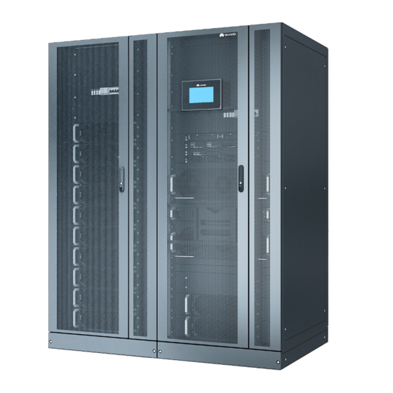
2 Product Overview Product Overview 2.1 Positioning The UPS5000-H is a high-end modular UPS launched by Huawei. It adopts online double conversion and modular redundancy design for components. Based on the digital signal processing (DSP) technology, the UPS5000-H features high efficiency and power density. -
Page 24: Application Scenario
Parallel system Supplies power to large-sized A maximum of four equipment rooms or important UPSs can be connected loads. It features high reliability and in parallel. strong transient overload resistance capability. Issue 01 (2020-11-30) Copyright © Huawei Technologies Co., Ltd. - Page 25 In addition to advantages of common parallel systems, the multi-bus system is free from bottleneck failures, but its configuration is complex. Figure 2-1 Typical application scenario of a single UPS Issue 01 (2020-11-30) Copyright © Huawei Technologies Co., Ltd.
- Page 26 UPS5000-H-(400 kVA-600 kVA) User Manual (100 kVA Power Module) 2 Product Overview Figure 2-2 Typical application scenario of a 1+1 parallel system Issue 01 (2020-11-30) Copyright © Huawei Technologies Co., Ltd.
-
Page 27: Conceptual Diagram
The UPS uses the DSP technology for intelligent control. The power module consists of a rectifier, inverter, and DC/DC converter. The UPS converts inputs into pure high-quality sine wave outputs by using the high-frequency switching technology. Issue 01 (2020-11-30) Copyright © Huawei Technologies Co., Ltd. -
Page 28: Working Modes
UPS automatically transfers to bypass mode. At the same time, the rectifier is started and charges batteries over a charger. In bypass mode, loads are powered by the bypass Issue 01 (2020-11-30) Copyright © Huawei Technologies Co., Ltd. -
Page 29: Battery Mode
ECO power supply conditions are met, the UPS works in bypass mode and the inverter is in standby state. When the bypass source voltage is outside the ECO voltage range, the UPS transfers from bypass mode to inverter mode. In bypass Issue 01 (2020-11-30) Copyright © Huawei Technologies Co., Ltd. -
Page 30: Source-Share Mode
UPS transfers to source-share mode. In this case, the power module obtains energy from both the mains and batteries, and the energy is converted into AC outputs by the inverter. Figure 2-9 Conceptual diagram in source-share mode Issue 01 (2020-11-30) Copyright © Huawei Technologies Co., Ltd. -
Page 31: Product Introduction
600K: The output capacity is 600 kVA. 500K: The output capacity is 500 kVA. 400K: The output capacity is 400 kVA. Switch N: no switch configuration Cabling T: Cables can only be routed in from the top. Issue 01 (2020-11-30) Copyright © Huawei Technologies Co., Ltd. -
Page 32: Cabinet Description
600 kVA UPS as an example. Four power modules are configured for a 400 kVA UPS. Five power modules are configured for a 500 kVA UPS. Six power modules are configured for a 600 kVA UPS. Issue 01 (2020-11-30) Copyright © Huawei Technologies Co., Ltd. -
Page 33: Component Description
(blinking at 0.5 Hz, on for 1s and off for 1s). intervals ● The inverter is not started (blinking at 0.2 Hz, on for 2.5s and off for 2.5s). Issue 01 (2020-11-30) Copyright © Huawei Technologies Co., Ltd. -
Page 34: Bypass Module
The power module overload times out. ● Both active and standby energy control modules (ECMs) in the system are abnormal. ● The system runs abnormally. ● The UPS is transferred to bypass mode manually. Issue 01 (2020-11-30) Copyright © Huawei Technologies Co., Ltd. - Page 35 Fault Steady on A critical alarm is generated for the indicator bypass. There is no critical alarm for the bypass, or the software is being upgraded. Issue 01 (2020-11-30) Copyright © Huawei Technologies Co., Ltd.
-
Page 36: Control Module
The ECM ensures equalized output currents between modules so that load power is equally shared. Issue 01 (2020-11-30) Copyright © Huawei Technologies Co., Ltd. - Page 37 This ECM is the standby ECM and it is ready. This ECM is not ready or the software of this ECM is being upgraded. Blinking at 4 Hz The ECM software is being upgraded or not configured. Issue 01 (2020-11-30) Copyright © Huawei Technologies Co., Ltd.
-
Page 38: Dry Contact Card
The dry contact card allows the UPS to detect and manage the switch status of the battery system (including the external battery switch) and implement remote emergency power off (EPO). The dry contact card is 0.5 U high and hot- swappable. Issue 01 (2020-11-30) Copyright © Huawei Technologies Co., Ltd. - Page 39 (DG) mode mode ● Open: non-DG Port for signal ground mode BCB_OL Port for monitoring the ● Grounded: BCB Grounde battery circuit breaker (BCB) box connected ● Disconnected: BCB box not connected Issue 01 (2020-11-30) Copyright © Huawei Technologies Co., Ltd.
- Page 40 Port for signal ground is ON. STATUS_0V ● Open: The bypass input circuit breaker is OFF. Port for monitoring the ● Closed: The Closed input AC SPD input AC SPD is normal. Issue 01 (2020-11-30) Copyright © Huawei Technologies Co., Ltd.
-
Page 41: Monitoring Interface Card
UPS. Figure 4-7 Monitoring interface card NO TE DO_1 to DO_4 meet the maximum voltage and current requirements of 30 V DC/1 A or 60 V DC/0.5 A. Issue 01 (2020-11-30) Copyright © Huawei Technologies Co., Ltd. - Page 42 ● Signal cables must be double-insulated twisted cables. If the cable length is within 25– 50 m, the cross-sectional area must be 0.5–1.5 mm ● RS485 cables and FE cables must be shielded cables. Figure 4-8 Figure 4-9 are recommended wiring methods for DO ports. Issue 01 (2020-11-30) Copyright © Huawei Technologies Co., Ltd.
- Page 43 User Manual (100 kVA Power Module) 4 Component Description Figure 4-8 Wiring method 1 Figure 4-9 Wiring method 2 Figure 4-10 COM1 port pins Table 4-9 Pin definitions for the COM1 port Description RS485– RS485+ 12V_PORT Issue 01 (2020-11-30) Copyright © Huawei Technologies Co., Ltd.
- Page 44 User Manual (100 kVA Power Module) 4 Component Description Figure 4-11 COM2 port pins Table 4-10 Pin definitions for the COM2 port Description RS485+ RS485– RS485+ RS485– CANH0 CANL0 Figure 4-12 RS485 port pins Issue 01 (2020-11-30) Copyright © Huawei Technologies Co., Ltd.
-
Page 45: Mdu
For details, see the Dimensions (H x W x D): 175 mm x 264 mm x 40 mm Figure 4-13 Appearance (1) Status indicator (2) LCD touchscreen Issue 01 (2020-11-30) Copyright © Huawei Technologies Co., Ltd. - Page 46 Figure 4-14 MDU ports Table 4-13 MDU port description Port Name Description MUS05A Connects to the MDU and monitoring interface card. (DB26) Network port Reserved RS485_1 Reserved FE_1 Reserved FE_2 Reserved Issue 01 (2020-11-30) Copyright © Huawei Technologies Co., Ltd.
- Page 47 View or obtain UPS running information during inspection. NOTE Only Huawei service engineers or authorized service engineers are allowed to use the WiFi module. To ensure security, remove the WiFi module immediately after use.
-
Page 48: Optional Components
Backfeed Detects mains and bypass backfeed and protection card provides protection. ECM extended Installed when the UPS is equipped with subrack a backfeed protection card and dry contact extended card. Issue 01 (2020-11-30) Copyright © Huawei Technologies Co., Ltd. -
Page 49: Dry Contact Extended Card
The ECM extended subrack, surge protection box subrack, and intelligent detection card do not support onsite installation. If you require the optional components, inform Huawei when you purchase the UPS so that Huawei can install them before delivery. 5.2 Dry Contact Extended Card... -
Page 50: Backfeed Protection Card
Figure 5-3 Surge protection box (1) Working status indicators 5.5 BCB Box The BCB box controls the connection between battery strings and the UPS, and supports overload protection, short circuit protection, and remote trip control. Issue 01 (2020-11-30) Copyright © Huawei Technologies Co., Ltd. -
Page 51: Bbb Box
Breaking capacity (kA) IP rating 5.6 BBB Box The BBB box connects the UPS and the battery system. It converges the energy of multiple battery strings, supplying DC power to the UPS. Issue 01 (2020-11-30) Copyright © Huawei Technologies Co., Ltd. -
Page 52: Ambient T/H Sensor
32 to 44. A DIP switch has six binary toggle switches. The bit on the leftmost is the most significant bit, and the bit on the rightmost is the least significant bit. Bit 1 indicates ON, and bit 0 indicates OFF. Issue 01 (2020-11-30) Copyright © Huawei Technologies Co., Ltd. - Page 53 Figure 5-7 DIP switch on the ambient T/H sensor (1) DIP switch Table 5-3 DIP switch address mapping When the ambient T/H sensor is used as a battery temperature sensor, the DIP switch address ranges from 16 to 28. Issue 01 (2020-11-30) Copyright © Huawei Technologies Co., Ltd.
- Page 54 UPS5000-H-(400 kVA-600 kVA) User Manual (100 kVA Power Module) 5 Optional Components Table 5-4 DIP switch address mapping (battery temperature sensor) Issue 01 (2020-11-30) Copyright © Huawei Technologies Co., Ltd.
-
Page 55: Installation
20°C reduce the battery backup time. ● Ensure that the floor or installation support can bear the weight of the UPS, batteries, and battery racks. Issue 01 (2020-11-30) Copyright © Huawei Technologies Co., Ltd. -
Page 56: Installation Clearances
● The following table lists only the common tools for installation and cable connection. For more dedicated tools required, see the document for each component. Prepare tools based on site requirements. Issue 01 (2020-11-30) Copyright © Huawei Technologies Co., Ltd. - Page 57 Hand-held electric drill Hole saw Heat gun Φ16 drill bit) Diagonal pliers Crimping tool Wire strippers Electro-hydraulic pliers Clamp meter Multimeter Cable tie Level Insulation tape Cotton cloth Labels Electrician's knife Issue 01 (2020-11-30) Copyright © Huawei Technologies Co., Ltd.
- Page 58 Tools and Instruments ESD gloves Protective gloves Insulation gloves Insulated protective shoes Torque screwdriver Cable cutter Brush Flat-head screwdriver (2–5 mm) Phillips screwdriver Insulated torque wrench Heat-shrink tubing Insulated adjustable wrench (M3/M4/M5/M6/M8) (M6/M8/M12/M16) Issue 01 (2020-11-30) Copyright © Huawei Technologies Co., Ltd.
-
Page 59: Power Cable Selection
400 kVA 500 kVA 600 kVA Mains input Mains input current 1115 Recommende 2 x (4 x 3 x (4 x 4 x (4 x d cross- 240) 240) 185) sectional area Issue 01 (2020-11-30) Copyright © Huawei Technologies Co., Ltd. - Page 60 Battery Nominal battery 1028 1234 input discharge current (SmartLi) Maximum battery 1032 1290 1547 discharge current Recommended For details, see the IEC 60364-5-52 cross-sectional area specifications and SmartLi user manual. Issue 01 (2020-11-30) Copyright © Huawei Technologies Co., Ltd.
- Page 61 The 90°C flexible cables with copper conductors are used. – It is recommended that AC power cables be no longer than 30 meters and DC power cables be no longer than 50 meters. Issue 01 (2020-11-30) Copyright © Huawei Technologies Co., Ltd.
-
Page 62: Unpacking
● If multiple loads are connected, use recommended specifications for branch circuit breakers. ● The circuit breaker selection principle is to protect loads and cables, and the cascading principle is to achieve specific protection. 6.1.4 Unpacking Issue 01 (2020-11-30) Copyright © Huawei Technologies Co., Ltd. -
Page 63: Installing A Cabinet
Step 1 Use a pallet truck to transport the UPS cabinet to the specified place, unpack the cabinet, and remove the screws that secure the UPS to the wooden pallet. Figure 6-3 Unpacking ----End 6.2 Installing a Cabinet 6.2.1 Installation on the Floor Issue 01 (2020-11-30) Copyright © Huawei Technologies Co., Ltd. - Page 64 The unit is mm. Drill holes and install expansion sleeves. Secure the cabinet to the floor. Install anchor baffle plates. Figure 6-4 Installing a cabinet ----End Issue 01 (2020-11-30) Copyright © Huawei Technologies Co., Ltd.
-
Page 65: Installation On Channel Steel
6.2.2 Installation on Channel Steel Prerequisites NO TICE ● Huawei does not provide channel steel or expansion bolts for securing channel steel. Customers need to purchase them by themselves. ● Ensure that the surface of channel steel is level. Figure 6-5 Recommended channel steel dimensions (unit: mm) - Page 66 Choose an appropriate cabling route based on the actual situation. The figure is for reference only. Step 4 Connect the cable with a crimped terminal to the corresponding copper bar. Step 5 Clear sundries inside the cabinet. ----End Issue 01 (2020-11-30) Copyright © Huawei Technologies Co., Ltd.
-
Page 67: Installing Cabinet Cables
Step 1 Open the front door of the cabinet, remove the power distribution cover, and remove the top cover as required. Figure 6-7 Removing the covers Step 2 Install ground cables. Issue 01 (2020-11-30) Copyright © Huawei Technologies Co., Ltd. - Page 68 Cables of the same group, for example, mains input cables, must be routed through the same cable hole. ● One power source Figure 6-9 Installing cables (1) Wiring terminal (2) Spring washer (3) Bolt Issue 01 (2020-11-30) Copyright © Huawei Technologies Co., Ltd.
- Page 69 RS485 port on the monitoring interface card. NO TICE ● Do not bind signal cables and power cables together. ● RS485 cables and FE cables must be shielded cables. Issue 01 (2020-11-30) Copyright © Huawei Technologies Co., Ltd.
-
Page 70: Connecting Cables Between The Ups And The Smartli
COM port on the master SmartLi cabinet. NO TE ● The following figure uses the scenario with a BBB box configured as an example. ● The number and colors of cables are for reference only. Issue 01 (2020-11-30) Copyright © Huawei Technologies Co., Ltd. -
Page 71: Connecting A Remote Epo Switch
6.3.4 Connecting a Remote EPO Switch NO TICE ● Huawei does not provide the EPO switch or cable. Prepare them by yourself. The recommended cable is 22 AWG. ● Equip the EPO switch with a protective cover to prevent misoperations, and protect the cable with a protective tube. -
Page 72: Verifying The Installation
The UPS and its adjacent cabinets are neatly arranged and secured with connecting kits. Layout of the busway The busway and cables are routed properly as and cables required by the customer. Issue 01 (2020-11-30) Copyright © Huawei Technologies Co., Ltd. - Page 73 2. After verifying the installation, reinstall all the covers. 3. Do not remove the dustproof cover before power-on to prevent dust from entering the cabinets. Issue 01 (2020-11-30) Copyright © Huawei Technologies Co., Ltd.
-
Page 74: System Commissioning
● Before power-on, ensure that the devices have passed all check items in section "Verifying the Installation." ● Before power-on, ensure that all the UPS switches and upstream switches are OFF. Issue 01 (2020-11-30) Copyright © Huawei Technologies Co., Ltd. -
Page 75: Initial Startup
User Manual (100 kVA Power Module) 7 System Commissioning Procedure Step 1 Turn on the upstream bypass and mains input switches. After the UPS is powered on, initialization begins. The MDU displays the Huawei logo and an initialization progress bar. ----End 7.1.1 Initial Startup Procedure ●... - Page 76 The UPS may also be shut down earlier during discharging, which may cause data backup failures. If you cannot determine the capacity of a single battery, contact Huawei technical support. –...
- Page 77 Monitoring > UPS System > Running Parameter > System Settings on the WebUI and set EPO detection to Enable. Step 4 View the system running status diagram on the LCD to check that the UPS is working in bypass mode. ----End Issue 01 (2020-11-30) Copyright © Huawei Technologies Co., Ltd.
-
Page 78: Starting The Inverter
Step 5 To ensure system security, change the preset password after login. Step 6 On the WebUI, choose Monitoring > UPS System > Running Control, and click Inv. ON, and confirm the operation to start the inverter. Issue 01 (2020-11-30) Copyright © Huawei Technologies Co., Ltd. -
Page 79: Powering On Loads
A BCB box is installed. Procedure Step 1 Choose System Info > Settings > Dry Contact Set, set MUE05A connection to Enable, and set BCB connection [OL] and Battery breaker [STA] to Enable. Issue 01 (2020-11-30) Copyright © Huawei Technologies Co., Ltd. -
Page 80: Shutting Down And Powering Off The Ups
Choose Monitoring > UPS System > Running Control, and click Inv. OFF. If the inverter shuts down and the bypass is normal, the UPS transfers to bypass mode. The Bypass mode alarm is displayed on the LCD. Issue 01 (2020-11-30) Copyright © Huawei Technologies Co., Ltd. -
Page 81: Cold-Starting The Ups Using Batteries
If there are multiple battery strings, switch on the circuit breaker for each battery string and then the general circuit breaker between the battery strings and the UPS. Issue 01 (2020-11-30) Copyright © Huawei Technologies Co., Ltd. -
Page 82: Transferring To Bypass Mode Manually
1 Hz or is steady on, press and hold down the BATT START button on the UPS bypass control module for more than 2 seconds. The system automatically enters the battery cold start state. The MDU displays the Huawei logo and an initialization progress bar. -
Page 83: Setting Eco Mode
LCD. Step 2 Set the ECO voltage range. Figure 7-7 ECO specifications Step 3 (Optional) If you set ECO mode in bypass mode, manually start the UPS inverter. Issue 01 (2020-11-30) Copyright © Huawei Technologies Co., Ltd. -
Page 84: Testing Batteries
Step 1 On the home screen of the LCD, choose System Info > Maintenance > Battery Maint. Step 2 Tap Start on the right of Forced Equalized Charging to start a forced equalized charging test. Issue 01 (2020-11-30) Copyright © Huawei Technologies Co., Ltd. -
Page 85: Performing A Shallow Discharge Test
After setting is complete, the system will perform an automatic shallow discharge test based on the settings. ----End Manual Shallow Discharge Test Step 1 On the home screen of the LCD, choose System Info > Maintenance > Battery Maint. Issue 01 (2020-11-30) Copyright © Huawei Technologies Co., Ltd. -
Page 86: Performing A Capacity Test
● The mains, batteries, charger, and discharger are normal. No overload alarm is generated. Procedure Step 1 On the home screen of the LCD, choose System Info > Maintenance > Battery Maint. Issue 01 (2020-11-30) Copyright © Huawei Technologies Co., Ltd. -
Page 87: Lithium Battery Test
No generator is connected to the UPS. ● The mains, batteries, charger, and discharger are normal. No overload alarm is generated. ● The SmartLi generates no alarms related to lithium batteries. Issue 01 (2020-11-30) Copyright © Huawei Technologies Co., Ltd. -
Page 88: Performing A Capacity Test
● The battery discharge capacity reaches the specified value (10%–50%, 20% by default). ● The discharge voltage reaches the warning threshold (calculated in real time). ● The load rate fluctuation exceeds 10%. ● An alarm is generated. 7.6.2.2 Performing a Capacity Test Issue 01 (2020-11-30) Copyright © Huawei Technologies Co., Ltd. -
Page 89: Downloading The Test Data
The test is complete when the minimum cell voltage reaches 2.65 V. The test data is obtained from the capacity test. Save the test data obtained from the latest 36 tests. ----End 7.6.3 Downloading the Test Data Issue 01 (2020-11-30) Copyright © Huawei Technologies Co., Ltd. -
Page 90: Transferring To Maintenance Bypass Mode
LCD. Step 3 Turn on the maintenance bypass switch for external power distribution. Then, the Maint. breaker closed and Bypass mode alarms are displayed on the LCD. ----End Issue 01 (2020-11-30) Copyright © Huawei Technologies Co., Ltd. -
Page 91: Transferring From Maintenance Bypass Mode To Inverter Mode
4-pin terminal on the EPO port of the dry contact card. The UPS enters the emergency shutdown state. EPO and No power supplied alarms are displayed. Figure 7-16 EPO port ----End 7.10 Clearing the EPO State Issue 01 (2020-11-30) Copyright © Huawei Technologies Co., Ltd. -
Page 92: Exporting Data
The following data can be exported: ● Historical alarms ● Active alarms ● Performance data ● Operation logs ● E-label ● Fault information NO TE This procedure describes how to export historical alarms. Issue 01 (2020-11-30) Copyright © Huawei Technologies Co., Ltd. -
Page 93: Setting Hibernation Mode
Step 1 On the WebUI, choose Monitoring > UPS System > Running Parameter > System Settings, and set Paral sys hibernate to Enable. Step 2 Set Module cycle hiber period(d) to an integer ranging from 1 to 100. The default value is 30. Issue 01 (2020-11-30) Copyright © Huawei Technologies Co., Ltd. - Page 94 UPS5000-H-(400 kVA-600 kVA) User Manual (100 kVA Power Module) 7 System Commissioning Figure 7-18 System settings NO TE Click Submit after setting parameters on the WebUI. ----End Issue 01 (2020-11-30) Copyright © Huawei Technologies Co., Ltd.
-
Page 95: Routine Maintenance
Customers are not allowed to maintain components behind protective covers that can be removed only using tools. If the components are to be maintained, contact Huawei technical support. ● Only maintenance engineers can maintain power modules and bypass modules. -
Page 96: Monthly Maintenance
Wipe the cabinet surface using Remove the dust, especially a white paper and the paper from the air filter on the front does not turn black. door, or replace the air filter. Issue 01 (2020-11-30) Copyright © Huawei Technologies Co., Ltd. -
Page 97: Annual Maintenance
● Replace the circuit breaker through-current cables meet load breaker. capacity requirements. ● Replace the cable. The actual cable through-current capacity is greater than the circuit breaker specifications. 8.2 Lead-Acid Battery Maintenance Issue 01 (2020-11-30) Copyright © Huawei Technologies Co., Ltd. -
Page 98: Precautions For Battery Maintenance
Huawei technical support. 2. The battery terminals are intact. 3. Batteries are free from damage and cracks. 4. Batteries are free from acid leakage. 5. Batteries are not deformed or bulged. Issue 01 (2020-11-30) Copyright © Huawei Technologies Co., Ltd. -
Page 99: Quarterly Maintenance
2. Replace the battery the temperature displayed temperature sensor. on the MDU is less than 3°C. Issue 01 (2020-11-30) Copyright © Huawei Technologies Co., Ltd. - Page 100 UPS is backed up to verify locate the fault (for that the batteries can abnormal alarms, see discharge normally. the alarm list). 2. If the fault persists, contact Huawei technical support. Issue 01 (2020-11-30) Copyright © Huawei Technologies Co., Ltd.
-
Page 101: Annual Maintenance
(A torque wrench is used for checking the torque. After checking that the battery screws meet the requirements, mark the screws for later check.) Issue 01 (2020-11-30) Copyright © Huawei Technologies Co., Ltd. -
Page 102: Troubleshooting
EOD voltage and 11.3 V/cell. For details about how to rectify common faults, see Table 9-1. If any unmentioned faults occur, see the alarm list or contact Huawei technical support. Issue 01 (2020-11-30) Copyright © Huawei Technologies Co., Ltd. - Page 103 The buzzer buzzes, The bypass thyristor Replace the bypass bypass is and the fault is damaged. module. abnormal indicator is on. Issue 01 (2020-11-30) Copyright © Huawei Technologies Co., Ltd.
- Page 104 UPS5000 & SmartLi Alarm Reference . ● For details about the alarm list, see the ● For details about component replacement and maintenance involved in Troubleshooting and Alarm List, consult Huawei maintenance engineers. Issue 01 (2020-11-30) Copyright © Huawei Technologies Co., Ltd.
-
Page 105: Technical Specifications
0%–95% RH (non-condensing) Altitude 0–1000 m When the altitude is greater than 1000 m, the power is derated as described in IEC 62040-3. The upper limit of the altitude is 4000 m. Issue 01 (2020-11-30) Copyright © Huawei Technologies Co., Ltd. - Page 106 IEC 61000-4-5 Voltage dips and short IEC 61000-4-11 interruptions (220 V Power frequency IEC 61000-4-8 magnetic field Table 10-5 Mains input electrical specifications Item Specifications Power system Three-phase four-wire + PE Issue 01 (2020-11-30) Copyright © Huawei Technologies Co., Ltd.
- Page 107 50 Hz/60 Hz±6 Hz (adjustable with a tolerance of 0.5–6 Hz, range ±2 Hz by default) Input mode The mains input and bypass input share a power source (by default) or use different power sources. Issue 01 (2020-11-30) Copyright © Huawei Technologies Co., Ltd.
- Page 108 User Manual . Table 10-8 Output electrical specifications Item 400 kVA 500 kVA 600 kVA Power Three-phase four-wire + PE system Voltage 380 V AC/400 V AC/415 V AC (line voltage) Issue 01 (2020-11-30) Copyright © Huawei Technologies Co., Ltd.
- Page 109 ● 125% load: 10 ● At 40°C, load 100 ms minutes ≤ 125%: runs ● 150% load: 1 for a long minute time ● Load > 150%: 100 ● Load > 1000%: 100 Issue 01 (2020-11-30) Copyright © Huawei Technologies Co., Ltd.
- Page 110 10 Technical Specifications Table 10-9 System electrical specifications Item Specifications Parallel system Redundant parallel signals reliability ECO in a parallel Supported system Number of parallel UPSs Power distribution TN-C, TN-S, TN-C-S, TT system Issue 01 (2020-11-30) Copyright © Huawei Technologies Co., Ltd.
-
Page 111: A (Optional) Tn-C System Application
If the TN-C system is adopted, short-circuit the input N and PE, and connect the input PE and N to terminals on the N bar. Recommended cable cross-sectional area: 240 mm Figure A-1 Short-circuiting the input N and PE Issue 01 (2020-11-30) Copyright © Huawei Technologies Co., Ltd. -
Page 112: B Lifting Trolley
You can decide whether to choose it based on site requirements. Appearance Figure B-1 Lifting trolley (1) Tabletop (2) Handle (3) Lowering switch (4) Elevating pedal (5) Foot brake Issue 01 (2020-11-30) Copyright © Huawei Technologies Co., Ltd. - Page 113 Step 3 Repeatedly step on the elevating pedal to raise the tabletop to a proper height. Step 4 Lift the lowering switch to slowly lower the tabletop to the required height. ----End Issue 01 (2020-11-30) Copyright © Huawei Technologies Co., Ltd.
-
Page 114: C Acronyms And Abbreviations
AC transfer switch American wire gauge bus synchronization controller BCB-BOX battery circuit breaker box Conformite Europeenne economic control operation emergency power off end of discharge liquid crystal display International Electrotechnical Commission protective earthing Issue 01 (2020-11-30) Copyright © Huawei Technologies Co., Ltd. - Page 115 User Manual (100 kVA Power Module) C Acronyms and Abbreviations RS485 Recommend Standard 485 static transfer switch SNMP Simple Network Management Protocol uninterruptible power system Universal Serial Bus VRLA valve-regulated lead-acid battery Issue 01 (2020-11-30) Copyright © Huawei Technologies Co., Ltd.