Huawei UPS5000-H User Manual
100 kva power modules
Hide thumbs
Also See for UPS5000-H:
- User manual (222 pages) ,
- Quick manual (8 pages) ,
- User manual (115 pages)

Related Manuals for Huawei UPS5000-H


Summary of Contents for Huawei UPS5000-H
- Page 1 UPS5000-H-(1200 kVA-1600 kVA) User Manual (100 kVA Power Modules) Issue Date 2021-10-13 HUAWEI TECHNOLOGIES CO., LTD.
- Page 2 Notice The purchased products, services and features are stipulated by the contract made between Huawei and the customer. All or part of the products, services and features described in this document may not be within the purchase scope or the usage scope. Unless otherwise specified in the contract, all statements, information, and recommendations in this document are provided "AS IS"...
-
Page 3: About This Document
User Manual (100 kVA Power Modules) About This Document About This Document Purpose This document describes the UPS5000-H-(1200 kVA–1600 kVA) in terms of its features, performance specifications, working principles, appearance, structure, installation, and operation and maintenance (O&M). Intended Audience This document is intended for: ●... - Page 4 Issue 03 (2021-04-22) Added the 1600 kVA model. Issue 02 (2020-10-15) ● Updated some monitoring and technical specifications. ● Added the appendix Lifting Trolley. Issue 01 (2020-07-15) This issue is the first release. Issue 05 (2021-10-13) Copyright © Huawei Technologies Co., Ltd.
-
Page 5: Table Of Contents
3.3 Cabinet Description (1200 kVA, Three-Phase Four-Wire)..................28 3.3.1 Standard Configuration..............................28 3.3.2 Top Cabling Configuration............................. 30 3.3.3 Bottom Cabling Configuration............................31 3.3.4 Top Air-Flow Configuration............................32 3.3.5 Top Air-Flow + Top Cabling Configuration....................... 33 Issue 05 (2021-10-13) Copyright © Huawei Technologies Co., Ltd. - Page 6 5.5 Ambient T/H Sensor................................72 5.6 Top Air-Flow Cabinet................................73 5.7 Bottom Cabling Cabinet..............................74 5.8 Rear Copper Bar Protection Component........................75 5.9 Top Cabling Component..............................75 5.10 Inductor Cabinet................................. 77 5.10.1 Rectifier....................................77 Issue 05 (2021-10-13) Copyright © Huawei Technologies Co., Ltd.
- Page 7 6.4.3.2 Installing Rectifiers in the Inductor Cabinet....................... 173 6.4.3.3 Installing Copper Bars and Cables......................... 174 6.4.4 Installation in Top Air-Flow Configuration......................185 6.4.4.1 Installing Cabinets............................... 186 6.4.4.2 Installing Rectifiers in the Inductor Cabinet....................... 194 Issue 05 (2021-10-13) Copyright © Huawei Technologies Co., Ltd.
- Page 8 6.6.4.3 Installing Cables................................311 6.6.5 Installation in Top Cabling + Top Air-Flow Configuration................312 6.6.5.1 Installing Cabinets............................... 312 6.6.5.2 Installing Rectifiers in the Inductor Cabinet....................... 312 6.6.5.3 Installing Copper Bars and Cables......................... 313 Issue 05 (2021-10-13) Copyright © Huawei Technologies Co., Ltd.
- Page 9 7.9 Transferring from Maintenance Bypass Mode to Inverter Mode...............348 7.10 T/H Sensor Settings................................. 349 7.11 Performing EPO................................351 7.12 Clearing the EPO State..............................351 7.13 Exporting Data.................................. 352 7.14 Setting Hibernation Mode............................353 8 Parallel System Commissioning..................355 Issue 05 (2021-10-13) Copyright © Huawei Technologies Co., Ltd. viii...
- Page 10 11.5 Bypass Input Electrical Specifications........................376 11.6 Battery Electrical Specifications..........................376 11.7 Output Electrical Specifications..........................377 11.8 System Electrical Specifications..........................379 A Alarm List..........................380 B Lifting Trolley........................381 C Acronyms and Abbreviations................... 383 Issue 05 (2021-10-13) Copyright © Huawei Technologies Co., Ltd.
-
Page 11: Safety Information
The "NOTICE", "CAUTION", "WARNING", and "DANGER" statements in this document do not cover all the safety instructions. They are only supplements to the safety instructions. Huawei will not be liable for any consequence caused by the violation of general safety requirements or design, production, and usage safety standards. - Page 12 ● Keep irrelevant people away from the equipment. Only operators are allowed to access the equipment. ● Use insulated tools or tools with insulated handles, as shown in the following figure. Issue 05 (2021-10-13) Copyright © Huawei Technologies Co., Ltd.
- Page 13 Do not change the structure or installation sequence of equipment without permission. ● Do not touch a running fan with your fingers, components, screws, tools, or boards before the fan is powered off or stops running. Issue 05 (2021-10-13) Copyright © Huawei Technologies Co., Ltd.
-
Page 14: Personnel Requirements
Do not power on the equipment before it is installed or confirmed by professionals. 1.2 Personnel Requirements ● Personnel who plan to install or maintain Huawei equipment must receive thorough training, understand all necessary safety precautions, and be able to correctly perform all operations. ●... - Page 15 0°C. Handle cables with caution, especially at a low temperature. – Cables stored at subzero temperatures must be stored at room temperature for at least 24 hours before they are laid out. Issue 05 (2021-10-13) Copyright © Huawei Technologies Co., Ltd.
-
Page 16: Installation Environment Requirements
Install the equipment in an area far away from liquids. Do not install it under areas prone to condensation, such as under water pipes and air exhaust vents, or areas prone to water leakage, such as air conditioner vents, ventilation Issue 05 (2021-10-13) Copyright © Huawei Technologies Co., Ltd. - Page 17 Any violations must be promptly pointed out by the site manager or safety supervisor and the involved personnel should be prompted for correction. Personnel who fail to stop violations will be forbidden from working. Issue 05 (2021-10-13) Copyright © Huawei Technologies Co., Ltd.
-
Page 18: Mechanical Safety
Ensure that the wider end of the ladder is at the bottom, or protective measures have been taken at the bottom to prevent the ladder from sliding. Issue 05 (2021-10-13) Copyright © Huawei Technologies Co., Ltd. - Page 19 D ANGER When removing a heavy or unstable component from a cabinet, be aware of unstable or heavy objects on the cabinet. ● Be cautious to avoid injury when moving heavy objects. Issue 05 (2021-10-13) Copyright © Huawei Technologies Co., Ltd.
-
Page 20: Device Running Safety
Issue 05 (2021-10-13) Copyright © Huawei Technologies Co., Ltd. - Page 21 A UPS can be used to serve resistive-capacitive loads, resistive loads, and micro- inductive loads. It is recommended that a UPS not be used for pure capacitive loads, pure inductive loads, and half-wave rectification loads. A UPS does not apply to regeneration loads. Issue 05 (2021-10-13) Copyright © Huawei Technologies Co., Ltd.
-
Page 22: Battery Safety
Wear goggles, rubber gloves, and protective clothing to avoid damage caused by electrolyte in the case of electrolyte overflow. If a battery overflows, protect the skin or eyes from the leaking liquid. If the skin or eyes come in Issue 05 (2021-10-13) Copyright © Huawei Technologies Co., Ltd. - Page 23 NO TICE To ensure battery safety and battery management accuracy, use batteries provided by Huawei. Huawei is not responsible for any battery faults caused by batteries not provided by Huawei. Battery Installation Before installing batteries, observe the following safety precautions: ●...
- Page 24 A battery can be replaced only with a battery of the same or similar model recommended by the manufacturer. ● When handling a lithium battery, do not place it upside down, tilt it, or bump it with other objects. Issue 05 (2021-10-13) Copyright © Huawei Technologies Co., Ltd.
-
Page 25: Others
UPS output voltage level or frequency. Doing so may affect the power supply to equipment. ● Exercise caution when setting battery parameters. Incorrect settings will affect the power supply and battery lifespan. Issue 05 (2021-10-13) Copyright © Huawei Technologies Co., Ltd. -
Page 26: Product Overview
2 Product Overview Product Overview 2.1 Positioning The UPS5000-H is a high-end modular UPS launched by Huawei. It adopts online double conversion and modular redundancy design for components. Based on the digital signal processing (DSP) technology, the UPS5000-H features high efficiency and power density. -
Page 27: Application Scenarios
The impact of environment on the UPS reliability is reduced. 2.3 Application Scenarios The UPS5000-H is suitable for power systems in various indoor scenarios, including large-sized data centers or communications centers, equipment rooms of large-sized enterprises, equipment rooms of financial systems, industrial automated equipment, and scheduling centers. - Page 28 In addition to advantages of common parallel systems, the dual-bus system is free from bottleneck failures, but its configuration is complex. Issue 05 (2021-10-13) Copyright © Huawei Technologies Co., Ltd.
- Page 29 UPS outputs to supply power to loads. If one UPS fails, another UPS continues supplying power to loads, which ensures system reliability. Figure 2-2 Typical application scenario of 1+1 parallel system Issue 05 (2021-10-13) Copyright © Huawei Technologies Co., Ltd.
-
Page 30: Working Principle
The UPS uses the DSP technology for intelligent control. The power module consists of a rectifier, inverter, and DC/DC converter. The UPS converts inputs into pure high-quality sine wave outputs by using the high-frequency switching technology. Issue 05 (2021-10-13) Copyright © Huawei Technologies Co., Ltd. -
Page 31: Working Modes
UPS automatically transfers to bypass mode. At the same time, the rectifier is started and charges batteries over a charger. In bypass mode, loads are powered by the bypass Issue 05 (2021-10-13) Copyright © Huawei Technologies Co., Ltd. -
Page 32: Battery Mode
The power module obtains energy from batteries, and the energy is converted into AC output by the inverter. Figure 2-7 UPS conceptual diagram in battery mode 2.5.4 S-ECO Mode Issue 05 (2021-10-13) Copyright © Huawei Technologies Co., Ltd. - Page 33 Figure 2-8 UPS conceptual diagram in S-ECO mode NO TE Manual startup is required to ensure that the inverter is in standby state and the power flow has reached the load side through the inverter. Issue 05 (2021-10-13) Copyright © Huawei Technologies Co., Ltd.
-
Page 34: Eco Mode (The System Can Work In Eco Mode If The Model Or Hardware Does Not Support S-Eco)
If the UPS works properly and the AC input power of rectifiers is insufficient, the UPS transfers to source-share mode. In this case, the power module obtains energy from both the mains and batteries, and the energy is converted into AC outputs by the inverter. Issue 05 (2021-10-13) Copyright © Huawei Technologies Co., Ltd. - Page 35 UPS5000-H-(1200 kVA-1600 kVA) User Manual (100 kVA Power Modules) 2 Product Overview Figure 2-10 Conceptual diagram in source-share mode Issue 05 (2021-10-13) Copyright © Huawei Technologies Co., Ltd.
-
Page 36: Product Description
● 1600 kVA: output capacity of 1600 kVA in full configuration (supports a minimum of 200 kVA. This document describes only the specifications of the 1600 kVA model.) Switch N: no switch configuration Issue 05 (2021-10-13) Copyright © Huawei Technologies Co., Ltd. -
Page 37: Model Description (Three-Phase Three-Wire)
● 1600 kVA: output capacity of 1600 kVA in full configuration (supports a minimum of 200 kVA. This document describes only the specifications of the 1600 kVA model.) Switch N: no switch configuration Issue 05 (2021-10-13) Copyright © Huawei Technologies Co., Ltd. -
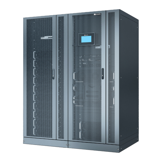
Page 38: Cabinet Description (1200 Kva, Three-Phase Four-Wire)
Configuration type N: no neutral wire 3.3 Cabinet Description (1200 kVA, Three-Phase Four- Wire) 3.3.1 Standard Configuration Figure 3-3 UPS exterior Issue 05 (2021-10-13) Copyright © Huawei Technologies Co., Ltd. - Page 39 (1) SPDs and SPD switches (2) Power modules (3) Surge protection boxes (4) Filler panel (for an optional (5) Control module (6) Intelligent detection card ECM extended subrack) (7) Bypass control module (8) Bypass modules Issue 05 (2021-10-13) Copyright © Huawei Technologies Co., Ltd.
-
Page 40: Top Cabling Configuration
User Manual (100 kVA Power Modules) 3 Product Description 3.3.2 Top Cabling Configuration Figure 3-5 Appearance (1) Top cabling component (optional, including (2) UPS the top frame and transfer copper bar) Issue 05 (2021-10-13) Copyright © Huawei Technologies Co., Ltd. -
Page 41: Bottom Cabling Configuration
User Manual (100 kVA Power Modules) 3 Product Description 3.3.3 Bottom Cabling Configuration Figure 3-6 Appearance (1) Bottom cabling cabinet (2) Transfer copper bar for (3) UPS (optional, including the top bottom cabling (optional) frame) Issue 05 (2021-10-13) Copyright © Huawei Technologies Co., Ltd. -
Page 42: Top Air-Flow Configuration
UPS5000-H-(1200 kVA-1600 kVA) User Manual (100 kVA Power Modules) 3 Product Description 3.3.4 Top Air-Flow Configuration Figure 3-7 Appearance (1) Top air-flow cabinet (optional) (2) UPS Issue 05 (2021-10-13) Copyright © Huawei Technologies Co., Ltd. -
Page 43: Top Air-Flow + Top Cabling Configuration
Figure 3-8 Appearance (1) Top air-flow cabinet (2) Top cabling component (3) UPS (optional) (optional, including the top frame and transfer copper bar) 3.4 Cabinet Description (1200 kVA, Three-Phase Three- Wire) Issue 05 (2021-10-13) Copyright © Huawei Technologies Co., Ltd. -
Page 44: Standard Configuration
(2) Inductor cabinet Figure 3-10 Interior (1) SPDs and SPD switches (2) Power modules (3) Rectifiers (4) Surge protection boxes (5) Control module (6) Main switch QF of the inductor cabinet Issue 05 (2021-10-13) Copyright © Huawei Technologies Co., Ltd. -
Page 45: Top Cabling Configuration
(11) Bypass control module (12) Fans power switches QS1–4 3.4.2 Top Cabling Configuration Figure 3-11 Appearance (1) Top cabling component (2) UPS (3) Inductor cabinet (optional, including the top frame and transfer copper bar) Issue 05 (2021-10-13) Copyright © Huawei Technologies Co., Ltd. -
Page 46: Bottom Cabling Configuration
3 Product Description 3.4.3 Bottom Cabling Configuration Figure 3-12 Appearance (1) Bottom cabling cabinet (optional, including (2) Transfer copper bar for bottom cabling the top frame) (optional) (3) UPS (4) Inductor cabinet Issue 05 (2021-10-13) Copyright © Huawei Technologies Co., Ltd. -
Page 47: Top Air-Flow Configuration
UPS5000-H-(1200 kVA-1600 kVA) User Manual (100 kVA Power Modules) 3 Product Description 3.4.4 Top Air-Flow Configuration Figure 3-13 Appearance (1) Top air-flow cabinet (2) UPS (3) Inductor cabinet (optional) Issue 05 (2021-10-13) Copyright © Huawei Technologies Co., Ltd. -
Page 48: Top Air-Flow + Top Cabling Configuration
(1) Top air-flow cabinet (optional) (2) Top cabling component (optional, including the top frame and transfer copper bar) (3) UPS (4) Inductor cabinet 3.5 Cabinet Description (1600 kVA, Three-Phase Four- Wire) Issue 05 (2021-10-13) Copyright © Huawei Technologies Co., Ltd. -
Page 49: Standard Configuration
(1) Power cabinet 1 (2) Power cabinet 2 (3) Bypass cabinet Figure 3-16 UPS structure with the door open (1) SPDs and SPD switches (2) Power modules (3) Surge protection boxes Issue 05 (2021-10-13) Copyright © Huawei Technologies Co., Ltd. -
Page 50: Top Cabling Configuration
(8) Bypass control module (9) Bypass modules 3.5.2 Top Cabling Configuration Figure 3-17 UPS + top cabling component (1) Top cabling component (optional, including (2) UPS the top frame and transfer copper bar) Issue 05 (2021-10-13) Copyright © Huawei Technologies Co., Ltd. -
Page 51: Bottom Cabling Configuration
Figure 3-18 UPS + bottom cabling cabinet (1) Bottom cabling cabinet (2) Power cabinet 1 (3) Transfer copper bar for (optional, including the top bottom cabling (optional) frame) (4) Power cabinet 2 (5) Bypass cabinet Issue 05 (2021-10-13) Copyright © Huawei Technologies Co., Ltd. -
Page 52: Top Air-Flow Configuration
3.5.5 Top Air-Flow + Top Cabling Configuration Figure 3-20 UPS + top cabling component + top air-flow cabinet (1) Top air-flow cabinet (2) Power cabinet 1 (3) Power cabinet 2 (optional) Issue 05 (2021-10-13) Copyright © Huawei Technologies Co., Ltd. -
Page 53: Cabinet Description (1600 Kva, Three-Phase Three-Wire)
3.6 Cabinet Description (1600 kVA, Three-Phase Three- Wire) 3.6.1 Standard Configuration Figure 3-21 Appearance (1) Power cabinet 1 (2) Power cabinet 2 (3) Bypass cabinet (4) Inductor cabinet Issue 05 (2021-10-13) Copyright © Huawei Technologies Co., Ltd. - Page 54 (5) Main switch QF of the (6) Control module inductor cabinet (7) Intelligent detection board (8) Bypass fan PSU (9) Inductor cabinet fan power switches QS1–4 (10) Bypass modules (11) Bypass control module (12) Fans Issue 05 (2021-10-13) Copyright © Huawei Technologies Co., Ltd.
-
Page 55: Top Cabling Configuration
3.6.2 Top Cabling Configuration Figure 3-23 Appearance (1) Power cabinet 1 (2) Power cabinet 2 (3) Top cabling component (optional, including the top frame and transfer copper bar) (4) Bypass cabinet (5) Inductor cabinet Issue 05 (2021-10-13) Copyright © Huawei Technologies Co., Ltd. -
Page 56: Bottom Cabling Configuration
(1) Bottom cabling cabinet (2) Power cabinet 1 (3) Transfer copper bar for (optional, including the top bottom cabling (optional) frame) (4) Power cabinet 2 (5) Bypass cabinet (6) Inductor cabinet Issue 05 (2021-10-13) Copyright © Huawei Technologies Co., Ltd. -
Page 57: Top Air-Flow Configuration
User Manual (100 kVA Power Modules) 3 Product Description 3.6.4 Top Air-Flow Configuration Figure 3-25 Appearance (1) Top air-flow cabinet (2) Power cabinet 1 (3) Power cabinet 2 (optional) (4) Bypass cabinet (5) Inductor cabinet Issue 05 (2021-10-13) Copyright © Huawei Technologies Co., Ltd. -
Page 58: Top Air-Flow + Top Cabling Configuration
(1) Top air-flow cabinet (2) Power cabinet 1 (3) Power cabinet 2 (optional) (4) Bypass cabinet (5) Top cabling component (6) Inductor cabinet (optional, including the top frame and transfer copper bar) Issue 05 (2021-10-13) Copyright © Huawei Technologies Co., Ltd. -
Page 59: Component Description
(blinking at 0.5 Hz, on for 1s and off for 1s). long ● The inverter is not started (blinking at 0.2 Hz, interv on for 2.5s and off for 2.5s). Issue 05 (2021-10-13) Copyright © Huawei Technologies Co., Ltd. -
Page 60: Bypass Module
The power module overload times out. ● Both active and standby energy control modules (ECMs) in the system are abnormal. ● The system runs abnormally. ● The UPS is transferred to bypass mode manually. Issue 05 (2021-10-13) Copyright © Huawei Technologies Co., Ltd. - Page 61 Fault Steady on A critical alarm is generated for the indicator bypass. There is no critical alarm for the bypass, or the software is being upgraded. Issue 05 (2021-10-13) Copyright © Huawei Technologies Co., Ltd.
-
Page 62: Control Module
Ports are protected by a security mechanism. 4.3.2 ECM ● As a control interface for the entire system, the ECM communicates with each module and provides a bus for communication between the dry contact card Issue 05 (2021-10-13) Copyright © Huawei Technologies Co., Ltd. - Page 63 This ECM is the active ECM. Blinking This ECM is the standby ECM and it is ready. at 0.5 Hz This ECM is not ready or the software of this ECM is being upgraded. Issue 05 (2021-10-13) Copyright © Huawei Technologies Co., Ltd.
-
Page 64: Dry Contact Card
The dry contact card allows the UPS to detect and manage the switch status of the battery system (including the external battery switch) and implement remote emergency power off (EPO). The dry contact card is 0.5 U high and hot- swappable. Issue 05 (2021-10-13) Copyright © Huawei Technologies Co., Ltd. - Page 65 (DG) mode mode ● Open: non-DG Port for signal ground mode BCB_OL Port for monitoring the ● Grounded: BCB Grounde battery circuit breaker (BCB) box connected ● Disconnected: BCB box not connected Issue 05 (2021-10-13) Copyright © Huawei Technologies Co., Ltd.
- Page 66 Port for signal ground is ON. STATUS_0V ● Open: The bypass input circuit breaker is OFF. Port for monitoring the ● Closed: The Closed input AC SPD input AC SPD is normal. Issue 05 (2021-10-13) Copyright © Huawei Technologies Co., Ltd.
-
Page 67: Monitoring Interface Card
● When multiple UPSs are connected in parallel, all dry contact signals to be used need to connect to each UPS. Figure 4-7 Monitoring interface card Issue 05 (2021-10-13) Copyright © Huawei Technologies Co., Ltd. - Page 68 ● Network port for connecting to the web service and for SNMP networking Northbound RS485 ● Supported protocol: Modbus-RTU communicati ● Connects to a northbound network ons port management device or third-party network management device over two wires. Issue 05 (2021-10-13) Copyright © Huawei Technologies Co., Ltd.
- Page 69 ● RS485 cables and FE cables must be shielded cables. Figure 4-8 Figure 4-9 are recommended wiring methods for DO ports. Figure 4-8 Wiring method 1 Figure 4-9 Wiring method 2 Figure 4-10 COM1 port pins Issue 05 (2021-10-13) Copyright © Huawei Technologies Co., Ltd.
- Page 70 Table 4-9 Pin definitions for the COM1 port Description RS485– RS485+ 12V_PORT Figure 4-11 COM2 port pins Table 4-10 Pin definitions for the COM2 port Description RS485+ RS485– RS485+ RS485– CANH0 CANL0 Issue 05 (2021-10-13) Copyright © Huawei Technologies Co., Ltd.
-
Page 71: Intelligent Detection Card
It is 1 U high and supports hot swap. Issue 05 (2021-10-13) Copyright © Huawei Technologies Co., Ltd. - Page 72 ● Signal cables must be double-insulated twisted cables. If the cable length is within 25– 50 m, the cross-sectional area must be 0.5–1.5 mm ● RS485 cables and FE cables must be shielded cables. Issue 05 (2021-10-13) Copyright © Huawei Technologies Co., Ltd.
- Page 73 User Manual (100 kVA Power Modules) 4 Component Description Figure 4-14 COM_OUT port pins Table 4-14 Pin definitions for the COM_OUT port Description RS485+ RS485– RS485+ RS485– CANH CANL Figure 4-15 FE_1 port pins Issue 05 (2021-10-13) Copyright © Huawei Technologies Co., Ltd.
-
Page 74: Surge Protection Box
The MDU allows you to control UPS operations, view the running status and UPS5000 Monitoring Module User alarms, and set parameters. For details, see the Manual . Dimensions (H x W x D): 175 mm x 264 mm x 40 mm Issue 05 (2021-10-13) Copyright © Huawei Technologies Co., Ltd. - Page 75 The UPS is running properly or a warning has been generated. The MDU is powered off. NO TE The indicator on the MDU panel is yellow when the bypass supplies power in non-ECO mode. Figure 4-18 MDU ports Issue 05 (2021-10-13) Copyright © Huawei Technologies Co., Ltd.
- Page 76 View or obtain UPS running information during inspection. NOTE Only Huawei service engineers or authorized service engineers are allowed to use the WiFi module. To ensure security, remove the WiFi module immediately after use. ● Insert a USB flash drive to import and export configuration files, export run logs, and upgrade software.
-
Page 77: Optional Components
5 m/10 m/15 m Connects UPSs in parallel. Top air-flow cabinet Applies to the top airflow scenario. Rear copper bar Protects copper bars at the rear of the protection cabinet. component Issue 05 (2021-10-13) Copyright © Huawei Technologies Co., Ltd. -
Page 78: Dry Contact Extended Card
NO TE The ECM extended subrack does not support onsite installation. If you require this optional component, inform Huawei when you purchase the UPS so that Huawei can install the subrack before delivery. 5.2 Dry Contact Extended Card The dry contact extended card provides five groups of electric relay output ports for dry contact signals and five groups of signal input ports to implement various alarm and control functions as required. - Page 79 Door alarm and Water alarm. The default value is None. ● DI ports detect input dry contact signals which DI_3 are passive signals. DI_4 DI_5 The following wiring methods are recommended for DO ports. Issue 05 (2021-10-13) Copyright © Huawei Technologies Co., Ltd.
-
Page 80: Backfeed Protection Card
When energy backfeed occurs, the backfeed protection card sends signals to trigger alarm signals or quickly disconnect the feedback loop. The card is hot swappable. Figure 5-4 Appearance Figure 5-5 Ports on the backfeed protection card Issue 05 (2021-10-13) Copyright © Huawei Technologies Co., Ltd. -
Page 81: Bcb Box
RSV_NO Reserved (reserved) RSV_COM RSV_NC 5.4 BCB Box The BCB box controls the connection between battery strings and the UPS, and supports overload protection, short circuit protection, and remote trip control. Issue 05 (2021-10-13) Copyright © Huawei Technologies Co., Ltd. -
Page 82: Ambient T/H Sensor
The ambient T/H sensor can also be used as a battery temperature sensor. The monitoring module distinguishes these two types of sensors through their DIP switch settings. Issue 05 (2021-10-13) Copyright © Huawei Technologies Co., Ltd. -
Page 83: Top Air-Flow Cabinet
T/H sensors need to be cascaded, connect the RJ11 port on each T/H sensor. Figure 5-8 RJ11 port Table 5-4 Pins on the RJ11 port Pin No. Signal S_RS485B_R– S_RS485B_R+ 12V_OUT 5.6 Top Air-Flow Cabinet Applies to the top airflow scenario. Issue 05 (2021-10-13) Copyright © Huawei Technologies Co., Ltd. -
Page 84: Bottom Cabling Cabinet
Cabinet dimensions (H x W x D): 2000 mm x 400 mm x 1000 mm (excluding the top frame and copper bars) For details about the appearance of the combination with the UPS, see the section about cabinet description. Issue 05 (2021-10-13) Copyright © Huawei Technologies Co., Ltd. -
Page 85: Rear Copper Bar Protection Component
Figure 5-10 Cabinet 5.8 Rear Copper Bar Protection Component Protects copper bars at the rear of the cabinet. Figure 5-11 Appearance 5.9 Top Cabling Component Applies to the top cabling scenario. Issue 05 (2021-10-13) Copyright © Huawei Technologies Co., Ltd. - Page 86 User Manual (100 kVA Power Modules) 5 Optional Components Figure 5-12 Copper bar assembly (1200 kVA) Figure 5-13 Top frame (1200 kVA) Figure 5-14 Copper bar assembly (1600 kVA) Figure 5-15 Top frame (1600 kVA) Issue 05 (2021-10-13) Copyright © Huawei Technologies Co., Ltd.
-
Page 87: Inductor Cabinet
(2) Main switch QF of the inductor cabinet (3) Inductor cabinet fan power switches QS1–4 (4) Fans 5.10.1 Rectifier A rectifier converts AC input power into stable DC power for the fan in the inductor cabinet. Issue 05 (2021-10-13) Copyright © Huawei Technologies Co., Ltd. - Page 88 ● The rectifier has generated a shutdown alarm for protection due to ambient overtemperature or undertemperature. AC input overvoltage or undervoltage protection has been triggered. The rectifier is hibernating. Issue 05 (2021-10-13) Copyright © Huawei Technologies Co., Ltd.
- Page 89 The rectifier has no output due to an internal fault. Table 5-7 Specifications Item Specifications Dimensions (H x 40.8 mm x 95.5 mm x 208 mm W x D) Weight ≤ 1.5 kg Issue 05 (2021-10-13) Copyright © Huawei Technologies Co., Ltd.
-
Page 90: Installation
UPS output power cables. 6.1.1 Site 6.1.1.1 Installation Environment ● Do not install the UPS in a high-temperature, low-temperature, or damp place that is beyond the technical specifications. Issue 05 (2021-10-13) Copyright © Huawei Technologies Co., Ltd. -
Page 91: Installation Clearances (Three-Phase Four-Wire)
Reserve a clearance of at least 800 mm if you need to perform operations at the rear of the cabinet. – If the top air-flow cabinet is configured, no space needs to be reserved at the rear. Issue 05 (2021-10-13) Copyright © Huawei Technologies Co., Ltd. - Page 92 UPS5000-H-(1200 kVA-1600 kVA) User Manual (100 kVA Power Modules) 6 Installation Figure 6-1 Space planning for standard configuration (1200 kVA) Figure 6-2 Space planning for top cabling configuration (1200 kVA) Issue 05 (2021-10-13) Copyright © Huawei Technologies Co., Ltd.
- Page 93 UPS5000-H-(1200 kVA-1600 kVA) User Manual (100 kVA Power Modules) 6 Installation Figure 6-3 Space planning for bottom cabling configuration (1200 kVA) Figure 6-4 Space planning for top air-flow configuration (1200 kVA) Issue 05 (2021-10-13) Copyright © Huawei Technologies Co., Ltd.
- Page 94 UPS5000-H-(1200 kVA-1600 kVA) User Manual (100 kVA Power Modules) 6 Installation Figure 6-5 Space planning for top cabling + top air-flow configuration (1200 kVA) Figure 6-6 Space planning for standard configuration (1600 kVA) Issue 05 (2021-10-13) Copyright © Huawei Technologies Co., Ltd.
- Page 95 UPS5000-H-(1200 kVA-1600 kVA) User Manual (100 kVA Power Modules) 6 Installation Figure 6-7 Space planning for top cabling configuration (1600 kVA) Figure 6-8 Space planning for bottom cabling configuration (1600 kVA) Issue 05 (2021-10-13) Copyright © Huawei Technologies Co., Ltd.
-
Page 96: Installation Clearances (Three-Phase Three-Wire)
User Manual (100 kVA Power Modules) 6 Installation Figure 6-9 Space planning for top air-flow configuration (1600 kVA) Figure 6-10 Space planning for top cabling + top air-flow configuration (1600 kVA) 6.1.1.3 Installation Clearances (Three-Phase Three-Wire) Issue 05 (2021-10-13) Copyright © Huawei Technologies Co., Ltd. - Page 97 – If the top air-flow cabinet is configured, no space needs to be reserved at the rear. Figure 6-11 Space planning for standard configuration (1200 kVA) Issue 05 (2021-10-13) Copyright © Huawei Technologies Co., Ltd.
- Page 98 UPS5000-H-(1200 kVA-1600 kVA) User Manual (100 kVA Power Modules) 6 Installation Figure 6-12 Space planning for top cabling configuration (1200 kVA) Figure 6-13 Space planning for bottom cabling configuration (1200 kVA) Issue 05 (2021-10-13) Copyright © Huawei Technologies Co., Ltd.
- Page 99 User Manual (100 kVA Power Modules) 6 Installation Figure 6-14 Space planning for top air-flow configuration (1200 kVA) Figure 6-15 Space planning for top cabling + top air-flow configuration (1200 kVA) Issue 05 (2021-10-13) Copyright © Huawei Technologies Co., Ltd.
- Page 100 UPS5000-H-(1200 kVA-1600 kVA) User Manual (100 kVA Power Modules) 6 Installation Figure 6-16 Space planning for standard configuration (1600 kVA) Figure 6-17 Space planning for top cabling configuration (1600 kVA) Issue 05 (2021-10-13) Copyright © Huawei Technologies Co., Ltd.
- Page 101 UPS5000-H-(1200 kVA-1600 kVA) User Manual (100 kVA Power Modules) 6 Installation Figure 6-18 Space planning for bottom cabling configuration (1600 kVA) Figure 6-19 Space planning for top air-flow configuration (1600 kVA) Issue 05 (2021-10-13) Copyright © Huawei Technologies Co., Ltd.
-
Page 102: Tools And Instruments
Table 6-1 Tools and instruments Tools and Instruments Electric pallet Manual pallet Step ladder Rubber mallet truck truck Hammer drill Hand-held Hole saw Heat gun (with a Φ16 drill electric drill bit) Issue 05 (2021-10-13) Copyright © Huawei Technologies Co., Ltd. - Page 103 ESD gloves Protective gloves Insulation gloves Insulated protective shoes Torque Cable cutter Brush Flat-head screwdriver screwdriver (2–5 mm) Phillips Insulated torque Heat-shrink Insulated screwdriver wrench tubing adjustable wrench (M3/M4/M5/M6/ (M6/M8/M12/ M16) Issue 05 (2021-10-13) Copyright © Huawei Technologies Co., Ltd.
-
Page 104: Preparing Power Cables
If the top cabling component and bottom cabling cabinet are not configured, prepare wiring copper bars for mains input, bypass input, and output based on the following drawings and current requirements. Issue 05 (2021-10-13) Copyright © Huawei Technologies Co., Ltd. - Page 105 Copper bars must not be exposed.) (2) Space for the dense busway Issue 05 (2021-10-13) Copyright © Huawei Technologies Co., Ltd.
- Page 106 Figure 6-23 Front view of the distance between copper bars on the top (1200 kVA; unit: mm) Figure 6-24 Front view of the distance between copper bars on the top (1600 kVA; unit: mm) Issue 05 (2021-10-13) Copyright © Huawei Technologies Co., Ltd.
- Page 107 Figure 6-25 Input and output copper bar specifications (1200 kVA, unit: mm) Figure 6-26 Input and output copper bar specifications (1600 kVA, unit: mm) Figure 6-27 Battery copper bar wiring holes (1200 kVA, unit: mm) Issue 05 (2021-10-13) Copyright © Huawei Technologies Co., Ltd.
- Page 108 6 x 240 6 x 240 area 5 x 240 5 x 240 6 x 240 6 x 240 2 x 240 2 x 240 2 x 240 2 x 240 Issue 05 (2021-10-13) Copyright © Huawei Technologies Co., Ltd.
- Page 109 (SmartLi) Maximum battery 2347 2607 2868 3129 discharge current Recommended For details, see the IEC-60364-5-52 specifications and SmartLi User Manual . cross-sectional area Equipotentia Recommended l ground cross-sectional point area (mm Issue 05 (2021-10-13) Copyright © Huawei Technologies Co., Ltd.
- Page 110 8 x 240 nded 8 x 240 8 x 240 8 x 240 8 x 240 cross- sectional 2 x 240 2 x 240 2 x 240 2 x 240 area Issue 05 (2021-10-13) Copyright © Huawei Technologies Co., Ltd.
- Page 111 IEC 60364-5-52). – The ambient temperature is 30°C. – The AC voltage loss is less than 3%, and the DC voltage loss is less than – Conductor insulation: PVC insulation Issue 05 (2021-10-13) Copyright © Huawei Technologies Co., Ltd.
- Page 112 2500 3000 3000 circuit A/3P A/3P A/3P A/3P A/3P A/3P A/3P A/3P breaker a: recommended model when the short-circuit current where the circuit breaker is located is less than 65 kA Issue 05 (2021-10-13) Copyright © Huawei Technologies Co., Ltd.
-
Page 113: Unpacking
Step 3 After confirming that the UPS is intact, remove the bolts that secure the UPS to the pallet and remove the UPS from the pallet. Figure 6-29 Unpacking (1600 kVA power cabinet 1) Issue 05 (2021-10-13) Copyright © Huawei Technologies Co., Ltd. -
Page 114: Ups Cable Connection Reference
Step 3 Pull the marked cable out of the cabinet, cut the cable from the marked position, strip the cable, and crimp a terminal. Issue 05 (2021-10-13) Copyright © Huawei Technologies Co., Ltd. -
Page 115: Single Ups Installation (1200 Kva, Three-Phase Four-Wire)
Installation on the Floor NO TICE Ensure that the installation floor is flat. Step 1 Determine the cabinet installation positions on the floor based on the holes in the marking-off template for floor installation. Issue 05 (2021-10-13) Copyright © Huawei Technologies Co., Ltd. - Page 116 NO TICE Knock the expansion bolt into the hole until the expansion sleeve completely fits into the hole. The expansion sleeve must be completely buried under the ground to facilitate subsequent installation. Issue 05 (2021-10-13) Copyright © Huawei Technologies Co., Ltd.
- Page 117 Step 4 Secure the cabinets. Figure 6-34 Securing the cabinets NO TE To meet the requirements of 9-intensity earthquake resistance, tighten 16 screws at the bottom. Step 5 Install anchor baffle plates. Issue 05 (2021-10-13) Copyright © Huawei Technologies Co., Ltd.
- Page 118 ----End Installation on Channel Steel NO TICE ● Huawei does not provide channel steel or expansion bolts used for securing channel steel. It is recommended that the customer purchase at least 50 mm wide channel steel. ● Ensure that the surface of channel steel is level.
-
Page 119: Installing Cables
Figure 6-37 Recommended channel steel dimensions (unit: mm) 6.3.1.2 Installing Cables Context Figure 6-38 Copper bar positions (1) Battery input (2) Mains input (3) Battery PE (4) UPS output (5) Bypass input Issue 05 (2021-10-13) Copyright © Huawei Technologies Co., Ltd. - Page 120 Figure 6-40 Removing the covers Remove the screws that secure the guide rail of the SPD. Place the SPD on the horizontal plate (without removing the cables). Remove the copper bars. Issue 05 (2021-10-13) Copyright © Huawei Technologies Co., Ltd.
- Page 121 Figure 6-41 Removing copper bars Step 3 Install battery cables. NO TE The figure uses the cable connection between the UPS and the SmartLi as an example. Battery cables are connected to each SmartLi. Issue 05 (2021-10-13) Copyright © Huawei Technologies Co., Ltd.
- Page 122 Step 4 Install top supports and covers of the battery terminal protective covers. Figure 6-43 Installing top supports and covers Step 5 Install input and output busbars. Issue 05 (2021-10-13) Copyright © Huawei Technologies Co., Ltd.
- Page 123 ● The figure uses the cable connection between the UPS and the SmartLi as an example. Figure 6-44 Connecting a signal cable between the UPS and the SmartLi (only for SmartLi 2.0) (1) Monitoring interface unit in the master SmartLi cabinet ----End Issue 05 (2021-10-13) Copyright © Huawei Technologies Co., Ltd.
-
Page 124: Installation In Top Cabling Configuration
Procedure Step 1 Install conversion copper bars from right to left and remove the left and right connecting kits from the top of the cabinets. Figure 6-46 Installing conversion copper bars Issue 05 (2021-10-13) Copyright © Huawei Technologies Co., Ltd. - Page 125 Remove the copper bars. Reinstall the SPD. NO TICE The mains and bypass copper bars are heavy. To prevent personal injury or device damage, arrange for two persons to work together. Issue 05 (2021-10-13) Copyright © Huawei Technologies Co., Ltd.
- Page 126 The number and colors of cables are for reference only. The figure uses the cable connection between the UPS and the SmartLi as an example. Connect battery cables to each SmartLi. Issue 05 (2021-10-13) Copyright © Huawei Technologies Co., Ltd.
- Page 127 (1) Connect the ground cable of the battery string or its BBB box to the battery PE of the UPS or the ground bar in the equipment room based on the site survey. Step 5 Install top frames (No. 14–17). Figure 6-52 Installing top frames Step 6 Install top covers. Issue 05 (2021-10-13) Copyright © Huawei Technologies Co., Ltd.
- Page 128 (Connection required only for SmartLi 2.0) If the UPS needs to connect to the SmartLi, connect the COM port on the monitoring interface unit in the master SmartLi cabinet to the COM2 port on the monitoring interface card. Issue 05 (2021-10-13) Copyright © Huawei Technologies Co., Ltd.
-
Page 129: Installation In Bottom Cabling Configuration
Installation on the Floor NO TICE Ensure that the installation floor is flat. Step 1 Determine the cabinet installation positions on the floor based on the holes in the marking-off template for floor installation. Issue 05 (2021-10-13) Copyright © Huawei Technologies Co., Ltd. - Page 130 NO TICE Knock the expansion bolt into the hole until the expansion sleeve completely fits into the hole. The expansion sleeve must be completely buried under the ground to facilitate subsequent installation. Issue 05 (2021-10-13) Copyright © Huawei Technologies Co., Ltd.
- Page 131 Step 6 Combine the bottom cabling cabinet with other cabinets in the sequence of bottom, top, and middle, and remove the connecting kits on the top of the left and right sides. Figure 6-58 Combining the bottom cabling cabinet Step 7 Secure the cabinets. Issue 05 (2021-10-13) Copyright © Huawei Technologies Co., Ltd.
- Page 132 Figure 6-59 Securing the cabinets Step 8 Install the removed side panels on both sides of the bottom cabling cabinet. Step 9 Install anchor baffle plates. Figure 6-60 Installing anchor baffle plates ----End Issue 05 (2021-10-13) Copyright © Huawei Technologies Co., Ltd.
- Page 133 6 Installation Installation on Channel Steel NO TICE ● Huawei does not provide channel steel or expansion bolts used for securing channel steel. It is recommended that the customer purchase at least 50 mm wide channel steel. ● Ensure that the surface of channel steel is level.
-
Page 134: Installing Copper Bars And Cables
Step 1 Remove the top covers from the bottom cabling cabinet and the battery copper bars. Figure 6-64 Removing the covers and battery copper bars Step 2 Install epoxy boards (No. 1 to 8). Issue 05 (2021-10-13) Copyright © Huawei Technologies Co., Ltd. - Page 135 Figure 6-66 Installing copper bars Step 4 Install bypass input copper bars (No. 20 to 23) and output copper bars (No. 24 to 27) from right to left. Issue 05 (2021-10-13) Copyright © Huawei Technologies Co., Ltd.
- Page 136 Figure 6-67 Installing copper bars Step 5 Remove the bottom cabling cover from the bottom cabling cabinet. Step 6 Install equipotential ground cable for cabinets. Figure 6-68 Installing equipotential ground cable for cabinets Issue 05 (2021-10-13) Copyright © Huawei Technologies Co., Ltd.
- Page 137 Figure 6-71 Removing copper bars Remove the screws that secure the guide rail of the SPD. Place the SPD on the horizontal plate (without removing the cables). Remove the copper bars. Reinstall the SPD. Issue 05 (2021-10-13) Copyright © Huawei Technologies Co., Ltd.
- Page 138 If the mains input and bypass input share a power source, you do not need to remove the copper bar between the mains and bypass input terminals or connect the bypass input power cable. Step 9 Install battery cables. Issue 05 (2021-10-13) Copyright © Huawei Technologies Co., Ltd.
- Page 139 ● Do not bind signal cables and power cables together. ● RS485 cables and FE cables must be shielded cables. ● The figure uses the cable connection between the UPS and the SmartLi as an example. Issue 05 (2021-10-13) Copyright © Huawei Technologies Co., Ltd.
- Page 140 Figure 6-74 Connecting a signal cable between the UPS and the SmartLi (only for SmartLi 2.0) (1) Monitoring interface unit in the master SmartLi cabinet Step 11 Install top frames. Figure 6-75 Installing top frames Step 12 Install the front and rear mounting plates. Issue 05 (2021-10-13) Copyright © Huawei Technologies Co., Ltd.
-
Page 141: Installation In Top Air-Flow Configuration
Installation on the Floor NO TICE Ensure that the installation floor is flat. Step 1 Determine the positions for installing cabinets on the mounting surface based on holes in the marking-off template. Issue 05 (2021-10-13) Copyright © Huawei Technologies Co., Ltd. - Page 142 Remove the rear door panels from the UPS cabinets. Secure the PC panels to the inner side of the rear door panel from the outer side of the rear door using plastic rivets. Issue 05 (2021-10-13) Copyright © Huawei Technologies Co., Ltd.
- Page 143 Remove the door sills from the rear of the UPS cabinets. Figure 6-80 Removing door sills (rear view of the cabinets) Install the accessories of the top air-flow cabinet. Issue 05 (2021-10-13) Copyright © Huawei Technologies Co., Ltd.
- Page 144 Remove the left panel from the UPS cabinet. Move the top air-flow cabinet to the installation position and secure it. Remove the power distribution cover and bottom cover from the top air- flow cabinet. Issue 05 (2021-10-13) Copyright © Huawei Technologies Co., Ltd.
- Page 145 UPS5000-H-(1200 kVA-1600 kVA) User Manual (100 kVA Power Modules) 6 Installation Figure 6-83 Removing covers Install connecting kits from the bottom to the middle. Figure 6-84 Installing connecting kits Tighten the anchor bolts. Issue 05 (2021-10-13) Copyright © Huawei Technologies Co., Ltd.
- Page 146 Step 5 Install the removed side panel on the side of the top air-flow cabinet. Step 6 Install the side and front anchor baffle plates. Figure 6-86 Installing anchor baffle plates ----End Issue 05 (2021-10-13) Copyright © Huawei Technologies Co., Ltd.
- Page 147 6 Installation Installation on Channel Steel NO TICE ● Huawei does not provide channel steel or expansion bolts used for securing channel steel. It is recommended that the customer purchase at least 50 mm wide channel steel. ● Ensure that the surface of channel steel is level.
-
Page 148: Installing Cables
6.3.5 Installation in Top Cabling + Top Air-Flow Configuration ● If both the top cabling component and the top air-flow cabinet are configured, cabinets can be installed against a wall and cables can be routed from the top. Issue 05 (2021-10-13) Copyright © Huawei Technologies Co., Ltd. -
Page 149: Installing Cabinets
Installing Cables. Install the top frame for the top air-flow cabinet. Figure 6-90 Installing a top frame Install the mounting plates for the top air-flow cabinet. Figure 6-91 Installing mounting plates Issue 05 (2021-10-13) Copyright © Huawei Technologies Co., Ltd. -
Page 150: Single Ups Installation (1200 Kva, Three-Phase Three-Wire)
Step 2 Use a hammer drill to drill holes for installing expansion bolts and then install expansion sleeves in the holes. Drill a hole into the concrete floor using a hammer drill. The hole depth ranges from 52 mm to 60 mm. Issue 05 (2021-10-13) Copyright © Huawei Technologies Co., Ltd. - Page 151 (5) Expansion nut (6) Concrete floor Step 3 Move the cabinets to the installation positions. Step 4 Combine the inductor cabinet with other cabinets. Remove the right panel from the UPS cabinet. Issue 05 (2021-10-13) Copyright © Huawei Technologies Co., Ltd.
- Page 152 Combine the inductor cabinet with other cabinets in the sequence of bottom, top, and middle, reinstall the rear door panel of the inductor cabinet, and install the removed side panel to the side of the inductor cabinet. Issue 05 (2021-10-13) Copyright © Huawei Technologies Co., Ltd.
- Page 153 Step 5 Secure the cabinets. Figure 6-97 Securing the cabinets NO TE To meet the requirements of 9-intensity earthquake resistance, tighten 24 screws at the bottom. Step 6 Install anchor baffle plates. Issue 05 (2021-10-13) Copyright © Huawei Technologies Co., Ltd.
- Page 154 ----End Installation on Channel Steel NO TICE ● Huawei does not provide channel steel or expansion bolts used for securing channel steel. It is recommended that the customer purchase at least 50 mm wide channel steel. ● Ensure that the surface of channel steel is level.
-
Page 155: Installing Rectifiers In The Inductor Cabinet
Insert the rectifier into the slot and push it along the guide rails until it is in position. Push the handle in place and lock it. Push the locking latch rightwards to secure the handle. Install baffle plates for the vacant slots. Issue 05 (2021-10-13) Copyright © Huawei Technologies Co., Ltd. -
Page 156: Installing Cables
(3) Battery PE (4) UPS output (5) Bypass input NO TE The number and colors of cables in the figures are for reference only. Procedure Step 1 Install equipotential ground cable for cabinets. Issue 05 (2021-10-13) Copyright © Huawei Technologies Co., Ltd. - Page 157 ● Cables must be bound to the nearest beam or cable bridge according to the route shown in the figure. ● One power source Figure 6-104 Removing the cover Issue 05 (2021-10-13) Copyright © Huawei Technologies Co., Ltd.
- Page 158 User Manual (100 kVA Power Modules) 6 Installation Figure 6-105 Installing cables (1) Side view of the UPS (2) Power cable hole (3) Signal cable hole ● Two power sources Figure 6-106 Removing the cover Issue 05 (2021-10-13) Copyright © Huawei Technologies Co., Ltd.
- Page 159 (2) Power cable hole (3) Signal cable hole Step 3 Install signal cables between the UPS and the inductor cabinet. NO TICE Do not bind signal cables and power cables together. Issue 05 (2021-10-13) Copyright © Huawei Technologies Co., Ltd.
- Page 160 (1) Connect the ground cable of the battery string or its BBB box to the battery PE of the UPS or the ground bar in the equipment room based on the site survey. Step 5 Install top supports and covers of the battery terminal protective covers. Issue 05 (2021-10-13) Copyright © Huawei Technologies Co., Ltd.
- Page 161 ● Do not bind signal cables and power cables together. ● RS485 cables and FE cables must be shielded cables. ● The figure uses the cable connection between the UPS and the SmartLi as an example. Issue 05 (2021-10-13) Copyright © Huawei Technologies Co., Ltd.
-
Page 162: Installation In Top Cabling Configuration
Step 1 Determine the cabinet installation positions on the floor based on the holes in the marking-off template for floor installation. NO TE ● A: mounting holes on the channel steel ● B: mounting holes on the floor Issue 05 (2021-10-13) Copyright © Huawei Technologies Co., Ltd. - Page 163 The expansion sleeve must be completely buried under the ground to facilitate subsequent installation. Figure 6-114 Drilling holes and installing expansion sleeves (1) M12 bolt (2) Spring washer (3) Flat washer Issue 05 (2021-10-13) Copyright © Huawei Technologies Co., Ltd.
- Page 164 Figure 6-116 Opening the front covers, and removing the rear door panel and top connecting kits Issue 05 (2021-10-13) Copyright © Huawei Technologies Co., Ltd.
- Page 165 Figure 6-117 Installing the connecting kits and reinstalling the rear door panel and side panel Step 5 Secure the cabinets. Figure 6-118 Securing the cabinets NO TE To meet the requirements of 9-intensity earthquake resistance, tighten 24 screws at the bottom. Issue 05 (2021-10-13) Copyright © Huawei Technologies Co., Ltd.
- Page 166 ----End Installation on Channel Steel NO TICE ● Huawei does not provide channel steel or expansion bolts used for securing channel steel. It is recommended that the customer purchase at least 50 mm wide channel steel. ● Ensure that the surface of channel steel is level.
-
Page 167: Installing Rectifiers In The Inductor Cabinet
Insert the rectifier into the slot and push it along the guide rails until it is in position. Push the handle in place and lock it. Push the locking latch rightwards to secure the handle. Install baffle plates for the vacant slots. Issue 05 (2021-10-13) Copyright © Huawei Technologies Co., Ltd. -
Page 168: Installing Copper Bars And Cables
The number and colors of cables in the figures are for reference only. Procedure Step 1 Install conversion copper bars from right to left and remove the left and right connecting kits from the top of the cabinets. Issue 05 (2021-10-13) Copyright © Huawei Technologies Co., Ltd. - Page 169 ● Cables must be bound to the nearest beam or cable bridge according to the route shown in the figure. ● One power source Issue 05 (2021-10-13) Copyright © Huawei Technologies Co., Ltd.
- Page 170 Figure 6-126 Removing the cover Figure 6-127 Installing cables (1) Side view of the UPS (2) Power cable hole (3) Signal cable hole ● Two power sources Figure 6-128 Removing the cover Issue 05 (2021-10-13) Copyright © Huawei Technologies Co., Ltd.
- Page 171 (2) Power cable hole (3) Signal cable hole Step 4 Install signal cables between the UPS and the inductor cabinet. NO TICE Do not bind signal cables and power cables together. Issue 05 (2021-10-13) Copyright © Huawei Technologies Co., Ltd.
- Page 172 (1) Power cable hole (2) Signal cable hole Step 5 Install input and output AC power cables. ● One power source Figure 6-132 Installing AC power cables ● Two power sources Issue 05 (2021-10-13) Copyright © Huawei Technologies Co., Ltd.
- Page 173 (1) Connect the ground cable of the battery string or its BBB box to the battery PE of the UPS or the ground bar in the equipment room based on the site survey. Step 7 Install UPS top frames (No. 14–17). Issue 05 (2021-10-13) Copyright © Huawei Technologies Co., Ltd.
- Page 174 User Manual (100 kVA Power Modules) 6 Installation Figure 6-135 Installing top frames Step 8 Install the top frame for the inductor cabinet. Figure 6-136 Installing the top frame Step 9 Install top covers. Issue 05 (2021-10-13) Copyright © Huawei Technologies Co., Ltd.
- Page 175 Separate the mains input cables, bypass input cables, and output cables by using top beams. Step 10 Install the UPS front and rear mounting plates. Figure 6-138 Installing mounting plates Step 11 Install the front and rear mounting plates for the inductor cabinet. Issue 05 (2021-10-13) Copyright © Huawei Technologies Co., Ltd.
- Page 176 ● Do not bind signal cables and power cables together. ● RS485 cables and FE cables must be shielded cables. ● The figure uses the cable connection between the UPS and the SmartLi as an example. Issue 05 (2021-10-13) Copyright © Huawei Technologies Co., Ltd.
-
Page 177: Installation In Bottom Cabling Configuration
Step 1 Determine the cabinet installation positions on the floor based on the holes in the marking-off template for floor installation. NO TE ● A: mounting holes on the channel steel ● B: mounting holes on the floor Issue 05 (2021-10-13) Copyright © Huawei Technologies Co., Ltd. - Page 178 NO TICE Knock the expansion bolt into the hole until the expansion sleeve completely fits into the hole. The expansion sleeve must be completely buried under the ground to facilitate subsequent installation. Issue 05 (2021-10-13) Copyright © Huawei Technologies Co., Ltd.
- Page 179 Figure 6-143 Combining the bottom cabling cabinet Step 7 Install one removed side panel on the left side of the bottom cabling cabinet. Issue 05 (2021-10-13) Copyright © Huawei Technologies Co., Ltd.
- Page 180 There are sheet metal stiffeners at the bottom of the inductor cabinet. After the pallet is removed, the pallet truck cannot transport the inductor cabinet from the front. Therefore, reserve space on the side of the inductor cabinet or use other transportation methods. Issue 05 (2021-10-13) Copyright © Huawei Technologies Co., Ltd.
- Page 181 User Manual (100 kVA Power Modules) 6 Installation Figure 6-145 Installing the connecting kits and reinstalling the rear door panel Step 9 Secure the cabinets. Figure 6-146 Securing the cabinets Step 10 Install anchor baffle plates. Issue 05 (2021-10-13) Copyright © Huawei Technologies Co., Ltd.
- Page 182 ----End Installation on Channel Steel NO TICE ● Huawei does not provide channel steel or expansion bolts used for securing channel steel. It is recommended that the customer purchase at least 50 mm wide channel steel. ● Ensure that the surface of channel steel is level.
-
Page 183: Installing Rectifiers In The Inductor Cabinet
Insert the rectifier into the slot and push it along the guide rails until it is in position. Push the handle in place and lock it. Push the locking latch rightwards to secure the handle. Install baffle plates for the vacant slots. Issue 05 (2021-10-13) Copyright © Huawei Technologies Co., Ltd. -
Page 184: Installing Copper Bars And Cables
NO TE The number and colors of cables in the figures are for reference only. Procedure Step 1 Remove the top covers from the bottom cabling cabinet and the battery copper bars. Issue 05 (2021-10-13) Copyright © Huawei Technologies Co., Ltd. - Page 185 Step 2 Install epoxy boards (No. 1 to 8). Figure 6-153 Installing epoxy boards Step 3 Install batteries (No. 33 to 36) and mains input copper bars (No. 28 to 32 and 40) from right to left. Issue 05 (2021-10-13) Copyright © Huawei Technologies Co., Ltd.
- Page 186 User Manual (100 kVA Power Modules) 6 Installation Figure 6-154 Installing copper bars Step 4 Install bypass input copper bars (No. 20 to 23) and output copper bars (No. 24 to 27) from right to left. Issue 05 (2021-10-13) Copyright © Huawei Technologies Co., Ltd.
- Page 187 Figure 6-155 Installing copper bars Step 5 Remove the bottom cabling cover from the bottom cabling cabinet. Step 6 Install equipotential ground cable for cabinets. Figure 6-156 Installing equipotential ground cable for cabinets Issue 05 (2021-10-13) Copyright © Huawei Technologies Co., Ltd.
- Page 188 Figure 6-157 Removing the cover Figure 6-158 Installing cables (1) Side view of the UPS (2) Power cable hole in the (3) Signal cable hole in the inductor cabinet inductor cabinet Issue 05 (2021-10-13) Copyright © Huawei Technologies Co., Ltd.
- Page 189 Figure 6-159 Removing the cover Figure 6-160 Removing copper bars NO TICE The mains and bypass copper bars are heavy. To prevent personal injury or device damage, arrange for two persons to work together. Issue 05 (2021-10-13) Copyright © Huawei Technologies Co., Ltd.
- Page 190 (5) Signal cable hole in the bottom cabling cabinet cabling cabinet Step 8 Install signal cables between the UPS and the inductor cabinet. NO TICE Do not bind signal cables and power cables together. Issue 05 (2021-10-13) Copyright © Huawei Technologies Co., Ltd.
- Page 191 (4) Signal cable hole in the bottom cabling cabinet cabinet Step 9 Install mains input power cables. Figure 6-163 Installing mains input power cables Step 10 Install bypass input and output power cables. ● Two power sources Issue 05 (2021-10-13) Copyright © Huawei Technologies Co., Ltd.
- Page 192 If the mains input and bypass input share a power source, you do not need to remove the copper bar between the mains and bypass input terminals or connect the bypass input power cable. Step 11 Install battery cables. Figure 6-165 Installing battery cables Issue 05 (2021-10-13) Copyright © Huawei Technologies Co., Ltd.
- Page 193 Figure 6-166 Connecting a signal cable between the UPS and the SmartLi (only for SmartLi 2.0) (1) Monitoring interface unit in the master SmartLi cabinet Step 13 Install the UPS top frame. Issue 05 (2021-10-13) Copyright © Huawei Technologies Co., Ltd.
- Page 194 Figure 6-167 Installing the top frame Step 14 Install the top frame for the inductor cabinet. Figure 6-168 Installing the top frame Step 15 Install the UPS front and rear mounting plates. Issue 05 (2021-10-13) Copyright © Huawei Technologies Co., Ltd.
-
Page 195: Installation In Top Air-Flow Configuration
Step 17 Install UPS top covers. Figure 6-171 Installing covers ----End 6.4.4 Installation in Top Air-Flow Configuration ● If the top air-flow cabinet is configured, installation against a wall is supported. Issue 05 (2021-10-13) Copyright © Huawei Technologies Co., Ltd. -
Page 196: Installing Cabinets
Remove the rear door panels from the UPS cabinets. Secure the PC panels to the inner side of the rear door panel from the outer side of the rear door using plastic rivets. Issue 05 (2021-10-13) Copyright © Huawei Technologies Co., Ltd. - Page 197 Remove the door sills from the rear of the UPS cabinets. Figure 6-174 Removing door sills (rear view of the cabinets) Install the accessories of the top air-flow cabinet. Issue 05 (2021-10-13) Copyright © Huawei Technologies Co., Ltd.
- Page 198 Remove the left panel from the UPS cabinet. Move the top air-flow cabinet to the installation position and secure it. Remove the power distribution cover and bottom cover from the top air- flow cabinet. Issue 05 (2021-10-13) Copyright © Huawei Technologies Co., Ltd.
- Page 199 UPS5000-H-(1200 kVA-1600 kVA) User Manual (100 kVA Power Modules) 6 Installation Figure 6-177 Removing covers Install connecting kits from the bottom to the middle. Figure 6-178 Installing connecting kits Tighten the anchor bolts. Issue 05 (2021-10-13) Copyright © Huawei Technologies Co., Ltd.
- Page 200 Step 5 Combine the inductor cabinet with other cabinets. Remove the right cover from the UPS cabinet. Figure 6-180 Removing the side panel Open the power distribution covers in the front of the inductor cabinet. Issue 05 (2021-10-13) Copyright © Huawei Technologies Co., Ltd.
- Page 201 Therefore, reserve space on the side of the inductor cabinet or use other transportation methods. Figure 6-182 Installing the connecting kits and side panel Issue 05 (2021-10-13) Copyright © Huawei Technologies Co., Ltd.
- Page 202 User Manual (100 kVA Power Modules) 6 Installation Secure the inductor cabinet. Figure 6-183 Securing the inductor cabinet Step 6 Install the side and front anchor baffle plates. Figure 6-184 Installing anchor baffle plates ----End Issue 05 (2021-10-13) Copyright © Huawei Technologies Co., Ltd.
- Page 203 6 Installation Installation on Channel Steel NO TICE ● Huawei does not provide channel steel or expansion bolts used for securing channel steel. It is recommended that the customer purchase at least 50 mm wide channel steel. ● Ensure that the surface of channel steel is level.
-
Page 204: Installing Rectifiers In The Inductor Cabinet
Insert the rectifier into the slot and push it along the guide rails until it is in position. Push the handle in place and lock it. Push the locking latch rightwards to secure the handle. Install baffle plates for the vacant slots. Issue 05 (2021-10-13) Copyright © Huawei Technologies Co., Ltd. -
Page 205: Installing Cables
Step 3 Remove an accessory cover from the top of the top air-flow cabinet. Step 4 Connect the power cable to the 380~480V System port on the UPS and the signal cable to the XS2 port. Issue 05 (2021-10-13) Copyright © Huawei Technologies Co., Ltd. -
Page 206: Installation In Top Cabling + Top Air-Flow Configuration
Insert the rectifier into the slot and push it along the guide rails until it is in position. Push the handle in place and lock it. Push the locking latch rightwards to secure the handle. Issue 05 (2021-10-13) Copyright © Huawei Technologies Co., Ltd. -
Page 207: Installing Copper Bars And Cables
Three-Phase Three-Wire) > Installation in Top Air-Flow Configuration > Installing Cables. Install the top frame for the top air-flow cabinet. Figure 6-190 Installing a top frame Install the mounting plates for the top air-flow cabinet. Issue 05 (2021-10-13) Copyright © Huawei Technologies Co., Ltd. -
Page 208: Single Ups Installation (1600 Kva, Three-Phase Four-Wire)
Step 1 Determine the cabinet installation positions on the floor based on the holes in the marking-off template for floor installation. NO TE ● A: mounting holes on the channel steel ● B: mounting holes on the floor Issue 05 (2021-10-13) Copyright © Huawei Technologies Co., Ltd. - Page 209 NO TICE Knock the expansion bolt into the hole until the expansion sleeve completely fits into the hole. The expansion sleeve must be completely buried under the ground to facilitate subsequent installation. Issue 05 (2021-10-13) Copyright © Huawei Technologies Co., Ltd.
- Page 210 Figure 6-194 Removing the preinstalled screws Step 4 Move the cabinets to the mounting holes. Step 5 Remove the power distribution covers from power cabinets 1 and 2. Figure 6-195 Removing the covers Issue 05 (2021-10-13) Copyright © Huawei Technologies Co., Ltd.
- Page 211 Figure 6-196 Combining cabinets Step 7 Reinstall the UPS rear door panels. Step 8 Secure the cabinets. Figure 6-197 Securing the cabinets Step 9 Install anchor baffle plates. Issue 05 (2021-10-13) Copyright © Huawei Technologies Co., Ltd.
- Page 212 Figure 6-198 Installing anchor baffle plates Step 10 Install the parallel copper bars. Figure 6-199 Installing screws on parallel battery and output copper bars Figure 6-200 Taking out parallel copper bars Issue 05 (2021-10-13) Copyright © Huawei Technologies Co., Ltd.
- Page 213 ----End Installation on Channel Steel NO TICE ● Huawei does not provide channel steel or expansion bolts used for securing channel steel. It is recommended that the customer purchase at least 50 mm wide channel steel. ● Ensure that the surface of channel steel is level.
-
Page 214: Installing Cables
Figure 6-203 Recommended channel steel dimensions (unit: mm) 6.5.1.2 Installing Cables Context Figure 6-204 Copper bar positions (1) Battery input (2) Battery PE (3) Mains input (4) UPS output (5) Bypass input Issue 05 (2021-10-13) Copyright © Huawei Technologies Co., Ltd. - Page 215 Cable 3 Power cabinet One end of Bypass the NTC cable cabinet is preinstalled. The other end is reserved inside the cabinet and needs to be connected to the bypass cabinet. Issue 05 (2021-10-13) Copyright © Huawei Technologies Co., Ltd.
- Page 216 ● Perform this step only when the mains input and bypass input use different power sources. ● The mains and bypass copper bars are heavy. To prevent personal injury or device damage, arrange for two persons to work together. Issue 05 (2021-10-13) Copyright © Huawei Technologies Co., Ltd.
- Page 217 (1) Connect the ground cable of the battery string or its BBB box to the battery PE of the UPS or the ground bar in the equipment room based on the site survey. Step 6 Install top supports and covers of the battery terminal protective covers. Issue 05 (2021-10-13) Copyright © Huawei Technologies Co., Ltd.
- Page 218 ● Do not bind signal cables and power cables together. ● RS485 cables and FE cables must be shielded cables. ● The figure uses the cable connection between the UPS and the SmartLi as an example. Issue 05 (2021-10-13) Copyright © Huawei Technologies Co., Ltd.
-
Page 219: Installation In Top Cabling Configuration
Cables can be routed from the top if the optional top cabling component is configured. 6.5.2.1 Installing Cabinets Install cabinets by referring to Single UPS Installation (1600 kVA, Three-Phase Four-Wire) > Installation in Standard Configuration > Installing Cabinets. Issue 05 (2021-10-13) Copyright © Huawei Technologies Co., Ltd. -
Page 220: Installing Copper Bars And Cables
The number and colors of cables in the following figures are for reference only. Procedure Step 1 Remove the power distribution cover from the bypass cabinet. Figure 6-213 Removing the cover Step 2 Install signal cables inside the cabinets. Issue 05 (2021-10-13) Copyright © Huawei Technologies Co., Ltd. - Page 221 Figure 6-214 Installing signal cables inside the cabinets Step 3 Install conversion copper bars from right to left and remove the left and right connecting kits from the top of the cabinets. Issue 05 (2021-10-13) Copyright © Huawei Technologies Co., Ltd.
- Page 222 Remove the copper bars between the mains and bypass input wiring terminals. NO TICE The mains and bypass copper bars are heavy. To prevent personal injury or device damage, arrange for two persons to work together. Issue 05 (2021-10-13) Copyright © Huawei Technologies Co., Ltd.
- Page 223 Step 6 Install AC output power cables. Figure 6-219 Installing AC output power cables Issue 05 (2021-10-13) Copyright © Huawei Technologies Co., Ltd.
- Page 224 Step 8 Install top frames (No. 14–17). Figure 6-221 Installing the top frame Step 9 Install top covers. Issue 05 (2021-10-13) Copyright © Huawei Technologies Co., Ltd.
- Page 225 (Connection required only for SmartLi 2.0) If the UPS needs to connect to the SmartLi, connect the COM port on the monitoring interface unit in the master SmartLi cabinet to the COM2 port on the monitoring interface card. Issue 05 (2021-10-13) Copyright © Huawei Technologies Co., Ltd.
-
Page 226: Installation In Bottom Cabling Configuration
Installation on the Floor NO TICE Ensure that the installation floor is flat. Step 1 Determine the cabinet installation positions on the floor based on the holes in the marking-off template for floor installation. Issue 05 (2021-10-13) Copyright © Huawei Technologies Co., Ltd. - Page 227 NO TICE Knock the expansion bolt into the hole until the expansion sleeve completely fits into the hole. The expansion sleeve must be completely buried under the ground to facilitate subsequent installation. Issue 05 (2021-10-13) Copyright © Huawei Technologies Co., Ltd.
- Page 228 Figure 6-227 Removing the preinstalled screws Move the UPS cabinets to the installation positions. Remove the power distribution covers from power cabinets 1 and 2. Figure 6-228 Removing the covers Issue 05 (2021-10-13) Copyright © Huawei Technologies Co., Ltd.
- Page 229 Remove the side panels from power cabinet 1 and the bypass cabinet. Move the bottom cabling cabinet to the installation position. Remove the front panel of the bottom cabling cabinet and combine the bottom cabling cabinet. Issue 05 (2021-10-13) Copyright © Huawei Technologies Co., Ltd.
- Page 230 Step 4 Secure the cabinets. Figure 6-231 Securing the cabinets Step 5 Install the removed side panels on both sides of the bottom cabling cabinet. Step 6 Install anchor baffle plates. Issue 05 (2021-10-13) Copyright © Huawei Technologies Co., Ltd.
- Page 231 Figure 6-232 Installing anchor baffle plates Step 7 Install the parallel copper bars. Figure 6-233 Installing screws on parallel battery and output copper bars Figure 6-234 Taking out parallel copper bars Issue 05 (2021-10-13) Copyright © Huawei Technologies Co., Ltd.
- Page 232 ----End Installation on Channel Steel NO TICE ● Huawei does not provide channel steel or expansion bolts used for securing channel steel. It is recommended that the customer purchase at least 50 mm wide channel steel. ● Ensure that the surface of channel steel is level.
-
Page 233: Installing Copper Bars And Cables
Figure 6-237 Recommended channel steel dimensions (unit: mm) 6.5.3.2 Installing Copper Bars and Cables Context Figure 6-238 Copper bar positions (1) Battery input (2) Battery PE (3) Mains input (4) UPS output (5) Bypass input Issue 05 (2021-10-13) Copyright © Huawei Technologies Co., Ltd. - Page 234 Cable 3 Power cabinet One end of Bypass the NTC cable cabinet is preinstalled. The other end is reserved inside the cabinet and needs to be connected to the bypass cabinet. Issue 05 (2021-10-13) Copyright © Huawei Technologies Co., Ltd.
- Page 235 Figure 6-241 Removing the covers, connecting kits, and battery copper bars Step 4 Install epoxy boards (No. 11 to 14 and 16 to 20). Figure 6-242 Installing epoxy boards Step 5 Install battery copper bars (No. 65 and 67 to 69). Issue 05 (2021-10-13) Copyright © Huawei Technologies Co., Ltd.
- Page 236 Step 6 Install mains input copper bars (No. 55 to 59, 61 to 64, and 70) from right to left. Figure 6-244 Installing mains input copper bars Step 7 Install bypass input copper bars (No. 40 to 47) and output copper bars (No. 48 to 54) from right to left. Issue 05 (2021-10-13) Copyright © Huawei Technologies Co., Ltd.
- Page 237 Figure 6-245 Installing bypass input and output copper bars Step 8 Install epoxy boards. Figure 6-246 Installing epoxy boards Step 9 Remove the bottom cabling cover from the bottom cabling cabinet. Step 10 Install equipotential ground cable for cabinets. Issue 05 (2021-10-13) Copyright © Huawei Technologies Co., Ltd.
- Page 238 Figure 6-248 Installing mains input power cables Step 12 Install bypass input and output power cables. ● Two power sources Remove the copper bars between the mains and bypass input wiring terminals. Issue 05 (2021-10-13) Copyright © Huawei Technologies Co., Ltd.
- Page 239 If the mains input and bypass input share a power source, you do not need to remove the copper bar between the mains and bypass input terminals or connect the bypass input power cable. Step 13 Install battery cables. Issue 05 (2021-10-13) Copyright © Huawei Technologies Co., Ltd.
- Page 240 ● Do not bind signal cables and power cables together. ● RS485 cables and FE cables must be shielded cables. ● The figure uses the cable connection between the UPS and the SmartLi as an example. Issue 05 (2021-10-13) Copyright © Huawei Technologies Co., Ltd.
- Page 241 SmartLi 2.0) (1) Monitoring interface unit in the master SmartLi cabinet Step 15 Install the top frame. Figure 6-253 Installing the top frame Step 16 Install the front and rear mounting plates. Issue 05 (2021-10-13) Copyright © Huawei Technologies Co., Ltd.
-
Page 242: Installation In Top Air-Flow Configuration
Installation on the Floor NO TICE Ensure that the installation floor is flat. Step 1 Determine the positions for installing cabinets on the mounting surface based on holes in the marking-off template. Issue 05 (2021-10-13) Copyright © Huawei Technologies Co., Ltd. - Page 243 Remove the rear door panels of power cabinet 1, power cabinet 2, and the bypass cabinet. Secure the PC panels to the inner side of the rear door panel from the outer side of the rear door using plastic rivets. Issue 05 (2021-10-13) Copyright © Huawei Technologies Co., Ltd.
- Page 244 Remove the door sills from the rear of the UPS cabinets. Figure 6-258 Removing door sills (rear view of the cabinets) Install the accessories of the top air-flow cabinet. Issue 05 (2021-10-13) Copyright © Huawei Technologies Co., Ltd.
- Page 245 Figure 6-261 Removing the preinstalled screws Move power cabinet 1 to the installation position, and remove the power distribution covers from power cabinets 1 and 2. Issue 05 (2021-10-13) Copyright © Huawei Technologies Co., Ltd.
- Page 246 Remove the side panels from power cabinet 1 and the bypass cabinet. Move the top air-flow cabinet to the installation position and secure it. Remove the power distribution cover and bottom cover from the top air- flow cabinet. Issue 05 (2021-10-13) Copyright © Huawei Technologies Co., Ltd.
- Page 247 UPS5000-H-(1200 kVA-1600 kVA) User Manual (100 kVA Power Modules) 6 Installation Figure 6-264 Removing covers Install connecting kits from the bottom to the middle. Figure 6-265 Installing connecting kits Tighten the anchor bolts. Issue 05 (2021-10-13) Copyright © Huawei Technologies Co., Ltd.
- Page 248 Step 6 Install anchor baffle plates on the side and front of each cabinet. Figure 6-267 Installing anchor baffle plates Step 7 Install the parallel copper bars. Figure 6-268 Installing screws on parallel battery and output copper bars Issue 05 (2021-10-13) Copyright © Huawei Technologies Co., Ltd.
- Page 249 UPS5000-H-(1200 kVA-1600 kVA) User Manual (100 kVA Power Modules) 6 Installation Figure 6-269 Taking out parallel copper bars Figure 6-270 Installing parallel copper bars ----End Issue 05 (2021-10-13) Copyright © Huawei Technologies Co., Ltd.
- Page 250 6 Installation Installation on Channel Steel NO TICE ● Huawei does not provide channel steel or expansion bolts used for securing channel steel. It is recommended that the customer purchase at least 50 mm wide channel steel. ● Ensure that the surface of channel steel is level.
-
Page 251: Installing Cables
6.5.5.2 Installing Copper Bars and Cables Install copper bars and cables by referring to Single UPS Installation (1600 kVA, Three-Phase Four-Wire) > Installation in Top Cabling Configuration > Installing Copper Bars and Cables. Issue 05 (2021-10-13) Copyright © Huawei Technologies Co., Ltd. -
Page 252: Single Ups Installation (1600 Kva, Three-Phase Three-Wire)
Otherwise, the front door will not be properly closed. Do not step on the top of the cabinet to prevent deformation or collapse. 6.6.1 Installation in Standard Configuration Issue 05 (2021-10-13) Copyright © Huawei Technologies Co., Ltd. -
Page 253: Installing Cabinets
Partially tighten the expansion bolt and vertically insert it into the hole. Knock the expansion bolt using a rubber mallet until the expansion sleeve is fully inserted into the hole. Partially tighten the expansion bolt. Remove the bolt, spring washer, and flat washer. Issue 05 (2021-10-13) Copyright © Huawei Technologies Co., Ltd. - Page 254 Figure 6-278 Removing the preinstalled screws Step 4 Move the cabinets to the mounting holes. Step 5 Remove the power distribution covers from power cabinets 1 and 2. Issue 05 (2021-10-13) Copyright © Huawei Technologies Co., Ltd.
- Page 255 Figure 6-280 Combining power cabinet 1 with other cabinets Step 7 Reinstall the UPS rear door panels. Step 8 Combine the inductor cabinet with other cabinets. Remove the right side panel from the UPS. Issue 05 (2021-10-13) Copyright © Huawei Technologies Co., Ltd.
- Page 256 There are sheet metal stiffeners at the bottom of the inductor cabinet. After the pallet is removed, the pallet truck cannot transport the inductor cabinet from the front. Therefore, reserve space on the side of the inductor cabinet or use other transportation methods. Issue 05 (2021-10-13) Copyright © Huawei Technologies Co., Ltd.
- Page 257 Figure 6-283 Installing the connecting kits and reinstalling the rear door panel and side panel Step 9 Secure the cabinets. Figure 6-284 Securing the cabinets Step 10 Install anchor baffle plates. Issue 05 (2021-10-13) Copyright © Huawei Technologies Co., Ltd.
- Page 258 Figure 6-285 Installing anchor baffle plates Step 11 Install the parallel copper bars. Figure 6-286 Installing screws on parallel battery and output copper bars Figure 6-287 Taking out parallel copper bars Issue 05 (2021-10-13) Copyright © Huawei Technologies Co., Ltd.
- Page 259 ----End Installation on Channel Steel NO TICE ● Huawei does not provide channel steel or expansion bolts used for securing channel steel. It is recommended that the customer purchase at least 50 mm wide channel steel. ● Ensure that the surface of channel steel is level.
-
Page 260: Installing Rectifiers In The Inductor Cabinet
Insert the rectifier into the slot and push it along the guide rails until it is in position. Push the handle in place and lock it. Push the locking latch rightwards to secure the handle. Install baffle plates for the vacant slots. Issue 05 (2021-10-13) Copyright © Huawei Technologies Co., Ltd. -
Page 261: Installing Cables
(4) UPS output (5) Bypass input NO TE The number and colors of cables in the figures are for reference only. Procedure Step 1 Remove the power distribution cover from the bypass cabinet. Issue 05 (2021-10-13) Copyright © Huawei Technologies Co., Ltd. - Page 262 Bypass the NTC cable cabinet and inductor Cable 4 Inductor cable is cabinet preinstalled. The other end is reserved inside the cabinet and needs to be connected to the bypass cabinet. Issue 05 (2021-10-13) Copyright © Huawei Technologies Co., Ltd.
- Page 263 Figure 6-294 Installing signal cables inside the UPS cabinets Figure 6-295 Installing signal cables inside the UPS and inductor cabinet (1) Power cable hole (2) Signal cable hole Step 3 Install equipotential ground cable for cabinets. Issue 05 (2021-10-13) Copyright © Huawei Technologies Co., Ltd.
- Page 264 ● Cables must be bound to the nearest beam or cable bridge according to the route shown in the figure. ● One power source Figure 6-297 Installing cables (1) Side view of the UPS (2) Power cable hole (3) Signal cable hole Issue 05 (2021-10-13) Copyright © Huawei Technologies Co., Ltd.
- Page 265 Figure 6-299 Installing cables (1) Side view of the UPS (2) Power cable hole (3) Signal cable hole Step 5 Install battery cables. Issue 05 (2021-10-13) Copyright © Huawei Technologies Co., Ltd.
- Page 266 Step 6 Install top supports and covers of the battery terminal protective covers. Figure 6-301 Installing top supports and covers Step 7 Install input and output busbars. Issue 05 (2021-10-13) Copyright © Huawei Technologies Co., Ltd.
- Page 267 ● The figure uses the cable connection between the UPS and the SmartLi as an example. Figure 6-302 Connecting a signal cable between the UPS and the SmartLi (only for SmartLi 2.0) (1) Monitoring interface unit in the master SmartLi cabinet ----End Issue 05 (2021-10-13) Copyright © Huawei Technologies Co., Ltd.
-
Page 268: Installation In Top Cabling Configuration
Partially tighten the expansion bolt and vertically insert it into the hole. Knock the expansion bolt using a rubber mallet until the expansion sleeve is fully inserted into the hole. Partially tighten the expansion bolt. Issue 05 (2021-10-13) Copyright © Huawei Technologies Co., Ltd. - Page 269 Figure 6-305 Removing the preinstalled screws Step 4 Move the cabinets to the mounting holes. Step 5 Remove the power distribution covers from power cabinets 1 and 2. Issue 05 (2021-10-13) Copyright © Huawei Technologies Co., Ltd.
- Page 270 Figure 6-307 Combining power cabinet 1 with other cabinets Step 7 Reinstall the UPS rear door panels. Step 8 Combine the inductor cabinet with other cabinets. Remove the right side panel from the UPS. Issue 05 (2021-10-13) Copyright © Huawei Technologies Co., Ltd.
- Page 271 There are sheet metal stiffeners at the bottom of the inductor cabinet. After the pallet is removed, the pallet truck cannot transport the inductor cabinet from the front. Therefore, reserve space on the side of the inductor cabinet or use other transportation methods. Issue 05 (2021-10-13) Copyright © Huawei Technologies Co., Ltd.
- Page 272 Figure 6-310 Installing the connecting kits and reinstalling the rear door panel and side panel Step 9 Secure the cabinets. Figure 6-311 Securing the cabinets Step 10 Install anchor baffle plates. Issue 05 (2021-10-13) Copyright © Huawei Technologies Co., Ltd.
- Page 273 Figure 6-312 Installing anchor baffle plates Step 11 Install the parallel copper bars. Figure 6-313 Installing screws on parallel battery and output copper bars Figure 6-314 Taking out parallel copper bars Issue 05 (2021-10-13) Copyright © Huawei Technologies Co., Ltd.
- Page 274 ----End Installation on Channel Steel NO TICE ● Huawei does not provide channel steel or expansion bolts used for securing channel steel. It is recommended that the customer purchase at least 50 mm wide channel steel. ● Ensure that the surface of channel steel is level.
-
Page 275: Installing Rectifiers In The Inductor Cabinet
Insert the rectifier into the slot and push it along the guide rails until it is in position. Push the handle in place and lock it. Push the locking latch rightwards to secure the handle. Install baffle plates for the vacant slots. Issue 05 (2021-10-13) Copyright © Huawei Technologies Co., Ltd. -
Page 276: Installing Copper Bars And Cables
(4) UPS output (5) Bypass input NO TE The number and colors of cables in the figures are for reference only. Procedure Step 1 Remove the power distribution cover from the bypass cabinet. Issue 05 (2021-10-13) Copyright © Huawei Technologies Co., Ltd. - Page 277 Bypass the NTC cable cabinet and inductor Cable 4 Inductor cable is cabinet preinstalled. The other end is reserved inside the cabinet and needs to be connected to the bypass cabinet. Issue 05 (2021-10-13) Copyright © Huawei Technologies Co., Ltd.
- Page 278 (1) Power cable hole (2) Signal cable hole Step 3 Install conversion copper bars from right to left and remove the left and right connecting kits from the top of the cabinets. Issue 05 (2021-10-13) Copyright © Huawei Technologies Co., Ltd.
- Page 279 ● Cables must be bound to the nearest beam or cable bridge according to the route shown in the figure. ● One power source Issue 05 (2021-10-13) Copyright © Huawei Technologies Co., Ltd.
- Page 280 Two power sources Figure 6-326 Removing copper bars NO TICE The mains and bypass copper bars are heavy. To prevent personal injury or device damage, arrange for two persons to work together. Issue 05 (2021-10-13) Copyright © Huawei Technologies Co., Ltd.
- Page 281 If the mains input and bypass input share a power source, you do not need to remove the copper bar between the mains and bypass input terminals or connect the bypass input power cable. Step 7 Install AC output power cables. Issue 05 (2021-10-13) Copyright © Huawei Technologies Co., Ltd.
- Page 282 (1) Connect the ground cable of the battery string or its BBB box to the battery PE of the UPS or the ground bar in the equipment room based on the site survey. Step 9 Install UPS top frames (No. 14–17). Issue 05 (2021-10-13) Copyright © Huawei Technologies Co., Ltd.
- Page 283 User Manual (100 kVA Power Modules) 6 Installation Figure 6-331 Installing the top frame Step 10 Install the top frame for the inductor cabinet. Figure 6-332 Installing the top frame Step 11 Install top covers. Issue 05 (2021-10-13) Copyright © Huawei Technologies Co., Ltd.
- Page 284 Separate the mains input cables, bypass input cables, and output cables by using top beams. Step 12 Install the front and rear mounting plates. Figure 6-334 Installing mounting plates Step 13 Install the front and rear mounting plates for the inductor cabinet. Issue 05 (2021-10-13) Copyright © Huawei Technologies Co., Ltd.
- Page 285 ● Do not bind signal cables and power cables together. ● RS485 cables and FE cables must be shielded cables. ● The figure uses the cable connection between the UPS and the SmartLi as an example. Issue 05 (2021-10-13) Copyright © Huawei Technologies Co., Ltd.
-
Page 286: Installation In Bottom Cabling Configuration
Step 1 Determine the cabinet installation positions on the floor based on the holes in the marking-off template for floor installation. NO TE ● A: mounting holes on the channel steel ● B: mounting holes on the floor Issue 05 (2021-10-13) Copyright © Huawei Technologies Co., Ltd. - Page 287 The expansion sleeve must be completely buried under the ground to facilitate subsequent installation. Figure 6-338 Drilling holes and installing expansion sleeves (1) M12 bolt (2) Spring washer (3) Flat washer Issue 05 (2021-10-13) Copyright © Huawei Technologies Co., Ltd.
- Page 288 Combine power cabinet 1 with other cabinets in the sequence of bottom, top, and middle. (Remove the rear door of power cabinet 1 when installing the cabinet combination screws in the middle at the rear of the cabinet.). Issue 05 (2021-10-13) Copyright © Huawei Technologies Co., Ltd.
- Page 289 Remove the side panels from power cabinet 1 and the bypass cabinet. Move the bottom cabling cabinet to the installation position. Remove the front panel of the bottom cabling cabinet and combine the bottom cabling cabinet. Issue 05 (2021-10-13) Copyright © Huawei Technologies Co., Ltd.
- Page 290 Combine the inductor cabinet with other cabinets in the sequence of bottom and middle, reinstall the rear door panel of the inductor cabinet, and install the removed side panel to the side of the inductor cabinet. Issue 05 (2021-10-13) Copyright © Huawei Technologies Co., Ltd.
- Page 291 Figure 6-344 Installing the connecting kits and reinstalling the rear door panel and side panel Step 5 Secure the cabinets. Figure 6-345 Securing the cabinets Step 6 Install anchor baffle plates. Issue 05 (2021-10-13) Copyright © Huawei Technologies Co., Ltd.
- Page 292 Figure 6-346 Installing anchor baffle plates Step 7 Install the parallel copper bars. Figure 6-347 Installing screws on parallel battery and output copper bars Figure 6-348 Taking out parallel copper bars Issue 05 (2021-10-13) Copyright © Huawei Technologies Co., Ltd.
- Page 293 ----End Installation on Channel Steel NO TICE ● Huawei does not provide channel steel or expansion bolts used for securing channel steel. It is recommended that the customer purchase at least 50 mm wide channel steel. ● Ensure that the surface of channel steel is level.
-
Page 294: Installing Rectifiers In The Inductor Cabinet
Insert the rectifier into the slot and push it along the guide rails until it is in position. Push the handle in place and lock it. Push the locking latch rightwards to secure the handle. Install baffle plates for the vacant slots. Issue 05 (2021-10-13) Copyright © Huawei Technologies Co., Ltd. -
Page 295: Installing Copper Bars And Cables
(4) UPS output (5) Bypass input NO TE The number and colors of cables in the figures are for reference only. Procedure Step 1 Remove the power distribution cover from the bypass cabinet. Issue 05 (2021-10-13) Copyright © Huawei Technologies Co., Ltd. - Page 296 Bypass the NTC cable cabinet and inductor Cable 4 Inductor cable is cabinet preinstalled. The other end is reserved inside the cabinet and needs to be connected to the bypass cabinet. Issue 05 (2021-10-13) Copyright © Huawei Technologies Co., Ltd.
- Page 297 (3) Power cable hole in the bottom cabling (4) Signal cable hole in the bottom cabling cabinet cabinet Step 3 Remove the top covers from the bottom cabling cabinet, some connecting kits, and battery copper bars. Issue 05 (2021-10-13) Copyright © Huawei Technologies Co., Ltd.
- Page 298 Step 4 Install epoxy boards (No. 11 to 14 and 16 to 20). Figure 6-358 Installing epoxy boards Step 5 Install battery copper bars (No. 65 and 67 to 69). Figure 6-359 Installing battery copper bars Issue 05 (2021-10-13) Copyright © Huawei Technologies Co., Ltd.
- Page 299 Step 6 Install mains input copper bars (No. 55 to 59, 61 to 64, and 70) from right to left. Figure 6-360 Installing mains input copper bars Step 7 Install bypass input copper bars (No. 40 to 47) and output copper bars (No. 48 to 54) from right to left. Issue 05 (2021-10-13) Copyright © Huawei Technologies Co., Ltd.
- Page 300 Figure 6-361 Installing bypass input and output copper bars Step 8 Install epoxy boards. Figure 6-362 Installing epoxy boards Step 9 Remove the bottom cabling cover from the bottom cabling cabinet. Step 10 Install equipotential ground cable for cabinets. Issue 05 (2021-10-13) Copyright © Huawei Technologies Co., Ltd.
- Page 301 ● Cables must be bound to the nearest beam or cable bridge according to the route shown in the figure. ● One power source Issue 05 (2021-10-13) Copyright © Huawei Technologies Co., Ltd.
- Page 302 Two power sources Figure 6-365 Removing copper bars NO TICE The mains and bypass copper bars are heavy. To prevent personal injury or device damage, arrange for two persons to work together. Issue 05 (2021-10-13) Copyright © Huawei Technologies Co., Ltd.
- Page 303 (5) Signal cable hole in the bottom cabling cabinet cabling cabinet Step 12 Install mains input power cables. Figure 6-367 Installing mains input power cables Step 13 Install bypass input and output power cables. Issue 05 (2021-10-13) Copyright © Huawei Technologies Co., Ltd.
- Page 304 If the number of battery cabinets is an odd number, the remaining battery cabinet can be connected to any of the power cabinets. Issue 05 (2021-10-13) Copyright © Huawei Technologies Co., Ltd.
- Page 305 ● Do not bind signal cables and power cables together. ● RS485 cables and FE cables must be shielded cables. ● The figure uses the cable connection between the UPS and the SmartLi as an example. Issue 05 (2021-10-13) Copyright © Huawei Technologies Co., Ltd.
- Page 306 (1) Monitoring interface unit in the master SmartLi cabinet Step 16 Install the UPS top frame. Figure 6-371 Installing the top frame Step 17 Install the top frame for the inductor cabinet. Issue 05 (2021-10-13) Copyright © Huawei Technologies Co., Ltd.
- Page 307 Step 18 Install the UPS front and rear mounting plates. Figure 6-373 Installing mounting plates Step 19 Install the front and rear mounting plates for the inductor cabinet. Figure 6-374 Installing mounting plates Step 20 Install UPS top covers. Issue 05 (2021-10-13) Copyright © Huawei Technologies Co., Ltd.
-
Page 308: Installation In Top Air-Flow Configuration
Step 1 Determine the positions for installing cabinets on the mounting surface based on holes in the marking-off template. NO TE ● A: mounting holes on the channel steel ● B: mounting holes on the floor Issue 05 (2021-10-13) Copyright © Huawei Technologies Co., Ltd. - Page 309 Remove the rear door panels of power cabinet 1, power cabinet 2, and the bypass cabinet. Secure the PC panels to the inner side of the rear door panel from the outer side of the rear door using plastic rivets. Issue 05 (2021-10-13) Copyright © Huawei Technologies Co., Ltd.
- Page 310 Remove the door sills from the rear of the UPS cabinets. Figure 6-378 Removing door sills (rear view of the cabinets) Install the accessories of the top air-flow cabinet. Issue 05 (2021-10-13) Copyright © Huawei Technologies Co., Ltd.
- Page 311 Figure 6-381 Removing the preinstalled screws Move power cabinet 1 to the installation position, and remove the power distribution covers from power cabinets 1 and 2. Issue 05 (2021-10-13) Copyright © Huawei Technologies Co., Ltd.
- Page 312 Remove the side panel from power cabinet 1. Move one top air-flow cabinet to the installation position and secure it. Remove the power distribution cover and bottom cover from the top air- flow cabinet. Issue 05 (2021-10-13) Copyright © Huawei Technologies Co., Ltd.
- Page 313 UPS5000-H-(1200 kVA-1600 kVA) User Manual (100 kVA Power Modules) 6 Installation Figure 6-384 Removing covers Install connecting kits from the bottom to the middle. Figure 6-385 Installing connecting kits Tighten the anchor bolts. Issue 05 (2021-10-13) Copyright © Huawei Technologies Co., Ltd.
- Page 314 Move the other top air-flow cabinet to the installation position and secure it. Remove the power distribution cover and bottom cover from the top air- flow cabinet. Figure 6-387 Removing covers Install connecting kits from the bottom to the middle. Issue 05 (2021-10-13) Copyright © Huawei Technologies Co., Ltd.
- Page 315 Install the removed side panel on the left side of the top air-flow cabinet. Step 5 Combine the inductor cabinet with other cabinets. Remove the right side panel from the UPS. Issue 05 (2021-10-13) Copyright © Huawei Technologies Co., Ltd.
- Page 316 There are sheet metal stiffeners at the bottom of the inductor cabinet. After the pallet is removed, the pallet truck cannot transport the inductor cabinet from the front. Therefore, reserve space on the side of the inductor cabinet or use other transportation methods. Issue 05 (2021-10-13) Copyright © Huawei Technologies Co., Ltd.
- Page 317 Figure 6-392 Installing the connecting kits and side panel Secure the inductor cabinet. Figure 6-393 Securing the inductor cabinet Step 6 Install anchor baffle plates on the sides and front of the cabinets. Issue 05 (2021-10-13) Copyright © Huawei Technologies Co., Ltd.
- Page 318 Figure 6-394 Installing anchor baffle plates Step 7 Install the parallel copper bars. Figure 6-395 Installing screws on parallel battery and output copper bars Figure 6-396 Taking out parallel copper bars Issue 05 (2021-10-13) Copyright © Huawei Technologies Co., Ltd.
- Page 319 ----End Installation on Channel Steel NO TICE ● Huawei does not provide channel steel or expansion bolts used for securing channel steel. It is recommended that the customer purchase at least 50 mm wide channel steel. ● Ensure that the surface of channel steel is level.
-
Page 320: Installing Rectifiers In The Inductor Cabinet
Insert the rectifier into the slot and push it along the guide rails until it is in position. Push the handle in place and lock it. Push the locking latch rightwards to secure the handle. Install baffle plates for the vacant slots. Issue 05 (2021-10-13) Copyright © Huawei Technologies Co., Ltd. -
Page 321: Installing Cables
1, and connect the signal cable of the other top air-flow cabinet to the PU XS2-2 in power cabinet 2. NO TE The number and colors of cables in the figure are for reference only. Issue 05 (2021-10-13) Copyright © Huawei Technologies Co., Ltd. -
Page 322: Installation In Top Cabling + Top Air-Flow Configuration
Insert the rectifier into the slot and push it along the guide rails until it is in position. Push the handle in place and lock it. Push the locking latch rightwards to secure the handle. Install baffle plates for the vacant slots. Issue 05 (2021-10-13) Copyright © Huawei Technologies Co., Ltd. -
Page 323: Installing Copper Bars And Cables
Install the top frame for the top air-flow cabinet (using one top air-flow cabinet as an example). Figure 6-403 Installing the top frame Install the mounting plates for the top air-flow cabinet (using one top air- flow cabinet as an example). Issue 05 (2021-10-13) Copyright © Huawei Technologies Co., Ltd. -
Page 324: Parallel System Installation
Step 2 Choose a parallel mode and connect power cables to the parallel system based on site requirements. The typical scenario of a 1+1 parallel system is used as an example. Issue 05 (2021-10-13) Copyright © Huawei Technologies Co., Ltd. - Page 325 A parallel system where three-phase three-wire input and output cables are connected using a busway is not supported currently. A dual-bus parallel system consisting of two parallel subsystems is used as an example. Issue 05 (2021-10-13) Copyright © Huawei Technologies Co., Ltd.
-
Page 326: Installing An Ambient T/H Sensor
Step 1 Secure the fastener of the ambient T/H sensor to the wall or ceiling near the UPS. Figure 6-408 Securing the fastener Step 2 Install the T/H sensor on the fastener. Issue 05 (2021-10-13) Copyright © Huawei Technologies Co., Ltd. -
Page 327: Installing Optional Rear Copper Bar Protection Components
If optional rear copper bar protection components are configured, perform the following steps to install them. Procedure Step 1 Remove the UPS rear door panels. Step 2 Install rear optional copper bar protection components. Issue 05 (2021-10-13) Copyright © Huawei Technologies Co., Ltd. -
Page 328: Installing Cables For The Tn-C System
6.10 Installing Cables for the TN-C System For the three-phase four-wire model, if the TN-C system is adopted, short-circuit the input N and PE, and connect the input PE and N to terminals on the N bar. Issue 05 (2021-10-13) Copyright © Huawei Technologies Co., Ltd. -
Page 329: Connecting A Backfeed Protection Card
If the UPS output power supply is used, select a shunt release that matches the rated voltage based on the voltage system. (Currently, only the 1600 kVA UPS supports this feature.) Issue 05 (2021-10-13) Copyright © Huawei Technologies Co., Ltd. - Page 330 – The cable length can be customized based on the site survey result, or an appropriate cable can be purchased and installed by the customer. – Bind the cables separately from signal cables. Issue 05 (2021-10-13) Copyright © Huawei Technologies Co., Ltd.
-
Page 331: Connecting A Remote Epo Switch
6.12 Connecting a Remote EPO Switch NO TICE ● Huawei does not provide the EPO switch or cable. Prepare them by yourself. The recommended cable size is 0.3 mm ● Equip the EPO switch with a protective cover to prevent misoperations, and protect the cable with a protective tube. -
Page 332: Verifying The Installation And Filling The Sealing Putty
UPS may be damaged. Table 6-17 Check items and acceptance criteria Item Acceptance Criteria Cabinet installation The cabinets are securely installed and do not tilt due to vibration. Issue 05 (2021-10-13) Copyright © Huawei Technologies Co., Ltd. - Page 333 3. There is no foreign matter around switch terminals. 4. There is no foreign matter on the bottom plates of the cabinets. 5. There is no foreign matter on the rear module subrack. Issue 05 (2021-10-13) Copyright © Huawei Technologies Co., Ltd.
- Page 334 Do not remove the dustproof cover before power-on to prevent dust from entering the cabinets. Figure 6-418 Filling a hole with sealing putty (1) Paper protective film (2) Transparent film (3) Sealing putty (with the transparent film facing upward) Issue 05 (2021-10-13) Copyright © Huawei Technologies Co., Ltd.
- Page 335 UPS5000-H-(1200 kVA-1600 kVA) User Manual (100 kVA Power Modules) 6 Installation Figure 6-419 Dustproof cover (1) Do not remove the dustproof cover before power-on. Issue 05 (2021-10-13) Copyright © Huawei Technologies Co., Ltd.
-
Page 336: Single Ups Commissioning
Step 2 Turn on the SPD switches 1QFS and 2QFS. Step 3 Turn on the upstream bypass and mains input switches. After the UPS is powered on, initialization begins. The MDU displays the Huawei logo and an initialization progress bar. -
Page 337: Obtaining Startup Password
Service Expert app. Skip this step if the UPS is not powered on for the first time. ● The Service Expert app can be downloaded from HUAWEI AppGallery and can only run on Android. 7.1.2.1 Obtaining Startup Password Procedure Step 1 Download and install the Service Expert app. - Page 338 ● Set Output frequency correctly. Otherwise, loads may be affected and the UPS may not work properly. ● Set all battery parameters correctly based on site requirements. Battery parameter settings are critical to battery maintenance, battery lifespan, and UPS discharge time. Issue 05 (2021-10-13) Copyright © Huawei Technologies Co., Ltd.
- Page 339 Step 2 After you set parameters on the Settings Wizard screen, the system displays the Bypass mode and No battery alarms, which do not need to be handled. Other alarms need to be handled. Issue 05 (2021-10-13) Copyright © Huawei Technologies Co., Ltd.
-
Page 340: Starting The Inverter
Step 1 Open a browser (Internet Explorer 11 as an example) and choose Tools > Internet Options. Step 2 Click the Advanced tab, check that Use TLS 1.0 and Use TLS 1.1 are selected, and click OK. Issue 05 (2021-10-13) Copyright © Huawei Technologies Co., Ltd. -
Page 341: Powering On Loads
A BCB box is installed. Procedure Step 1 Choose System Info > Settings > Dry Contact Set, set MUE05A connection to Enable, and set BCB connection [OL] and Battery breaker [STA] to Enable. Issue 05 (2021-10-13) Copyright © Huawei Technologies Co., Ltd. -
Page 342: Optional) Setting Parameters For The Top Air-Flow Cabinet
Step 1 On the LCD, choose System Info > Settings > System Settings and set Bottom cable entry cabinet to Enable. ----End 7.1.8 (Optional) Setting the Backfeed Protection Card Prerequisites A backfeed protection card is installed. Issue 05 (2021-10-13) Copyright © Huawei Technologies Co., Ltd. -
Page 343: Shutting Down And Powering Off The Ups
Choose Monitoring > UPS System > Running Control, and click Inv. OFF. If the inverter shuts down and the bypass is normal, the UPS transfers to bypass mode. The Bypass mode alarm is displayed on the LCD. Issue 05 (2021-10-13) Copyright © Huawei Technologies Co., Ltd. - Page 344 UPS and then switch off the circuit breaker for each battery string. Step 4 Turn off the upstream mains and bypass input switches. ----End Issue 05 (2021-10-13) Copyright © Huawei Technologies Co., Ltd.
-
Page 345: Cold-Starting The Ups Using Batteries
1 Hz or is steady on, press and hold down the BATT START button on the UPS bypass control module for more than 2 seconds. The system automatically enters the battery cold start state. The MDU displays the Huawei logo and an initialization progress bar. -
Page 346: Transferring To Bypass Mode Manually
0.5, or the load rate is less than 5%), the UPS automatically transfers to normal mode to avoid supplying power of poor waveforms to loads. The UPS monitors the input voltage waveform in real time. When the input voltage Issue 05 (2021-10-13) Copyright © Huawei Technologies Co., Ltd. - Page 347 Working mode to S-ECO. The information indicating that the UPS works in S- ECO mode is displayed on the LCD. Step 2 Set parameters. Figure 7-6 S-ECO mode parameters 1 Issue 05 (2021-10-13) Copyright © Huawei Technologies Co., Ltd.
- Page 348 When the bypass is abnormal, the UPS transfers to inverter mode immediately. If the inverter is not started, the UPS stops supplying power when the bypass is abnormal, and the system may power off. Figure 7-9 S-ECO system status (VFI) Issue 05 (2021-10-13) Copyright © Huawei Technologies Co., Ltd.
-
Page 349: Setting Eco Mode
ECO mode when the bypass input is unstable or is sensitive to load changes. ● ECO mode is not recommended when the load is less than 10%. ● Before setting ECO mode, ensure that the bypass is working properly. Issue 05 (2021-10-13) Copyright © Huawei Technologies Co., Ltd. -
Page 350: Testing Batteries
If the inverter is not started, the UPS stops supplying power when the bypass is abnormal, and the system may power off. Figure 7-13 System status in ECO mode ----End 7.7 Testing Batteries Issue 05 (2021-10-13) Copyright © Huawei Technologies Co., Ltd. -
Page 351: Lead-Acid Battery Test
● The test duration reaches the forced equalized charging protection time (12–24 h, 18 h by default). ● The UPS generates a battery overtemperature, overvoltage, or overcurrent alarm. ● An alarm is generated. ----End Issue 05 (2021-10-13) Copyright © Huawei Technologies Co., Ltd. -
Page 352: Performing A Shallow Discharge Test
Step 1 On the home screen of the LCD, choose System Info > Maintenance > Battery Maint. Step 2 Tap Start on the right of Shallow Dis. Test to start a shallow discharge test. Figure 7-15 Starting a shallow discharge test Issue 05 (2021-10-13) Copyright © Huawei Technologies Co., Ltd. -
Page 353: Performing A Capacity Test
Step 1 On the home screen of the LCD, choose System Info > Maintenance > Battery Maint. Step 2 Tap Start on the right of Capacity Test to start a capacity test. Figure 7-16 Starting a capacity test Issue 05 (2021-10-13) Copyright © Huawei Technologies Co., Ltd. -
Page 354: Lithium Battery Test
Manual Shallow Discharge Test On the home screen of the LCD, choose System Info > Maintenance > Battery Maint. Tap Start on the right of Shallow Dis. Test to start a shallow discharge test. Issue 05 (2021-10-13) Copyright © Huawei Technologies Co., Ltd. -
Page 355: Performing A Capacity Test
Step 1 On the home screen of the LCD, choose System Info > Maintenance > Battery Maint. Step 2 Tap Start on the right of Capacity Test to start a capacity test. Issue 05 (2021-10-13) Copyright © Huawei Technologies Co., Ltd. -
Page 356: Performing A Group Capacity Test
No generator is connected to the UPS. ● The mains, batteries, charger, and discharger are normal. No overload alarm is generated. ● The SmartLi generates no alarms related to lithium batteries. Issue 05 (2021-10-13) Copyright © Huawei Technologies Co., Ltd. -
Page 357: Downloading The Test Data
Step 1 On the WebUI, choose Query > Battery Test Records, choose logs that need to be queried from the Log drop-down list box, and click Query. Figure 7-20 Battery Test Records Issue 05 (2021-10-13) Copyright © Huawei Technologies Co., Ltd. -
Page 358: Transferring To Maintenance Bypass Mode
----End 7.9 Transferring from Maintenance Bypass Mode to Inverter Mode NO TICE Before you transfer the UPS from the bypass mode to inverter mode, ensure that the bypass input is normal. Issue 05 (2021-10-13) Copyright © Huawei Technologies Co., Ltd. -
Page 359: T/H Sensor Settings
A DIP switch has six binary toggle switches. The bit on the leftmost is the most significant bit, and the bit on the rightmost is the least significant bit. Bit 1 indicates ON, and bit 0 indicates OFF. Issue 05 (2021-10-13) Copyright © Huawei Technologies Co., Ltd. - Page 360 WebUI: Choose System Settings > Comm. Settings > Amb. T/H Sensor, and set Start address and Quantity. ● When an ambient T/H sensor is used as a battery temperature sensor, the DIP switch address ranges from 16 to 28. Issue 05 (2021-10-13) Copyright © Huawei Technologies Co., Ltd.
-
Page 361: Performing Epo
Step 2 Clear the EPO alarm. ● On the LCD Choose System Info > Alarms and tap Clear Faults. After confirmation, the EPO alarm is cleared. ● On the WebUI Issue 05 (2021-10-13) Copyright © Huawei Technologies Co., Ltd. -
Page 362: Exporting Data
Insert a USB flash drive into the USB port on the monitoring module. On the LCD, choose System Status > Maintenance > USB Operations > Fault Data and download the required data. Figure 7-24 Exporting data WebUI ● Exporting fault information Issue 05 (2021-10-13) Copyright © Huawei Technologies Co., Ltd. -
Page 363: Setting Hibernation Mode
This improves the system efficiency in the case of small load power and increases the power module service life. The hibernation function can be set on the WebUI. Issue 05 (2021-10-13) Copyright © Huawei Technologies Co., Ltd. - Page 364 Step 2 Set Module cycle hiber period(d) to an integer ranging from 1 to 100. The default value is 30. Figure 7-27 System settings NO TE Click Submit after setting parameters on the WebUI. ----End Issue 05 (2021-10-13) Copyright © Huawei Technologies Co., Ltd.
-
Page 365: Parallel System Commissioning
Use a multimeter to measure the impedance between phases A, B, and C of the mains/bypass input and AC output of any UPS. If the measured result is low conducted resistance, check whether the cables to each UPS are short- circuited. Issue 05 (2021-10-13) Copyright © Huawei Technologies Co., Ltd. - Page 366 If the input power is normal, the rectifier starts automatically. The MDU starts and displays the Huawei logo and a progress bar. Wait until the MDU starts properly. NO TE If the input SPD circuit breaker is not switched on, the system can start properly, but an Input surge arrester alarm will be reported.
- Page 367 The system may generate alarms such as Rack quantity mismatch, Insufficient redundant racks, and Inter-rack par. cable alarm. The alarms are automatically cleared 1 minute after you connect all parallel cables. Step 7 Synchronize parallel parameters. Issue 05 (2021-10-13) Copyright © Huawei Technologies Co., Ltd.
- Page 368 Exercise caution when performing operations with power on. There are many electrified parts in the UPS wiring area. It is recommended that the test be performed in the external power distribution area of the UPS. Issue 05 (2021-10-13) Copyright © Huawei Technologies Co., Ltd.
-
Page 369: Shutting Down And Powering Off A Parallel System
Step 2 Turn off the general load switch, external output power distribution switch for each UPS, battery switch, and external input power distribution switch (or the mains and bypass input switches on the external PDC). Issue 05 (2021-10-13) Copyright © Huawei Technologies Co., Ltd. -
Page 370: Performing Epo
BSC systems) during initial startup, and change the settings under the guidance of maintenance engineers when needed. Set the BSC master and slave systems to master and slave modes respectively. Procedure Step 1 Connect BSC cables. Issue 05 (2021-10-13) Copyright © Huawei Technologies Co., Ltd. - Page 371 On the LCD, choose System Info > Settings > System Settings and set BSC master/slave mode to BSC slave system Step 5 Check that the valid phase voltage difference between UPS systems is less than 5 ----End Issue 05 (2021-10-13) Copyright © Huawei Technologies Co., Ltd.
-
Page 372: Routine Maintenance
Customers are not allowed to maintain components behind protective covers that can be removed only using tools. If the components are to be maintained, contact Huawei technical support. ● Only maintenance engineers can maintain power modules and bypass modules. -
Page 373: Monthly Maintenance
Table 9-2 Quarterly maintenance Check Item Expected Result Troubleshooting Cleanliness Wipe the cabinet surface Remove the dust, especially using a white paper and the from the front panel. paper does not turn black. Issue 05 (2021-10-13) Copyright © Huawei Technologies Co., Ltd. -
Page 374: Annual Maintenance
● Replace the cables. The allowed through- current capacity of cables is greater than the circuit breaker specifications. 9.2 Lead-Acid Battery Maintenance Issue 05 (2021-10-13) Copyright © Huawei Technologies Co., Ltd. -
Page 375: Precautions For Battery Maintenance
Huawei technical support. 2. The battery terminals are intact. 3. Batteries are free from damage and cracks. 4. Batteries are free from acid leakage. 5. Batteries are not deformed or bulged. Issue 05 (2021-10-13) Copyright © Huawei Technologies Co., Ltd. -
Page 376: Quarterly Maintenance
2. Replace the battery than 3°C. temperature sensor. Battery management The settings of battery Set parameters correctly. parameter settings management parameters meet the requirements in the user manual. Issue 05 (2021-10-13) Copyright © Huawei Technologies Co., Ltd. -
Page 377: Annual Maintenance
1. Locate the cause when an discharge a battery to the exception is identified. undervoltage alarm threshold, 2. If the fault persists, contact to refresh the capacity of the Huawei technical support. battery. Issue 05 (2021-10-13) Copyright © Huawei Technologies Co., Ltd. - Page 378 (A torque wrench is used for checking the torque. After checking that the battery screws meet the requirements, mark the screws for later check.) Issue 05 (2021-10-13) Copyright © Huawei Technologies Co., Ltd.
-
Page 379: Troubleshooting
EOD voltage and 11.3 V/cell. For details about how to rectify common faults, see Table 10-1. If any UPS5000 & SmartLi Alarm Reference or contact unmentioned faults occur, see the Huawei technical support. Issue 05 (2021-10-13) Copyright © Huawei Technologies Co., Ltd. - Page 380 The buzzer buzzes, The bypass Replace the bypass is abnormal. and the fault thyristor is module. indicator is on. damaged. The bypass module Reduce the load, or experiences improve ventilation. overtemperature. Issue 05 (2021-10-13) Copyright © Huawei Technologies Co., Ltd.
- Page 381 UPS5000-H-(1200 kVA-1600 kVA) User Manual (100 kVA Power Modules) 10 Troubleshooting NO TE For details about component replacement and maintenance involved in Troubleshooting UPS5000 & SmartLi Alarm Reference , consult Huawei maintenance engineers. Issue 05 (2021-10-13) Copyright © Huawei Technologies Co., Ltd.
-
Page 382: Technical Specifications
Top cabling (with a top cabling component) Bottom cabling (with a bottom cabling cabinet) IP rating IP20 Communic Supports dry contacts, RS485 ports, and FE ports. Supports SNMP and Modbus. ation Issue 05 (2021-10-13) Copyright © Huawei Technologies Co., Ltd. - Page 383 < 2945 kg (with an inductor cabinet + top < 3810 kg (with an inductor cabinet + cabling component + top air-flow top cabling component + top air-flow cabinet) cabinet) Issue 05 (2021-10-13) Copyright © Huawei Technologies Co., Ltd.
-
Page 384: Environmental Specifications
IEC 62040-1:2013 EN 62040-1:2013 CQC 3108-2011 GB 7260.1-2008 YD/T 2165-2017 IEC 62040-2 Table 11-4 EMC EMC Test Item Standard Conducted emission EN/IEC 62040-2 Radiated emission EN/IEC 62040-2 Low-frequency signal interference IEC 61000-2-2 Issue 05 (2021-10-13) Copyright © Huawei Technologies Co., Ltd. -
Page 385: Mains Input Electrical Specifications
191–138 V AC Rated frequency 50 Hz/60 Hz Frequency range 40–70 Hz Power factor ● > 0.99 (100% load) ● > 0.98 (50% load) ● > 0.94 (30% load) Issue 05 (2021-10-13) Copyright © Huawei Technologies Co., Ltd. -
Page 386: Bypass Input Electrical Specifications
The mains input and bypass input share a power source (by default) or use different power sources. 11.6 Battery Electrical Specifications NO TICE SmartLi The UPS supports the SmartLi. For details about the parameters, see the User Manual . Issue 05 (2021-10-13) Copyright © Huawei Technologies Co., Ltd. -
Page 387: Output Electrical Specifications
380 V AC/400 V AC/415 V AC voltage system). 11.7 Output Electrical Specifications Table 11-8 Output electrical specifications Item 1200 kVA 1600 kVA Power system Three-phase four-wire + PE/Three-phase three-wire + PE Issue 05 (2021-10-13) Copyright © Huawei Technologies Co., Ltd. - Page 388 Inverter output short- If the initial load rate is less than 40%, twice the rated current can be circuit capability tolerated for 300 ms in the case of inverter output short-circuit. Issue 05 (2021-10-13) Copyright © Huawei Technologies Co., Ltd.
-
Page 389: System Electrical Specifications
(For details about a parallel system where three-phase three-wire input and output cables are connected using a busway, contact marketing engineers.) Power distribution system TN-C, TN-S, TN-C-S, TT NOTE The three-phase three-wire corner-grounded delta power system is not supported. Issue 05 (2021-10-13) Copyright © Huawei Technologies Co., Ltd. -
Page 390: A Alarm List
UPS5000-H-(1200 kVA-1600 kVA) User Manual (100 kVA Power Modules) A Alarm List Alarm List NO TE For details about alarms, see the UPS5000 & SmartLi Alarm Reference . Issue 05 (2021-10-13) Copyright © Huawei Technologies Co., Ltd. -
Page 391: B Lifting Trolley
You can decide whether to choose it based on site requirements. Appearance Figure B-1 Lifting trolley (1) Tabletop (2) Handle (3) Lowering switch (4) Elevating pedal (5) Foot brake Issue 05 (2021-10-13) Copyright © Huawei Technologies Co., Ltd. - Page 392 Step 3 Repeatedly step on the elevating pedal to raise the tabletop to a proper height. Step 4 Lift the lowering switch to slowly lower the tabletop to the required height. ----End Issue 05 (2021-10-13) Copyright © Huawei Technologies Co., Ltd.
-
Page 393: C Acronyms And Abbreviations
American wire gauge bus synchronization controller BCB-BOX battery circuit breaker BBB-BOX battery bus bar box Conformite Europeenne digital signal processing economic control operation emergency power off energy control module end of discharge Issue 05 (2021-10-13) Copyright © Huawei Technologies Co., Ltd. - Page 394 SNMP Simple Network Management Protocol S-ECO super economy control operation THDi total distortion of the input current waveform THDv total harmonic distortion of output voltage Issue 05 (2021-10-13) Copyright © Huawei Technologies Co., Ltd.
- Page 395 UPS5000-H-(1200 kVA-1600 kVA) User Manual (100 kVA Power Modules) C Acronyms and Abbreviations uninterruptible power system Universal Serial Bus VRLA valve-regulated lead acid battery voltage frequency independent voltage frequency dependent voltage independent Issue 05 (2021-10-13) Copyright © Huawei Technologies Co., Ltd.