
Related Manuals for ABB wiAutoLink


Summary of Contents for ABB wiAutoLink
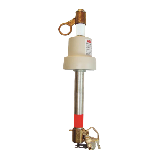
- Page 1 1YSA160045-EN - Rev. 5 Instruction Manual wiAutoLink Wireless Electronic Sectionalizer 15kV, 27kV and 38 kV ...
-
Page 2: Table Of Contents
D.2.2.1. Operating Under Permanent Fault Conditions with Trip two count setting Recloser......27 D.2.2.2. Operating Under Permanent Fault Conditions with Trip three count setting Recloser......28 D.3. Minimum Time Required for Power up the wiAutoLink ..............30 D.4. Minimum Autoreclosing Operating Time required for wiAutoLink operation ......... 30 D.5. -
Page 3: Section A: Safety Notices
Detailed descriptions of procedures, safety principles and service operations are not included on this document. These warnings do not cover all conceivable ways in which service, whether or not recommended by ABB, might be performed or the possible hazardous consequences of each conceivable way, nor could ABB investigate such ways. Anyone using service procedures or tools, whether or not recommended by ABB, must satisfy himself thoroughly that neither personal safety nor equipment safety will be jeopardized by the service method or tools selected. -
Page 4: Section B: Introduction
Section B: Introduction B.1. About this Document This document contains the required information to install medium voltage wiAutoLink Sectionalizer and put it into service. For a correct use of the product, please read it carefully. Like every apparatus we manufacture, wiAutoLink is designed for specific applications. -
Page 5: Section C: Preparing For Use
Make sure that all materials described in the shipping note are included in the supply. If any damage or irregularity is seen in the supplied product after unboxing, notify ABB (directly or through the agent or distributor) as soon as possible within five days of receipt. Please inquire about the terms of warranty from the nearest ABB representative. -
Page 6: Installation
ANSI C37 63: Automatic Sectionalizer. All accident prevention regulations in relative countries. The wiAutoLink is compatible with the Fuses bases model ICX from ABB, Type XS from SYC, Type C from AB Chance and Type L from Cooper. For special installation requirements or other operating conditions, please contact ABB. -
Page 7: Opening Of The Unit
Note: Handle with care without damaging the micro-USB connector. Figure 2. C.4.4. wiAutoLink Configuration Tool C.4.4.1. Installation The WACT tool requires a computer with windows operating system, with USB port and the framework .NET 4.0. The application should be installed following this procedure: Connect the computer to Internet. - Page 8 1YSA160045-EN - Rev. 5 8 / 33 Launch the Installer and follow the indications of the setup shown below. In the event of missing dependencies, the installer process will automatically proceed to the download of missing components. Figure 3. Figure 4. Figure 5.
- Page 9 1YSA160045-EN - Rev. 5 9 / 33 Figure 6. Figure 7. Attach wiAutoLink and be sure that the computer is connected to the internet. Wait for the operating system to download and install the FTDI driver. Open the WACT application:...
- Page 10 Figure 8. C.4.4.2. Simultaneous connection of wiAutoLink units: It is possible to connect simultaneous up to three devices to administrate them through the appropriate TAB. The application creates a section uniquely numbered from 1 to 3, containing the respective data. It is also possible to configure the devices simultaneous using the wizard tool.
- Page 11 Name: Configuration Name. Last: Last change date. Network Pin: code identification of the network to a set of wiAutoLink. Range [0000-9999]. The network pin must be different between near outdoor stations. This Pin is used to identify each wiAutoLink group.
- Page 12 C.4.4.4.2. Scenario_1: Three-Phase standard operation In the case, for example to configure the wiAutoLink for tripping only on permanent faults at 2 counts in a 50 Hz grid of a nominal current of 50A in three phase mode with 30 seconds to reset the fault counts, enable Status LED is enable, and allowed partial trip is disable.
- Page 13 Allow partial trip: yes or not (do not have effect in single phase) C.4.4.4.5. Scenario_4: Single-Phase tripping operation with blinking led Disabled Configure the wiAutoLink as well in chapter 4.4.1.4, but here in this example the, and but here in this example the “enable Status LED” is disabled.
- Page 14 1YSA160045-EN - Rev. 5 14 / 33 Allow partial trip: yes or not (do not have effect in single phase) C.4.4.5. Event Log This event list is stored in the device and displayed in tabular format with the following fields: Counter: Progressive number.
- Page 15 1YSA160045-EN - Rev. 5 15 / 33 C.4.4.6. Statistics Figure 18. This tool is aimed at obtaining a query of the statistics grouped in the following fields: Description: Records description. Unit: measurement unit. Value On the right of the window is seen a graphical representation of the values expressed by the fields “Operating temperatures range in time”.
- Page 16 1YSA160045-EN - Rev. 5 16 / 33 C.4.4.9. File This menu section enables to import or export a file containing the configuration. It can be saved to disk and recall a frequently used configuration in order not to redo it again. Figure 20.
- Page 17 1YSA160045-EN - Rev. 5 17 / 33 Figure 23. C.4.4.9.3. Exit The button closes the application. C.4.4.10. Tools This menu is designed to interact directly with the device. The Global group refers to control all the devices altogether. C.4.4.11. Configuration Wizard The wizard is designed to configure the connected equipment.
- Page 18 1YSA160045-EN - Rev. 5 18 / 33 Figure 25. Using the Load button write a previously saved configuration, just as with the Load setting option from the menu. The device ID can be chosen arbitrary by choosing the advanced button: Figure 26.
- Page 19 1YSA160045-EN - Rev. 5 19 / 33 The wizard can be cancelled any time by pressing the X button on the upper right corner. The Previous Page button is used to go to the previous windows. The writing will only happen when the progress bar is shown. C.4.4.12.
- Page 20 Multiple files can be referred without limit. The following table specifies the different event types that can be recorded by the WiAutoLink (names can be different in reference to the Windows tool revision, here in table below names refers to the WACT 0.0.7):...
- Page 21 1YSA160045-EN - Rev. 5 21 / 33 EventsDeleted Events have been cleared and event counter has been reset FaultDetected Fault non tripping condition Current [0.1 Arms] FaultTrippingCondition Fault tripping condition Current [0.1 Arms] DeadLineCondition Dead line condition ReturnToNormalCondition Device returned to normal condition ResetTimeElapsed Reset time elapsed since last detected fault: counting cancelled...
-
Page 22: Closing Of The Unit
Place the cap, holding the tube with the hand, and tighten it using a 34 mm fork spanner (torque between 8 and 10 Nm) without damaging the O-Ring. Figure 31. C.4.6. wiAutoLink Repositioning Push the interlocking bolt until blocked (it will rotate freely). Do not strike the bolt, nor use any type of tool to reset. Figure 32. Turn the tensioning device support. - Page 23 1YSA160045-EN - Rev. 5 23 / 33 Figure 33. Turn the tripping pin 90°, until the lower contact is firmly blocked. Figure 34. Place the pole in the tube inferior eyelet and position in the cutout-base.
- Page 24 1YSA160045-EN - Rev. 5 24 / 33 Figure 35. Withdraw the pole and place it in the tube’s superior eyelet. Push it until it remains in closing position. Figure 36.
-
Page 25: Commissioning
It is not recommended to open wiAutoLink under charge using a common hookstick, as it could cause an arc that might damage the personnel or the equipment. The... -
Page 26: Section D: Operation Of The Wiautolink
The wiAutoLink is not a fuse tripping device, it will operate to isolate a permanent fault on no load condition. The wiAutoLink fits into a standard fuse cutout and it directly replaces an existing fuse base. -
Page 27: Operating Under Permanent Fault Conditions
The wiAutoLink will pick up, measure zero current and count, reaching its trip count setting. The wiAutoLink will trip on the last open cycle of the recloser, isolating the permanent fault in its branch and allowing the recloser to close prior to going to lockout and maintain power to the unaffected branches. -
Page 28: Operating Under Permanent Fault Conditions With Trip Three Count Setting Recloser
Due to the latest technological improvements recently introduced to reclosers, the time indicated as T2 is the time the recloser takes to open after the fault detected. The wiAutoLink, by means of the spectral analysis in the second harmonic, only needs one cycle to identify a current as a fault current, isolating it from symmetric and asymmetric inrush currents. - Page 29 “Dead line condition” 3. If the upstream recloser or breaker closes and further fault detected, could be considered a permanent fault condition and wiAutoLink process a Fault condition again waiting an opening ”Device returned to normal condition” of the upstream recloser or breaker.
-
Page 30: Minimum Time Required For Power Up The Wiautolink
(wiAutoLink is fully charged). The wiAutoLink is able to detect a fault on the line with a period as small as one cycle. So the recloser can be set to start the tripping command as long as it enables to flow through the sectionalizer one sinusoidal cycle in order to correctly measure the fault using its detection algorithm. -
Page 31: Led Feature For Wiautolink
LED feature for wiAutoLink The wiAutoLink has the added feature of indicating the full operational status of the device once it is fully charged by blinking once the LED in the transformer housing. The blinking LED will happen within 90 seconds of closing the medium voltage line. - Page 32 - Check that the mobile lever and the lower support of the wiAutoLink move easily at the joint. Clean and lubricate the joint surfaces of both pieces.
- Page 33 Power Products Medium Voltage Jose I. Rucci 1051. Valentin Alsina (B1822CJU) Buenos Aires. Argentina. Telephone: +54 11 4229 5500 www.abb.com.ar ©Copyright 2014 ABB, All rights reserved Document Title: wiAutoLink Instruction Book Document No. Date & Rev. Ind. No. of Pages...