Huawei OptiX PTN Series Quick Installation Manual
Packet transport platform
Hide thumbs
Also See for OptiX PTN Series:
- Quick installation manual (45 pages) ,
- Quick installation manual (23 pages)

Related Manuals for Huawei OptiX PTN Series


Summary of Contents for Huawei OptiX PTN Series
- Page 1 OptiX PTN 7900-32 Packet Transport Platform of PTN Series Quick Installation Guide Issue: 16 Date: 2019-10-31 HUAWEI TECHNOLOGIES CO., LTD.
- Page 2 Notice The purchased products, services and features are stipulated by the contract made between Huawei and the customer. All or part of the products, services and features described in this document may not be within the purchase scope or the usage scope. Unless otherwise specified in the contract, all statements, information, and recommendations in this document are provided "AS IS"...
-
Page 3: Installation Flow
Installation Flow Reference information Start Operation Preparing for Installation the Installation Precautions Requirements and Precautions for Operating Boards Required Tools and Equipment OptiX PTN 7900-12 Appearance Installing Boards Installing a Subrack Installing Fan powered box Installing Boards and Components Cable Holes on Installing/Routing Cabinets Cables... -
Page 4: Installation Precautions
Installation Precautions NOTE This document provides guidelines for quick hardware installation. It describes procedures for onsite installation, but does not describe pre-delivery assembly. CAUTION Safety Information Always wear protective gloves when lifting or transporting a cabinet to prevent hand injuries or damage to the cabinet surface. - Page 5 Boards are fragile and vulnerable. When transporting or placing a board, exercise caution and ensure that the board is packed in a dedicated box to protect the board against damage. Boards must be packed with original packaging materials during transportation. If the original packaging materials are lost, contact Huawei technical support personnel.
-
Page 6: Installation Tools
Installation Tools Tools for Installing Cabinets Vacuum cleaner Hammer drill Plumb line Marker cable-pulling pliers 16 drill bit Claw hammer Combination wrench Adjustable wrench Phillips screwdriver Flat-head screwdriver M6-M12 socket wrench Ruler Level Torque wrench Measuring tape powder marker Cold-pressed crimp pliers Network cable tester Multimeter Heat gun... - Page 7 Installation Tools Tools for Installing Cabinets Fiber microscope OTDR meter...
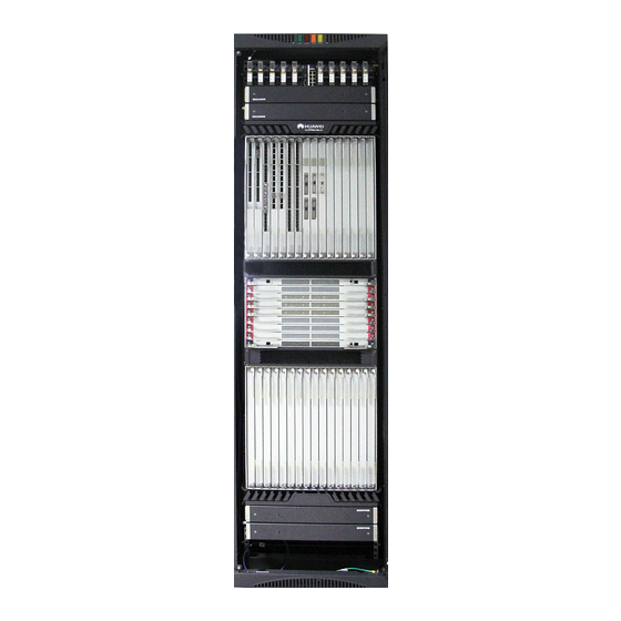
- Page 8 OptiX PTN 7900-32 Appearance Front view of the OptiX PTN 7900-32 NOTE The OptiX PTN 7900-32 consists of the subrack and boards. Cabinet indicators Fan powered box Processing board Cable trough area SCA and XCS board Air deflector area OptiX PTN 7900-32 subrack NOTE Before installing an OptiX PTN 7900-32 cabinet, you must remove the air deflector to prevent it from...
- Page 9 Installing Subrack 1 Installing Subrack NOTE Before installing a subrack into a cabinet, remove the front door and side panels of the cabinet. For details, see the N63B Cabinet Installation Guide. To prevent human injuries or damage to the subrack, at least four people are required during the installation; two to hold the cabinet, one to hold the subrack, the other to install the subrack.
-
Page 10: Installing The Subrack
Installing the Subrack 2 Subrack Architecture NOTE OptiX PTN 7900-32 subrack consists of the service board area, system control board area, switching fabric area, power supply board area, Fan powered box area, and cable routing trough. Cable routing trough Power supply board area Auxiliary interface board area Fan area Processing board area... -
Page 11: Installing Boards
Installing Boards and Components 1 Installing Boards Installing PIU/EFI Boards PIU and EFI boards area of the OptiX PTN 7900-32 PIU and EFI board slots Board Slot Slot46~Slot50 Slot52~Slot56 Slot51 CAUTION Wear an ESD wrist strap or ESD gloves during operations. CAUTION The board is designed for easy installation. - Page 12 1 Installing Boards Installing SCA/XCS Boards CAUTION SCA and XCS board slots Wear an ESD wrist strap or ESD gloves during operations. Board Slot Slot33, Slot41 CAUTION Slot34~Slot40 The board is designed for easy installation. If you feel a blockage when inserting a board into a slot, remove the board and check whether it was inserted correctly or whether it is of the correct type.
- Page 13 1 Installing Boards Installing Service Boards CAUTION CAUTION Service boards or filler panels are inserted differently in the upper and Wear an ESD wrist strap or ESD gloves during operations. lower portions of a cabinet. When installing service boards or filler panels into upper-portion slots, ensure that the ejector levers are on CAUTION the left side of the front panels.
- Page 14 2 Installing Fan powered box NOTE The air flows in the upper and lower portions of a cabinet are in opposite directions, so the Fan powered box assemblies at the top and bottom of the cabinet are installed differently. Four labels are located on the Fan powered box: two on the top surface and two on the bottom.
- Page 15 Installing/Routing Cables 1 Cable Holes on Cabinets (2.2m) Cable holes at the top of the cabinet Cable holes at the bottom of the cabinet Cable/fiber routing When overhead cabling is required: When underfloor cabling is required: Route the power cables out of the cabinet through ...
- Page 16 Installing/Routing Cables 1 Cable Holes on Cabinets (2m) Cable holes at the top of the cabinet Cable holes at the bottom of the cabinet Cable/fiber routing When overhead cabling is required: When underfloor cabling is required: Route the power cables out of the cabinet through ...
- Page 17 2 Installing/Routing Ground and Power Cables Installing Cabinet Ground Cable To the ground bar in the equipment room M8 screw: 120 ±10% kgf· cm To the ground bar in the equipment room Installing Subrack Ground Cable NOTE Ground cable Phillips screwdriver Adjustable wrench The cross-sectional area for the wire of the subrack ground cable is 16mm...
-
Page 18: Selecting Power Cables
2 Installing/Routing Ground and Power Cables Selecting Power Cables Appearance Copper Fittings for Connecting Power Cable Power Ground Cable PIU Boards Copper fitting -48 V power cable PGND power cable Copper plates BGND power cable Left Right Copper fitting Do not cut power cables and crimp power terminals and copper lugs over devices. -
Page 19: Power Cable Connections
2 Installing/Routing Ground and Power Cables Power Cable Connections If no short copper fitting is used, use the 5+5 or 3+3 power NOTE supply mode. The rated input current of each channel is 63 A. OptiX PTN 7900-32 subrack has 10 PIU slots. 63A 63A 63A 63A 63A 63A 63A 63A 63A 63A A and B areas of PIU boards work in hot... -
Page 20: Installing Power Cables
2 Installing/Routing Ground and Power Cables Installing Power Cables CAUTION Do not install or remove power cables while the equipment is powered on. Ensure that the circuit breaker or fuse of the first power cabinet is disconnected prior to removing or installing a power cable to avoid bodily injuries. WARNING •... - Page 21 2 Installing/Routing Ground and Power Cables Routing Ground and Power Cables DANGER Adjustable wrench Phillips screwdriver Do not install or remove power cables while the equipment is powered on. Ensure that the circuit breaker or fuse of the first power cabinet is disconnected prior to removing or installing a power cable to avoid bodily injuries.
- Page 22 3 Installing/Routing NM Cables Overhead cabling Underfloor cabling Network management system Network NOTE managem If 1+1 protection is ent cable configured for the SCA on the equipment, you can use the interface of either the SCA. Network management system Network managem ent cable NOTE...
- Page 23 4 Installing/Routing Housekeeping Alarm Cables One end of the alarm input cable is connected to the The alarm output cable is used to output the alarm signals to the ALMI interface, and the other end of the cable is central alarm monitoring equipment. One end of the alarm output connected to the external device.
- Page 24 5 Installing/Routing Cabinet Indicator Alarm Cables Cabinet alarm indicator cable A cabinet alarm indicator cable connects the LAMP interface on an EFI board to the alarm indicator interface at the top of the cabinet. To the alarm indicator interface at the top of the cabinet ST AT CRIT LAMP...
- Page 25 6 Installing/Routing Network Cables (GE Electrical Module Scenario) CAUTION Among three adjacent interfaces, installing an optical module on an interface between two GE electrical interfaces is not supported. Overhead Cabling Underfloor Cabling Network Cable...
- Page 26 6 Installing/Routing Network Cables (GE Electrical Module Scenario) CAUTION CAUTION A TPA1EG24 or TPA2EG24 equipped with GE A TPA1MPA equipped with GE electrical modules electrical modules must be installed in slot 1, 16, 17 or must be installed in slot 1, 16, 17 or 32 so that 32 so that network cables can be routed on the side of network cables can be routed on the side of the the chassis, without passing through a subrack cable...
- Page 27 7 Installing/Routing E1 Cables CAUTION CAUTION When TPA1MQ1, TPA1MPA, TPA1EG16, TPA1EG24, TPA2EG24 A TPA1MQ1 with E1 interfaces (EG16, EG24 boards equipped with electrical modules) cannot be supported must be installed in installed in the slot 1, 16, 17, or 32 (edge slot). slot 1, 16, 17, or 32.
- Page 28 Installing/Routing Fibers 1 Open-End Corrugated Pipe Introduction NOTE Do not use an open-end corrugated pipe to hold excessive fibers. It is recommended that an open- end corrugated pipe that has a diameter of 32 mm accommodate 60 fibers at most, each with a diameter of 2 mm.
- Page 29 3 Installing/Routing External Fibers CAUTION If the tab of an optical module is loose, remove and re-install the optical module to prevent unstable network. Overhead Cabling Underfloor Cabling NOTE Routing fibers into fiber trough. It is recommended that the fibers connecting the SFUs on both sides are routed through their own fiber troughs.
- Page 30 3 Installing/Routing External Fibers Prepare for Fiber Routing – Remove the Front Door of the Cabinet Use a screwdriver to loosen the ground screw at Hold and pull down the lock rod on the upper part the bottom of the cabinet door and disconnect the of the cabinet door to separate the rotating shaft cabinet door from the ground cable.
- Page 31 3 Installing/Routing External Fibers Prepare for Fiber Routing – Remove the Side Panel and Rat Guards from the Cabinet NOTE If the side panel of the cabinet has been removed, skip this step. Use an M6 socket wrench to remove the ground nut Remove the two screws marked in the figure and from the side panel.
- Page 32 3 Installing/Routing External Fibers Route and Bind Optical Fibers Bind the optical fibers on the side of the cabinet. Insert optical fibers into the board, arrange the fiber Arrange the optical fibers that are routed through the jumpers, and bind them. Place the optical fibers on cable troughs of the chassis, and then place them into the board into cable troughs from the middle to both the cabling channel between the fiber fixture and the...
- Page 33 3 Installing/Routing External Fibers Complete Fiber Routing – Install the Side Panel and Rat Guards Insert the side panel according to the figure. Do Install screws in four positions marked in the not clamp optical fibers. figure. Install the ground cable. (The ground points on Tailor rat guards from the inside based on the the side panels are symmetrical).
- Page 34 3 Installing/Routing External Fibers Complete Fiber Routing – Install the Front Door of the Cabinet Alignment hole of the rotating shaft at the bottom Alignment hole of the rotating shaft at the top Stand the cabinet door, insert the lower rotating shaft into the alignment hole of the cabinet, pull down the upper lever of the cabinet door, and insert the upper rotating shaft into the alignment...
-
Page 35: Post-Installation Checklist
Performing the Post-installation Check 1 Post-installation Checklist When the installation is complete, double check that these items have been properly performed. What to Check For Method The cabinets are positioned in the places defined by the site-specific engineering design. Visual inspection The subrack and other components are properly installed and are free of damage or Visual inspection loose parts. - Page 36 Equipment Inspection Before Power-On Provisioning Power for the Equipment Power off the first power cabinet. Switch the PIU to ON, and use a multimeter to all of the measure resistance between any two of NEG(-), RTN(+), and PGND (PGND). Switch the PIU to OFF, and use a multimeter to measure all of the resistance between any two of NEG(-), RTN(+), and PGND (PGND).
- Page 37 Checking Optical Power The following table describes comparison between the transmit optical power of 50 Gbps optical modules and damaged optical power threshold at the receive end: Optical Maximum Minimum Average Damaged Optical Description Module Type Average Transmit Transmit Optical Power Threshold Optical Power Power...
- Page 38 Provisioning Optical Paths Station B Station A East West Fiber patch cord Optical power meter Measure the OUT port power of the FIU board at the transmit end. Record this reading as a. Measure the fiber output power on the ODF side at the transmit end. Record this reading as b. Measure the fiber input power on the ODF side at the receive end.
-
Page 39: Engineering Labels
Engineering Labels 1 Affixing Labels NOTE Affix a label to a cable/fiber 2 cm away from its connectors. Affixing a Label to a Power Cable Identification plate Attach the identification plate on the right side of the cable B03 — -48V2 when the cable is routed vertically. - Page 40 2 Standard Engineering Labels Name Content Example Note MN(BC): BC is written right under -48V2 B03 -48V2 MN. On the loaded cabinet side, MN identifies the row and column number of the power distribution facilities (such as the power control cabinet MN(BC) - -48V1 and power distribution box).
- Page 41 Appendix 1 CFP Optical Module Installing the CFP Optical Module Push the CFP optical module in the Tighten the screws after inserting the CFP slot with proper force. optical module into the slot. Optical Power Commissioning Before optical signals are input into an optical module, commission the input optical power of the optical interface (RXn) to be within the optimal value range: (Receiver sensitivity + 3) dBm to (Overload point –...
- Page 42 HUAWEI TECHNOLOGIES CO., LTD. Huawei Industrial Base Bantian Longgang Shenzhen 518129 People’s Republic of China www.huawei.com...