
Related Manuals for ABB CPS6000


Summary of Contents for ABB CPS6000
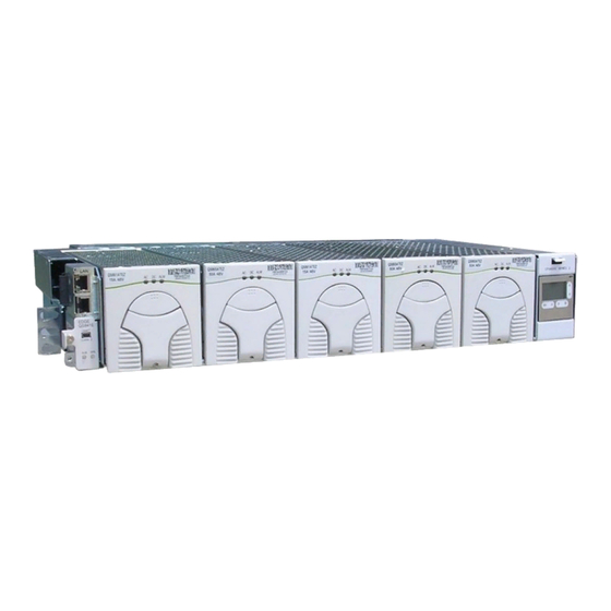
- Page 1 PRODUCT MANUAL CPS6000 -48V Indoor/Outdoor Power Shelf Product Manual Select Code 167-102-105 Ordering code 108992120 Issue 21 January 2008 Page 1 © Copyright 2021 ABB. All rights reserved.
- Page 2 QS865A 1:1E Notice: The information, specifications, and procedures in this manual are subject to change without notice. ABB Power assumes no responsibility for any errors that may appear in this document. Page 2 © Copyright 2021 ABB. All rights reserved.
-
Page 3: Table Of Contents
Precautions ..............................34 Special Installation Notes .......................... 34 5 Installation ............................37 CPS6000 Installation ..........................37 Installing the CPS6000 Shelf ........................38 Install the CPS6000 Shelf .......................... 40 Controller ..............................41 QS845A Supplementary Shelf Board ....................... 43 Thermal Compensation Connections ...................... 45 Office Alarms ............................... - Page 4 Auxiliary Alarms ............................80 Additional Bulk Output Module Connections ..................81 7A QS840A System Controller ......................83 Overview ............................... 83 CPS6000 Controller Minimum Configuration..................89 User Interface and Display......................... 89 Minimum Configuration ..........................89 7B QS841A System Controller ......................99 Overview ...............................
- Page 5 Boost Mode ..............................179 Appendix C: Alarms and Relays ......................181 Alarm Relays ..............................181 Alarms ................................181 Appendix D: EasyView for Windows® for the CPS6000 Controller ............ 189 Overview ............................... 189 Loading the EasyView Application ......................189 Making the Connection ..........................189 Configuring a Site ............................
- Page 6 This page intentionally left blank Page 6 © Copyright 2021 ABB. All rights reserved.
-
Page 7: Introduction
Figure 1-1: CPS6000 System with Distribution Module The CPS6000 currently supports -48V primary loads up to 8.2kW of N+1 redundant power in a single 19-inch shelf, and up to 10.9kW of N+1 redundant power in a 23-inch shelf with a Bulk Output Module and 50A rectifiers. -
Page 8: Customer Service Contacts
For other customers worldwide the 800 number may be accessed after first dialing the ABB Direct country code for the country where the call is originating, or you may contact your local field support center or your sales representative to discuss your specific needs. -
Page 9: Product Description
LVLD in the Distribution Module. CPS6000 disconnects these loads at a set threshold during a battery discharge. This reduces drain on the batteries and extends reserve time available for critical loads. -
Page 10: Block Diagrams
Block Diagrams 2-1a and 2-1b are basic block diagrams of the CPS6000 System in a single shelf with a Distribution Module. Figure 2-2 shows the Bulk Output Module in place of the Distribution Module. Figure 2-1a: CPS6000 System with Distribution Module Page 10 ©... - Page 11 Figure 2-1b: CPS6000 System with Distribution Module Page 11 © Copyright 2021 ABB. All rights reserved.
-
Page 12: Shelf Design
Figure 2-2: CPS6000 System with Bulk Output Module Shelf Design Features • The shelf is available in 19-inch (phase 2) and 23-inch standard widths and has the following features: • Accepts plug-in rectifier, ringer and Distribution Modules. • 19-inch shelves provide 4 Power Slots •... -
Page 13: Configurations
The 23-Inch Shelf provides five Power Slots. Power Slots support Rectifiers, Ringer Chassis, and Distribution Modules. Figure 2-3 shows the show the locations of the CPS6000 components in the19-inch and 23-inch shelves with the Single-Slot Distribution Module. 19 - Inch Shelf... -
Page 14: Battery Reserve System
Figure 2-4: Distribution and Power Module Configurations Battery Reserve System Introduction A battery reserve system is a key component for a reliable power system. The CPS6000 provides a primary voltage of -48V that drives load equipment. At the same time, it provides float and recharge capability for the battery reserve system. -
Page 15: Specifications
Underwriters Laboratories (UL) Listed per Subject Letter 1801: Power Distribution Center Communications Equipment, and cUL Certified (CSA 22.2 950): Safety of Safety Agency Approval Information Technology Equipment VDE licensed to VDE0805/EN60950 Table 2-A: CPS6000 System Specifications Page 15 © Copyright 2021 ABB. All rights reserved. - Page 16 Table 2-A: CPS6000 System Specifications (continued) Installation Category CPS6000 is suitable for connection to ac utility systems where the expected level of lightning surges complies with ANSI C62.41 Category B or IEC 60664-1 Overvoltage Category II. A service entrance surge protector is required in applications where the installation categories can not be classified as being compliant to either ANSI C62.41 Category B or IEC 60664-1 Overvoltage Category...
- Page 17 177W (604 BTU) per QS862A at full load and Heat Dissipation 120 V operation; 132W (450 BTU) per QS861A rectifier at full load and 120 V operation; Table 2-C: CPS6000 Shelf Specifications Page 17 © Copyright 2021 ABB. All rights reserved.
- Page 18 Power Factor > 0.98 for loads > 50% of full load Table 2-C: CPS6000 Shelf Specifications (continued) Note: Maximum current is based on Bulk Output Module and 50A QS865A rectifier. System capacity will decrease with lower rated rectifiers Power Slots Available for Rectifiers or Ringer Chassis...
- Page 19 212W (724 BTU) at 200 to 240 V operation Power Factor >0.98 for loads > 50% full load Selective High-Voltage Shutdown Above 58 V Backup High-Voltage Shutdown Above 60 V for 1 millisecond Table 2-G: QS862A Rectifier Specifications. Page 19 © Copyright 2021 ABB. All rights reserved.
- Page 20 267W (911 BTU) at 240 V operation Power Factor >0.98 for loads > 50% full load Selective High-Voltage Shutdown Above 58 V Backup High-Voltage Shutdown Above 60 V for 1 millisecond Table 2-I: QS865A Rectifier Specifications Page 20 © Copyright 2021 ABB. All rights reserved.
- Page 21 PC with RS-232 port. 841 also has 10/100 Baset-T network ability Alarm Contact Ratings 60 V , 0.5A, Form-C Operating Temperature -40 to +75 °C Table 2-K: QS840A and QS841A Control Unit Specifications Page 21 © Copyright 2021 ABB. All rights reserved.
- Page 22 Input power through QS840A or QS841A Plant Parameter Setting None, communicates with shelf components QS840A/ QS841A Alarm Contact Ratings None Operating Temperature -40 to +75 °C Table 2-L: QS845A Supplementary Board Specifications Page 22 © Copyright 2021 ABB. All rights reserved.
-
Page 23: Engineering And Ordering
Typically, the number of spare rectifiers required for a redundant system is the larger of one spare rectifier or 200% of the rated load. Page 23 © Copyright 2021 ABB. All rights reserved. - Page 24 In this high line ac example using QS862A 1635W (200-240 Vac) constant power rectifiers, three rectifiers (3761/1635 = 2.3) are needed to support the load and recharge the batteries within the requisite time. Page 24 © Copyright 2021 ABB. All rights reserved.
-
Page 25: Ordering Information
Ordering Information Ordering Guide An ordering guide may be downloaded from the ABB Power web site. This guide will augment the information found here. Note: Ordering information here is presented only from the viewpoint of miscellaneous item ordering and may not be complete. Complete System ordering should done using the ordering guide only. - Page 26 No more than 80A may be carried through the 10 fuse positions, or 40A through each half section. 15A and lower rated fuses may be used in any combination and position, as long as they do not violate the previous 80A/40A rule. Page 26 © Copyright 2021 ABB. All rights reserved.
- Page 27 QS840A/QS841A controller on the primary shelf. Rectifiers The constant-power rectifiers each occupy a single slot in the CPS6000 shelf. If a full complement of rectifiers is not required, a rectifier slot filler may be to cover empty rectifier slots. The slot filler is not necessary from an earthquake standpoint.
- Page 28 AC Power Cables An ac power cable must be ordered. A standard ac cable set will not fit in the CPS6000 shelf. Verify that the sum of the input currents for all the rectifiers served by an ac circuit breaker does not exceed 80% of the breaker’s rating.
- Page 29 VT-probe and its associated cables must be ordered. Refer to Section 5 for details on their interconnection, and Section 9 for more information on VT-Probes and voltage monitoring. Page 29 © Copyright 2021 ABB. All rights reserved.
- Page 30 The Remote Distribution Monitor Module allows the CPS6000 system controller to monitor for open circuit breakers and fuses, monitor current through a battery shunt, and monitor/control low-voltage disconnect contactors at an external distribution panel that is bulk-fed from the CPS6000 system. See Section 11 for more details.
-
Page 31: Safety
• The CE Mark demonstrates compliance with the European Union Council Directives for Low Voltage and EMC. • The CPS6000 platform is Underwriters Laboratories (UL) Listed per Subject Letter 1801, DC Power Distribution Centers for Telecommunications Equipment. • CPS6000 shelves equipped with QS820A ringers (in development) have hazardous secondary voltages on the secondary bus output connectors. - Page 32 • CPS6000 outputs are not connected to earth. Earthing of rectifier outputs may be performed externally to the shelf at a “ground window” or “mesh ground”. Connection of Ringer tip outputs to CPS6000 Battery or Ground is optional via Ringer Chassis jumper or external connection.
-
Page 33: Warning Statements And Safety Symbols
This symbol is used to identify the need for safety glasses and may sometimes be accompanied by some type of statement, for example: “Fuses can cause arcing and sparks. Risk of eye injury. Always wear safety glasses.” Page 33 © Copyright 2021 ABB. All rights reserved. -
Page 34: Precautions
( Warning : For continued protection against fire replace with same type and rating of fuse ) Das System ist ein Gerät der Schutzklasse I / Überspannungs Kategorie II ( Power Supply is a Class I equipment / overvlotage category II ) Page 34 © Copyright 2021 ABB. All rights reserved. - Page 35 Vea tabla 2-A • Temperatura máxima de operación (Maximum Operation Temperature): 75°C (167°F) • Sin cabina contra incendios, suelo no combustible (No fire enclosure, non-combustible floor) • Evaluado en EN60950 (Evaluated to EN60950) Page 35 © Copyright 2021 ABB. All rights reserved.
- Page 36 This page intentionally left blank Page 36 © Copyright 2021 ABB. All rights reserved.
-
Page 37: Installation
5 Installation CPS6000 Installation Purpose CPS6000 Shelf Installation guide for generic installations. Additional requirements are needed for application specific installations. Refer to Appendix F for spacing requirements. Audience Field application personnel. Precautions Observe ESD protection while installing circuit packs Safety Always consider personal safety. -
Page 38: Installing The Cps6000 Shelf
There are two distribution options for the CPS6000, a Single-Slot Distribution Module and a Bulk Output Module. Only one distribution box can be used in a CPS6000 shelf. This hardware assembly is field installable, however in most cases the factory will have already installed the distribution module when it is required. - Page 39 #4 Screw (901376756) 3/8” Bolt (801085119) Hand Tight 3/8” Lock Washer (802286773) ( Approximately 5 in - lb ) 3/8” Flat Washer (814251898) Torque : 240 in - lb Figure 5-3: Distribution Module Page 39 © Copyright 2021 ABB. All rights reserved.
-
Page 40: Install The Cps6000 Shelf
Thermal Probe Connection Leave a sufficient service loop on these cables. Install the CPS6000 Shelf Follow the steps in the table below to mount the CPS6000 shelf into a 19-inch or 23-inch frame. Step Action Locate the 2 mounting brackets, one on each side of the CPS shelf; align the holes in the shelf-mounting bracket with the holes in the mounting frame. -
Page 41: Controller
Insert the tab on the bottom of the faceplate into the slot on the bottom of the controller housing. Push the display faceplate into the shelf until the latch on the top of the controller housing catches. ESD Strap Connector ESD Strap Connector Slide the controller into the shelf Page 41 © Copyright 2021 ABB. All rights reserved. - Page 42 Push the faceplate into the shelf until the latch catches on the top Tab on the bottom of the faceplate inserted into slot in the shelf Page 42 © Copyright 2021 ABB. All rights reserved.
-
Page 43: Qs845A Supplementary Shelf Board
QS845A Supplementary Shelf Board Multi-Shelf Installations The QS845A allows up to four CPS6000 shelves to be paralleled. It can be used either with the QS840A or the QS841A controller. This board is installed in the controller position on supplemental CPS6000 shelves and enables the subsequent shelf equipment to communicate with the controller on the initial shelf. - Page 44 NEXT SHELF connector, to the next applicable shelf connector as shown. QS845A on Shelf 4 QS845A on Shelf 3 QS845A on Shelf 2 Controller in Primary Shelf J2 SHELF/SHELF Connector Bend back insulation cover Figure 5-7: Inter-Shelf Connections Page 44 © Copyright 2021 ABB. All rights reserved.
-
Page 45: Thermal Compensation Connections
Attach probe case to each VT-Probe making sure the case pin inserts into the hole on the probe. Close the case and verify the case is securely latched. See Figure 5-9. Page 45 © Copyright 2021 ABB. All rights reserved. - Page 46 Wires to straddle case as shown Place QS873A VT PROBE in case make sure case in inserts into hole in board Figure 5-9a: Connecting Battery Monitor Voltage Wire to Thermal Probe Cable Page 46 © Copyright 2021 ABB. All rights reserved.
- Page 47 V- Power QS873A Cable VT Probe Mounting Hardware Mount or top of Do Not mount beneath power lg (as shown) power lug Figure 5-9c: Connecting Thermal Probe Cable to the battery Page 47 © Copyright 2021 ABB. All rights reserved.
- Page 48 (figure 5-8). If battery voltage monitoring is used, trim and insulted the trimmed end of this wire. 108987611 QS873A Thermal probe Figure 5-10: VT-Probe/Battery Voltage Monitor Connections to Controller Page 48 © Copyright 2021 ABB. All rights reserved.
-
Page 49: Office Alarms
Connect the Office Alarm Cable to J1 on the QS840A Controller. Figure 5-11: J1 Office Alarm Connector Refer to Appendix E for an adapter cable that uses the CPS4000 alarm color scheme if required. Page 49 © Copyright 2021 ABB. All rights reserved. -
Page 50: Controller Connections
AC Connections AC Connections to Shelf Review the ac connection on the installed shelf. Refer to Tables 3-B and 3-C for detailed CPS6000 rectifier ac input requirements. Caution: Ensure ac power is OFF and use appropriate lock-out tag-out procedures before continuing with ac connections. - Page 51 Terminate the supply end of the cable with an appropriate plug (plug not provided). AC Input Connectors Figure 5-12a: Dual AC Input Connections AC Input Connectors AC Input Cable Figure 5-12b: Single cord AC Input Connections Page 51 © Copyright 2021 ABB. All rights reserved.
- Page 52 Knockout for 3/4 - Inch Conduit or type “SO” cord. One AC Input foe each Group of Rectifiers AC Input Rectifiers 1, 3 , and 5 Rectifiers 2 and 4 Figure 5-12d: Rear AC Input Connections Page 52 © Copyright 2021 ABB. All rights reserved.
- Page 53 CAUTION: Disconnect all AC branch circuits prior to making AC connections to the CPS6000 System. Ensure ac power is OFF to the CPS6000 system before continuing with ac When connecting to utility source, ensure all local and national wiring rules are being complied with.
-
Page 54: Ground Conductor Installation
Use bottom holes to route cable up as shown or use top holes to route able down 2 position For C.O. Ground Distribution Module Right Side View Figure 5-14a: C.O. Ground Conductor Connection Page 54 © Copyright 2021 ABB. All rights reserved. -
Page 55: Rectifier Installation
Rectifier Installation Install the Rectifier This procedure is used to install the rectifier in the CPS6000 shelf. Figure 5-15 is a 23-inch shelf with 4 rectifier positions and a Single-Slot Distribution Module. Note: All rectifier ac and dc connections are made when rectifiers are seated in the shelf. Rectifiers will power up when ac is applied to the shelf. -
Page 56: Ringer Installation
Install the Ringer Chassis and Ringer Modules This procedure is used to install ringer chassis’s and ringer modules in the CPS6000 shelf. Figure 5-16 shows a shelf, Ringer chassis and a Distribution Module. Up to two Ringer Chassis’s may be installed per shelf, one in each of the two right-most power slots to the left of the Distribution Section. - Page 57 Note: The Ringer modules install facing opposite directions. See figure 5-17. Repeat until all primary and spare ringer modules are installed. Page 57 © Copyright 2021 ABB. All rights reserved.
- Page 58 Connect Ringer loads using Molex 39-01-4031 connector, Socket Terminal to the HDR13 plug located inside the Ringer Chassis at the bottom-front. See Figure 5- 18. Route ringer load cables through upper or lower notches in Ringer chassis and distribution module chassis. See Figure 5-18. Page 58 © Copyright 2021 ABB. All rights reserved.
-
Page 59: Battery Strings Installation
Warning: If a battery disconnect switch is being used, mount the switch before proceeding and make sure it is in the OFF/OPEN position prior to making any connections. Connect Battery Strings This procedure is used to connect up to four battery strings to the CPS6000. Step Action If battery circuit breakers are required, remove the straps installed by the factory and install the bullet-style circuit breakers into the bottom two positions in the Distribution Module. - Page 60 Battery Circuit Return Cables Breaker Position String 4 String 4 String 3 String 3 String 2 String 2 String 1 String 1 Figure 5-19b: Battery String Connections – Single-Slot, No GMT Fuses Page 60 © Copyright 2021 ABB. All rights reserved.
- Page 61 Single - Slot Distribution Module Front View with Door Open Battery Circuit Braker Positions String 2 Battery Power (V-) String 2 String 1 String 1 Figure 5-19d: Battery String Connections – Single-Slot, 10 GMT Fuses Page 61 © Copyright 2021 ABB. All rights reserved.
-
Page 62: Load Connections
Insert Load breakers in the top two positions in the Distribution Module. Terminate the load cables on the load buss with M6 nuts and torque to 65 in-lb (7.3Nm). See Appropriate Figures 5-20a, through 5-20c for Distribution Module connections. Page 62 © Copyright 2021 ABB. All rights reserved. - Page 63 Battery Power Load Cables Vout 2 Vout 2 Vout 1 Vout 1 C.O Ground Position Cables route behind GMT fuse Board Figure 5-20b: Front Load Connections – Single-Slot, 5 GMT Fuses Page 63 © Copyright 2021 ABB. All rights reserved.
- Page 64 Circuit Braker 2 Circuit Braker 1 Circuit Braker Load Returns (RTN) 4– Position Bus Bar for Battery and Load Returns (RTN) Figure 5-20c: Front Load Connections – Single-Slot, 10 GMT Fuses; Double-Slot Page 64 © Copyright 2021 ABB. All rights reserved.
- Page 65 Terminal Blocks 5 Primary GMT Fuse Position Load Load Return Power Terminal Terminal Half– Section Half– Section GMT Fuse Positions GMT Fuse Terminal Blocks Figure 5-21: GMT Fuse Connections, Single-Slot Distribution Module Page 65 © Copyright 2021 ABB. All rights reserved.
- Page 66 16 GMT Fuse Positions Load Power Terminal Blocks Load Return Terminal Blocks Load Load Power Return Terminal Terminal GMT Fuse Positions GMT Fuse Terminal Blocks Figure 5-22: GMT Fuse Connections, Double-Slot Distribution Module Page 66 © Copyright 2021 ABB. All rights reserved.
-
Page 67: Circuit Breaker And Fuse Installation
Retention Bracket Figure 5-23: Circuit Breaker Retention Bracket Alarm Contact Receptacle Alarm Contacts Indicator GMT Fuse Battery Circuit Breaker (Double– Slot Distribution Module Only) Figure 5-24: Circuit Breaker and Fuse Installation Page 67 © Copyright 2021 ABB. All rights reserved. -
Page 68: Terminate Load Connections - Direct To Bus Connections
Front Post of the lug cover into the mounting hole and snap the tab on the back of lug cover into place Figure 5-25: Direct Connection to V+ (shown) / V- Output Bus Page 68 © Copyright 2021 ABB. All rights reserved. -
Page 69: Load Connections - Bulk Output
Figure 5-26a: Front Bulk Output Load Connections – up to 2Awg -48V Connections (1 ga) RNT Connections (1 ga) Bulk Output Distribution Module Figure 5-26b: Large Cable (1Awg) Bulk Output Load Connections Page 69 © Copyright 2021 ABB. All rights reserved. -
Page 70: Battery And Load Connections - External Dc Distribution Panel
Alarm Jumpers Return Connections Output Connections Circuit Breaker / Battery Switch Positions 4 battery 18 Output (Load ) positions Positions Figure 5-27: Distribution Factory Configuration Page 70 © Copyright 2021 ABB. All rights reserved. - Page 71 Using a voltmeter, verify polarity of the battery connection between the RTN and battery input bus. Leave the switch in the OFF position until the unit is ready to be energized. Remove four circuit breaker terminal posts Figure 5-28: Remove Circuit Breaker Terminal Posts Page 71 © Copyright 2021 ABB. All rights reserved.
- Page 72 Figure 5-29: Install 4-String Battery Busbar Install alarm jumper Remover alarm jumper into this position from this position Alarm Jumper Figure 5-30: Relocate Alarm Jumper Page 72 © Copyright 2021 ABB. All rights reserved.
- Page 73 FLEX Wire Ga Ordering Code (class B) (class I) 405356171 14 - 10 14 - 10 406338665 405348178 405348228 406338400 405348236 405347576 406021725 405348202 405348251 405347683 405347923 407817568 407890763 407817550 407890748 407817576 Page 73 © Copyright 2021 ABB. All rights reserved.
-
Page 74: Initial Start-Up
If using battery disconnect switches place them in their ON/CLOSED positions prior to applying ac power. Turn on the ac service circuit breakers to apply power to the CPS6000 power system. Verify that All LEDs on all components including rectifiers, controllers, LVD boards, and remote voltage monitor modules are green. - Page 75 1.0 Default Web Pages version 1.0 Custom Web Pages not found Ethernet Address 00-60-1D-00-5C-07 IP Address not configured Subnet Mask not configured Default Gateway not configured Host Name not configured For assistance type help Page 75 © Copyright 2021 ABB. All rights reserved.
- Page 76 After approximately one minute, observe the LEDs on the J3 net work connector: Green - STATUS LED: ON Yellow - Link / Active LED: ON The QS841A should be communicating over the network. Page 76 © Copyright 2021 ABB. All rights reserved.
-
Page 77: Ac, Alarm, And Control Cable Reference Information
AC Utility Connection Note: Each ac connection to the CPS6000 shelf is to be provided with circuit breaker protection at maximum 40A for a 23-inch shelf with dual ac feed and low-line (120V) input. For high-line (200-240V) input, a 40A circuit breaker is adequate. - Page 78 The signals and pin assignments for this interface are shown in the following table: Signal Description RS-485 + RS485 GP communication bus RS-485 - RS485 GP communication bus SIG_RTN Protected signal return for RS485 and 1-wire 1-Wire 1-wire communication signal Protected +5V Power Page 78 © Copyright 2021 ABB. All rights reserved.
- Page 79 The signals and pin assignments for this interface follow industry standard and are shown in the following table: Signal Description Tranceive Data+ Tranceive Data- Receive Data+ Not connected Not connected Receive Data- Not connected Not connected Page 79 © Copyright 2021 ABB. All rights reserved.
-
Page 80: Auxiliary Alarms
Mating connector information for this 4-pin connector is as follows: Housing: Amp part number 1445022-4 Contact (on a strip): Amp part number 794606-2 Contact (loose piece): Amp part number 794610-2 Page 80 © Copyright 2021 ABB. All rights reserved. -
Page 81: Additional Bulk Output Module Connections
Pins 1 and 2 (Vsense- and Vsense+) on J2 are wired to monitor system voltage internal to the Bulk Out- put Module. To monitor system voltage externally, unplug the mating connector from J2 and connect Vsense- and Vsense+ to the external source to be monitored. Page 81 © Copyright 2021 ABB. All rights reserved. - Page 82 This page intentionally left blank Page 82 © Copyright 2021 ABB. All rights reserved.
-
Page 83: Qs840A System Controller
Otherwise, the left and right arrow keys are used to navigate the menus and the up and down arrow keys are used to change values when configuring the system. A black box highlighting a menu item indicates that the item has sub-menus. Page 83 © Copyright 2021 ABB. All rights reserved. - Page 84 An isolated RS-232 connector (J3) is provided for local access or for connection to an external modem. The software interface is compatible with ABB Power EasyView for Windows GUI software for PCs. Software support is also provided for use with ABB Power Galaxy Manager for web-based remote access and monitoring.
- Page 85 Status Menu Figure 7-3a: Software Menu Map Page 85 © Copyright 2021 ABB. All rights reserved.
- Page 86 Control / Operation History Menus Figure 7-3b: Control / Operations and History Menus Page 86 © Copyright 2021 ABB. All rights reserved.
- Page 87 Configuration Menu Figure 7-3c: Configuration Menu (part 1) Page 87 © Copyright 2021 ABB. All rights reserved.
- Page 88 Configuration Menu (continued) Figure 7-3d: Configuration Menu (part 2) Page 88 © Copyright 2021 ABB. All rights reserved.
-
Page 89: Cps6000 Controller Minimum Configuration
CPS6000 Controller Minimum Configuration General Information QS840A is the nerve center of the CPS6000 Battery Plant. The controller has six alarm relays; Two are pre-assigned as power major and power minor alarms. The four remaining relays are available as user-definable alarms to external devices. - Page 90 Press the down arrow key until Configuration is highlighted, press the Display Menu key and the follow- ing selections are available; Float settings, Shunt rating, Rectifier Redundancy, Batteries, Contactors, Boost, System Settings, and Communication Ports. Page 90 © Copyright 2021 ABB. All rights reserved.
- Page 91 Rectifiers: Total installed capacity of the system, total output current of all rectifiers, and the individual rectifier currents by rectifier number (Gnn). Batteries: The following battery management information is available under Status: Page 91 © Copyright 2021 ABB. All rights reserved.
- Page 92 Imminent system shutdown alarm (LVBD) Local Write Whether or not the system can be configured through the local port. Modem Write Whether or not the system can be configured through the modem port. Page 92 © Copyright 2021 ABB. All rights reserved.
- Page 93 Chronological view of the last 10 battery on discharge (BD) events since the last time the BD History history log was cleared. Chronological view of the last 10 times the system entered boost mode since the last time the Boost History history log was cleared. Page 93 © Copyright 2021 ABB. All rights reserved.
- Page 94 Very Low Voltage Major voltage. Shunt Monitors: Versions of the CPS6000 are equipped with a battery or load shunt. For those shelves that do not have shunts these settings are not used. The QS840A utilizes RS485 serial communication to external distribution monitoring and control boards for shunt measurements and contactor control.
- Page 95 *See Appendix B for detailed descriptions of the Thermal Compensation and Battery Test features and parameters. Contactor Interfaces: Various CPS6000 shelves and systems utilize contactors. The QS840A can be configured to monitor external control boards that can be assigned to LVD contactor control by appropriately configuring a unique board ID to a specific contactor function.
- Page 96 LVBD. The alarm is issued based on the lower disconnect threshold of the multiple contactors. This feature is factory Disabled. Ringers: Ringer modules are an option for the CPS6000. The QS840A has the ability to manage two ringer chassis. Configuration for the ringer settings are shown below.
- Page 97 Set port Flow Control to none or SW (software). The factory default setting is none. Set the number of rings to be detected by the modem before it answers (Rings to Answer). Can be set from 1 to 9. The factory default setting is 1. Page 97 © Copyright 2021 ABB. All rights reserved.
- Page 98 This page intentionally left blank Page 98 © Copyright 2021 ABB. All rights reserved.
-
Page 99: Qs841A System Controller
Otherwise, the left and right arrow keys are used to navigate the menus and the up and down arrow keys are used to change values when configuring the system. A black box highlighting a menu item indicates that the item has sub-menus. Page 99 © Copyright 2021 ABB. All rights reserved. - Page 100 EBW Network Interface Card known as the Gateway to provide a second Ethernet port. The Ethernet ports are compatible with ABB Power Galaxy Manager used for web-based remote access and network management. This serial port can also be used to provide local access or for a connection to an external modem in non-NX400 systems.
- Page 101 9. System Date 10. System Time Format 11. System Time 12. Automatic Daylight Savings Feature 13. Display Contrast 14. Temperature Display Units 15. Alarm Test Feature 16. Alarm Test Relay Duration and Relay Page 101 © Copyright 2021 ABB. All rights reserved.
- Page 102 “No Active Alarms” or “No Active Warnings” will be displayed when they are no alarms or warnings detected by the controller. NOTE: Controller may have menu options than those mentioned here due to improvements. Page 102 © Copyright 2021 ABB. All rights reserved.
- Page 103 Status Menu Figure 7-3: Status Menu Page 103 © Copyright 2021 ABB. All rights reserved.
- Page 104 Control / Operation History Menus Figure 7-4: Control / Operations and History Menus Page 104 © Copyright 2021 ABB. All rights reserved.
- Page 105 Configuration Menu Figure 7-5: Configuration Menu (part 1) Page 105 © Copyright 2021 ABB. All rights reserved.
- Page 106 Configuration Menu (continued) Figure 7-6: Configuration Menu (part 2) Page 106 © Copyright 2021 ABB. All rights reserved.
-
Page 107: Status
High Batt Temp Highest temperature being measured by the thermal probes Reserve Low Low battery reserve time alarm High Ambient Temp High ambient temperature alarm Low Ambient Temp Low ambient temperature Page 107 © Copyright 2021 ABB. All rights reserved. - Page 108 Host. The format for the Subnet Mask field is a 32-bit numeric address written as four numbers separated by periods (ddd.ddd.ddd.ddd). Each number digit, d, can be zero to 255. Page 108 © Copyright 2021 ABB. All rights reserved.
-
Page 109: Control/Operations
Clear Events Battery, Reserve Time Low, Battery Voltage Imbalance Clears alarms related to the removal of a system component such as a rectifier, thermal probe, Uninstall Equipment or voltage monitoring module. Page 109 © Copyright 2021 ABB. All rights reserved. - Page 110 Chronological view of the last 16 times the system entered boost mode since the last time the Boost History history log was cleared. Chronological view of the last 256 rectifier alarms and events that have occurred since the last Rectifier History time the history log was cleared. Page 110 © Copyright 2021 ABB. All rights reserved.
-
Page 111: Configuration
Alarm indicates an imminent system shutdown due to discharging batteries or low output Very Low Voltage Major voltage. The alarm threshold can be set from -40V to -51V in 0.1V increments. The factory default setting is -46.0V. Page 111 © Copyright 2021 ABB. All rights reserved. - Page 112 The type of batteries used in the system and can be set for the following battery types: SE48S63 (Li-LMP) • SE48S80 (Li-LMP) • NSB110FT (VRLA) • NSB170FT (VRLA) • Battery Type NSB60FT (VRLA) • IR30EC (VRLA) • IR40EC (VRLA) • 12A100FT (VRLA) • 12A150FT (VRLA) • Page 112 © Copyright 2021 ABB. All rights reserved.
- Page 113 1.7V. This alarm is only generated after batteries have been sitting on float for a minimum of 24hours. *See Appendix A for detailed descriptions of the Thermal Compensation and Battery Test features and parameters. Page 113 © Copyright 2021 ABB. All rights reserved.
- Page 114 LVDs. In this case the elapsed time configured is the time from once the reconnect voltage threshold has been reached. Disconnects are not used in the CPS6000-L. Thus, the factory defaults are the following: •...
- Page 115 Duration the system can remain in boost mode can be set from 1 to 80 hours. The factory Max Duration default setting is 1 hour. Automatic Enabled or Disabled the automatic boost feature. The factory default setting is Disabled. Page 115 © Copyright 2021 ABB. All rights reserved.
- Page 116 Thee number of rings to be detected by the modem before it answers (Rings to Answer) can be set from 1 to 9. The factory default setting is 1. Page 116 © Copyright 2021 ABB. All rights reserved.
-
Page 117: 10/100 Base-T Ethernet Port
Unlike the front panel interface which is limited structurally, the Web pages are more dynamic and will be enhanced over time. Consult factory for latest upgrades. Page 117 © Copyright 2021 ABB. All rights reserved. - Page 118 Allows remote access to Control/Operation commands assessable through the front panel. These include restarting rectifiers/ringers, starting alarm or battery tests, asserting boost, clearing history and statistics, clearing latched events and missing equipment, placing rectifiers/ringers in and out of Standby. Maintenance Page 118 © Copyright 2021 ABB. All rights reserved.
- Page 119 Craft port. The QS841A supports many different features through its web interface. Following are a few other screen shots of features available through the web interface. Web pages will continually be enhanced. Consult appropriate ABB Power personnel for addi- tional details.
- Page 120 As an example, selecting “Inventory” from the “Reports” screen produces the following page. Obtaining a chronological view of the alarm events is also available by selecting “Event History” from the reports screen produces the following page. Page 120 © Copyright 2021 ABB. All rights reserved.
- Page 121 Selecting the “Maintenance” tab produces the following web page which allows various remote operations to be carried out. Page 121 © Copyright 2021 ABB. All rights reserved.
- Page 122 Selecting the “Settings” tab produces the web page from which configuration for all individual items can be performed. Selecting “Battery” in the “Settings” screen produces the following web page: Page 122 © Copyright 2021 ABB. All rights reserved.
- Page 123 Selecting the “Installation” tab produces the web page from which a quick high level configuration can be performed. Configuring the battery type, site ID, date and time are generally the only configuration items required for the plant. Page 123 © Copyright 2021 ABB. All rights reserved.
- Page 124 This page intentionally left blank Page 124 © Copyright 2021 ABB. All rights reserved.
-
Page 125: Rectifier
The QS865A rectifier produces 2725W from 180 to 275V . From 150 to 180 V it goes into power limited mode where it continues to perform at a reduced output power level. It has two built-in fans and operates from -40 to 65°C ambient temperature. Page 125 © Copyright 2021 ABB. All rights reserved. -
Page 126: Alarms And Displays
Start Up: Rectifier is inserted into the shelf, powered up and initializing. Output power is not yet available. High Voltage Shutdown: The CPS6000 rectifiers will shut down if either of these conditions are true: • If an individual rectifier's output voltage is above 58V. -
Page 127: Features And Functions
C - Current at 48V Based on current Limiting Mode D - Current 40V Hiccup Mode Shutdown if internal If internal temperature temperature exceeds exceeds threshold threshold. Restart if C cooler Amps Page 127 © Copyright 2021 ABB. All rights reserved. - Page 128 The rectifier’s output voltage is factory set to 52.0V. The voltage may be changed by the system controller. Note that the rectifier will remain at the last voltage it was set to should the system controller fail or be removed. Page 128 © Copyright 2021 ABB. All rights reserved.
-
Page 129: Qs872A Distribution Monitoring Module
During communication loss with the controller, this command will not be possible. In this case, the LVD contactor will reconnect at the backup reconnect voltage of 48V +/- 1V. Page 129 © Copyright 2021 ABB. All rights reserved. - Page 130 Note that the system will prevent contactor closure only if it detects improper polarity. If no batteries are connected to the system and the CPS6000 system is powered up, the QS872A will close the contactors and present the output bus voltage at the battery terminals.
-
Page 131: Ringer Chassis And Ringers
+ 1 redundant operation and the determination of external vs. internal faults. Autonomous Operation CPS6000 Controllers provide Ringer settings capability and status and alarms communications. QS820 Ringers operate without CPS6000 Controller. When Ringers are not communicating with a Controller they Page 131 ©... -
Page 132: Types Of Ringing
-48Vdc (VBUS-) (VBUS-) Ring Return tied to VBUS+ Ring (Tip wire) -48Vdc Ring (Ring wire) Ground (VBUS-) -48Vdc (VBUS-) Ring Return tied to –48Vdc (Tip wire) Figure 10-1: Ring Signaling Types Page 132 © Copyright 2021 ABB. All rights reserved. - Page 133 Ring Return Not Terminated: Ringer output is disabled. Ringer Chassis Jumper J12 is in the EXTERNAL position and there is no external connection between Ring Return and either Battery or Ground. Recovery is automatic when connection is made. Page 133 © Copyright 2021 ABB. All rights reserved.
- Page 134 • Removal of dc input power (remove and re-install Ringer in Ringer Chassis) • Restart command from Controller (from front panel menu or remote) • Ringer Failure is usually permanent and will reoccur upon completion or the recovery attempt. Page 134 © Copyright 2021 ABB. All rights reserved.
-
Page 135: Peripheral Devices
Note: The CPS6000 system cannot use the thermal probes that are used with other ABB Power systems, e.g., CPS4000. The QS873A VT-Probes have a case that is used for weatherproof installs. - Page 136 ES771A Voltage Monitoring Module (H569-470 GE) 108958422 Probe to ES771A Voltage Monitor Cord, 10-ft (3-mm) wire set (H569-470 GF) 848719829 Battery Voltage Monitor Cord, 10-ft (3-m) wire set (H569-470 GG) 848652947 Page 136 © Copyright 2021 ABB. All rights reserved.
-
Page 137: Es772A Remote Distribution Module
12 ES772A Remote Distribution Module Overview The ES772A allows the QS840A CPS6000 Controller to communicate with devices in TEPS or OEM distribution panels. It will allow the QS840A to alarm for open load and battery protectors, read battery current from an external shunt, and control up to two contactors. One of the contactors could be a load-disconnect and one could be a battery disconnect type. -
Page 138: Module Features
If the batteries are reconnected in reverse polarity, closing the switch will result in the batteries being connected to the bus in reverse polarity. Page 138 © Copyright 2021 ABB. All rights reserved. -
Page 139: Module Connector Definitions
Read all warning statements prior to making any connections. Manual LVD Cont Connect - Manual LVD Contactor Connect. This feature allows the CPS6000 • system to resume powering the load after low voltage disconnect of batteries following a battery on discharge event. - Page 140 Connect to NO pin of micro switch of Contactor 2. Connect to one side of Contactor 2 coil, other side of coil LVD2_COIL Contactor 2 coil input. connected to VBus(+). Table 12-B: Connector J3 Pin Definitions Page 140 © Copyright 2021 ABB. All rights reserved.
- Page 141 LVD 1_COIL (J1 Pin 12 ) or LVD 2_COIL 2 RNT (J3 Pin 4) BATT 1_SENCE (J1 Pin 5) or BATT 2 SENCE (J3 Pin 1) VBUS (+) Figure 12-3: Alarm Connections with Reverse Polarity Protection Page 141 © Copyright 2021 ABB. All rights reserved.
- Page 142 EXT BAT SW 2(J1 Pin 14 BATT 1_SENCE (J1 Pin 5) or BATT 2 SENCE (J3 Pin 1) VBUS (+) Figure 12-4: Reverse Polarity Protected Alarm Connections with an External Battery Disconnect Switch Page 142 © Copyright 2021 ABB. All rights reserved.
- Page 143 DIN CB 2 (J5 Pin 2). DIN CB 3 (J5 Pin 3). ………….. Load DIN CB9 (J5 Pin 9) or DIN CB10 (J5 Pin 10) VBUS (-) Figure 12-5: Alarm Connections for DIN Style Load Protectors Page 143 © Copyright 2021 ABB. All rights reserved.
- Page 144 Use the template in Figure 12-6 as a guide to mount the ES772A in your application. The location of the mounting holes MH1 and MH2 are outlined. 4.610 3.040 1.200 1.200 3.450 0.730 Figure 12-6: Mounting Hole Locations Page 144 © Copyright 2021 ABB. All rights reserved.
-
Page 145: 22-Position External Distribution Panel
500A shunt • Accommodates single, double and triple pole breakers with lug adapter for multi-pole breakers • English hardware (1/4-20) for all customer connections • TPS fuses in place of bullet-breakers • Page 145 © Copyright 2021 ABB. All rights reserved. - Page 146 This page intentionally left blank Page 146 © Copyright 2021 ABB. All rights reserved.
-
Page 147: Troubleshooting
Contactor 1 ON position. Open may have manually opened LVD contactor. One or more of the MAJ, Fuse output circuit Reset circuit breakers or Major breakers or fuses have replace fuse. opened. Page 147 © Copyright 2021 ABB. All rights reserved. - Page 148 3. If problem not corrected, • AC input voltage is replace rectifier. out of range. Rectifier output has MIN, Rectifier dropped below 36V, AMBER Replace rectifier. Fail (Note 1) rectifier has entered hiccup mode. Page 148 © Copyright 2021 ABB. All rights reserved.
- Page 149 AMBER communication with waiting approximately 30 controller. (Single seconds, and replacing. Rectifier 3. If problem persists, replace signaling) the rectifier. 4. If problem still persists, call your local field representative. Page 149 © Copyright 2021 ABB. All rights reserved.
- Page 150 R, G, or A = ON (Red, Green, or Amber) –R–, –G–, or –A– = Blinking (Red, Green, or Amber) Grayed out cells = any LED state may be displayed. This LED does not indicate this problem. Page 150 © Copyright 2021 ABB. All rights reserved.
-
Page 151: Checking For Defective Vt-Probes
If the system controller LED remains green or the number of registered probes is still incorrect, replace the first probe and remove the second probe and repeat Step 2. Continue this procedure until the defective probe has been found. Page 151 © Copyright 2021 ABB. All rights reserved. - Page 152 This page intentionally left blank Page 152 © Copyright 2021 ABB. All rights reserved.
-
Page 153: Product Warranty
Seller modifications and corrections. In addition, Seller makes no warranty with respect to Products which have had their serial numbers or month and year of manufacture removed, altered, or experimental Page 153 © Copyright 2021 ABB. All rights reserved. - Page 154 THE FOREGOING WARRANTIES ARE EXCLUSIVE AND ARE IN LIEU OF ALL OTHER EXPRESS AND IMPLIED WARRANTIES, INCLUDING BUT NOT LIMITED TO WARRANTIES OF MERCHANTABILITY AND FITNESS FOR A PARTICULAR PURPOSE. CUSTOMER’S SOLE AND EXCLUSIVE REMEDY SHALL BE SELLER’S OBLIGATION Page 154 © Copyright 2021 ABB. All rights reserved.
-
Page 155: Appendix A: T1.317 Command Language
CPS6000. A super-user can change configurations and perform control operations. All access to CPS6000 is via the T1.317 command set, to be discussed later. This section describes how to log into the system via an RS-232 local port. The first step to logging in is to get to an “ENTER PASSWORD:”... -
Page 156: T1.317 Command Language
The tables below summarize the object-attribute pairs in the system along with the commands that can be used with the pair and the valid range that the attribute may have. The values in bold text are the default settings for the attributes. Page 156 © Copyright 2021 ABB. All rights reserved. - Page 157 15 seconds. See Imminent Shutdown in Section 6 for more details on this feature. Total Rectifier Capacity: Sum of the rated outputs of installed rectifiers. Page 157 © Copyright 2021 ABB. All rights reserved.
- Page 158 35-75:75C acf1,acc AC fail relay text “R1” ,“R2”, “R3”, “R4”, or “” acf1,ast AC fail alarm state number 0:not active 1:active acf1,sev AC fail severity text “MAJ”, “MIN” , or “RO" Page 158 © Copyright 2021 ABB. All rights reserved.
- Page 159 Multiple AC fail severity text “MAJ”, “MIN” , or “RO" mcm1,acc Major communication relay text “R1” ,“R2”, “R3”, “R4”, or “” mcm1,ast Major communication alarm state number 0:not active 1:active Page 159 © Copyright 2021 ABB. All rights reserved.
- Page 160 Battery on Discharge thresholds set by the user. High Voltage: The high voltage alarm is asserted when the controller detects the plant bus voltage going above the High Voltage thresholds set by the user. Page 160 © Copyright 2021 ABB. All rights reserved.
- Page 161 “MAJ”, “MIN” , or “RO” aux1-aux6,acc Auxiliary event 1-6 relay text “R1”,“R2”,“R3”,“R4”,or “” The above commands facilitate assignment of the alarm relays on the controller. Refer to Appendix C for default assignments. Page 161 © Copyright 2021 ABB. All rights reserved.
- Page 162 BOD threshold, the controller turns on all rectifiers that are in standby. Individual Rectifier Current: When requested, shows the current output from an individual rectifier. Page 162 © Copyright 2021 ABB. All rights reserved.
- Page 163 Battery Recharge Current Limit: The maximum current flowing into battery during the recharge period is adjustable to any value between 5A and 100A, in 1A increments. At least one battery string must be present to have this function operate. Page 163 © Copyright 2021 ABB. All rights reserved.
- Page 164 Low Voltage Load Reconnect Threshold: Sets the voltage at which the battery contactor reconnects the battery strings to the system bus voltage. The load disconnect feature is only supported in the Distribution Module with the LVD contactor. Page 164 © Copyright 2021 ABB. All rights reserved.
- Page 165 Input 1-8 state text 0:not alarming, 1:alarming in01-8,typ Input 1-8 alarm type text alarm object ID (i.e. faj1) in01-8,pol Input 1-8 alarming polarity text CLOSED, OPEN Page 165 © Copyright 2021 ABB. All rights reserved.
- Page 166 MAJ, Major Communication Fail MAJ, High Battery Current Shutdown MAJ, Shorted Cell Detected MAJ, Imminent Low V Shutdown MAJ, Open String MIN, Rectifier Fail MIN, AC Fail MIN, Thermal Probe Fail Page 166 © Copyright 2021 ABB. All rights reserved.
- Page 167 Report Boost History Syntax: his bs1,stt Page 167 © Copyright 2021 ABB. All rights reserved.
- Page 168 This report gives the start date, start time, start reason, current at start of discharge, duration in minutes, and, if calculated, a reserve time prediction. The start reasons are: MANUALDischarge test initiated by user PERIODICPeriodic discharge test BDNatural battery discharge The stop reasons are: Page 168 © Copyright 2021 ABB. All rights reserved.
- Page 169 This command is used to operate a system control parameter. Examples are listed below to illustrate how this command works. ope ps1,usl=1Update serial link ope dc1,stt="boost"Place plant into boost mode You must be logged in as a super-user to use this command. Page 169 © Copyright 2021 ABB. All rights reserved.
- Page 170 The following is an example of a command response: * sum dc1,adc :DC1 ADC HHI= 30-MAY-03,12:03:00,127.3 14-FEB-03,11:15:37,126.9 24-DEC-03,02:30:13,126.2 LHI= 29-MAR-03,10:43:00,120.0 04-APR-03,11:15:53,121.1 21-SEP-03,07:13:10,124.3 HHA= 03-JAN-03,12:00:00,127.0 18-APR-03,11:00:00,126.5 21-OCT-03,02:00:00,126.1 Page 170 © Copyright 2021 ABB. All rights reserved.
- Page 171 The “DHH=” indicates daily highest hourly average reading. The “MAV=” indicates monthly average of daily highest hourly average reading. The “.” line is the end-of-command identifier. The “* ” in the example above is the user command line prompt. Page 171 © Copyright 2021 ABB. All rights reserved.
- Page 172 This command is for internal use only. It reports an EasyView compatibility number. The command response is: QS840GUI=1.0 Special Internet Command Description This command is for internal use only. It exists for EasyView compatibility purposes only and does nothing. Page 172 © Copyright 2021 ABB. All rights reserved.
- Page 173 An invalid object id was specified in the command !328, FEATURE DISABLED An attempt was made to initiate a feature that is disabled. Command could not execute because of active alarms or a !335, COULD NOT EXECUTE conflicting operation. Page 173 © Copyright 2021 ABB. All rights reserved.
- Page 174 This page intentionally left blank Page 174 © Copyright 2021 ABB. All rights reserved.
-
Page 175: Appendix B: Battery Functions
Increase: The low temperature slope (rate of increase) can be set from 1mV to 10mV in 1mV increments. The factory default setting is 3mV. The QS840A has a flexible Thermal Compensation feature which provides voltage compensation from Page 175 © Copyright 2021 ABB. All rights reserved. - Page 176 Thermal Step (No Low Temp Temperature (45 to 85) Compensation) usp* (utt - ntt) usp* (utt - ntt) – 0.17 Default Settings Cell Temperature (⁰C) Figure B-1: Slope Thermal Compensation Page 176 © Copyright 2021 ABB. All rights reserved.
-
Page 177: Plant Battery Test
Duration: The duration of the test can be set from 0.1 hours to 99.9 hours. Cutoff Cell V: The test can be set to end when battery cell voltage reaches this cutoff voltage. Cutoff voltage can be set from 1.5V to 2.0V. Page 177 © Copyright 2021 ABB. All rights reserved. - Page 178 The plant voltage has dropped below 44V. In this case, the system will abort the test and resume rectifier • operation. After the test has stopped, the plant will revert to the float mode. It may go to boost mode if the auto-boost feature has been enabled. Page 178 © Copyright 2021 ABB. All rights reserved.
-
Page 179: Boost Mode
An additional rectifier may be required to ensure continuous redundant operation. If enabled, this feature will be disabled during battery discharge and recharge conditions. It will be enabled when the battery charging current falls below 5A. Page 179 © Copyright 2021 ABB. All rights reserved. - Page 180 The VT-Probe is to be placed on a battery terminal in the middle of the battery string. The CPS6000 controller has data on the plant voltage; the half-string voltage measured from each monitored battery string is compared to the plant voltage minus the measured half-string voltage.
-
Page 181: Appendix C: Alarms And Relays
The alarm can be Major/ programmed to be Auxiliary 3 Major Minor/ asserted either on a closure or open to Vminus. P5 on the Distribution Module control board. Page 181 © Copyright 2021 ABB. All rights reserved. - Page 182 Major/ Comm Loss board. This alarm is Major Minor/ Major masked for the rectifier if the ACF or RFA alarms are detected prior to loss of communications in the failed rectifier. Page 182 © Copyright 2021 ABB. All rights reserved.
- Page 183 Alarm asserted when the controller detects battery temperatures 30-85 °C in excess of the 55 °C High Battery Major/ configured threshold. Temperature Minor Minor/ Enabled with 1-wire temperature probes for slope thermal compensation. Page 183 © Copyright 2021 ABB. All rights reserved.
- Page 184 The controller will Disabled LVBD (Major/ assert this alarm to / Major Minor/ Shutdown indicate the batteries will be disconnected from the load in 15 seconds. This alarm must be enabled. Page 184 © Copyright 2021 ABB. All rights reserved.
- Page 185 Detection of two or Major/ Multiple AC more rectifiers Major Minor/ reporting ACF in the Fail system. Multiple Detection of two or Major/ Rectifier more rectifiers failing Major Minor/ Fail in the system. Page 185 © Copyright 2021 ABB. All rights reserved.
- Page 186 Minor Minor/ Fail system. The controller is not receiving DC power Un-powered from the shelf. All Form Controller -C relays are de- energized to assert respective alarms. Page 186 © Copyright 2021 ABB. All rights reserved.
- Page 187 All alarm relays are Form-C type and have the O, C, and R pins available on the controller connector J1. The relays are rated for a maximum contact voltage of 60V and maximum contact current of 0.5A. Page 187 © Copyright 2021 ABB. All rights reserved.
- Page 188 This page intentionally left blank Page 188 © Copyright 2021 ABB. All rights reserved.
-
Page 189: Appendix D: Easyview For Windows® For The Cps6000 Controller
Clicking on Modify. You will be making a direct connection to the CPS6000 controller. Look for the Set Default Values for: field and hit either Com 1 direct, Com 2 direct, Com 3 direct, or Com 4 direct depending on which communications port you will be using to connect to the controller. -
Page 190: Connect To Site
Connect to Site To connect to the CPS6000 controller, hit F12 or from the Connect menu, select the Connect to Site option. You may now select one of the listed sites. EasyView will start the connect process and display the commands it is sending to the CPS6000 controller and responses it is getting back. When the connection process is completed, EasyView will obtain the alarms and warnings of the CPS6000 controller and display them on the default screen. - Page 191 It also allows rectifier management, i.e., provides information as to the number of rectifiers present and their output current. Exiting To exit the program, either hit the Disconnect icon or hit File and Exit. Page 191 © Copyright 2021 ABB. All rights reserved.
- Page 192 This page intentionally left blank Page 192 © Copyright 2021 ABB. All rights reserved.
-
Page 193: Appendix E: Pigtail Alarm Cable
Appendix E: Pigtail Alarm Cable The pigtail alarm cable plugs into the CPS6000 shelf with a J1 connector on one end and in the CPS4000 alarm cable connector (36 pin Centronics type) on the other end. The length of the pigtail connection is 1 foot (12 in.). - Page 194 Disable relay R3 as Redundancy Loss cha rfa1,sev=MIN Change Single Rectifier Failure to MIN cha rfa1,acc="" Disable all relays for Single Rectifier Fail alarm cha bta1,sev=MAJ Change High Battery Temperature from MIN to MAJ Page 194 © Copyright 2021 ABB. All rights reserved.
- Page 195 Disable relay R3 as Redundancy Loss cha rfa1,sev=MIN Change Single Rectifier Failure to MIN cha rfa1,acc="" Disable all relays for Single Rectifier Fail alarm cha bta1,sev=MAJ Change High Battery Temperature from MIN to MAJ Page 195 © Copyright 2021 ABB. All rights reserved.
- Page 196 This page intentionally left blank Page 196 © Copyright 2021 ABB. All rights reserved.
-
Page 197: Appendix F: Operating Temperature Measurement And Vertical Spacing
-48V with optional ringing power is required. It is designed for use with other equipment that require vertical airflow cooling. Equipment may be placed on top of the CPS6000 provided airflow is not impeded or sufficient spacing is provided. Vertical Spacing To prevent airflow from being impeded when placed above or below a solid surface, ensure that 1U (1.75-inch) spacing is provided to allow for vertical airflow through the unit. - Page 198 This page intentionally left blank Page 198 © Copyright 2021 ABB. All rights reserved.
-
Page 199: Revision History
Updated Tables 2-C and 3-A Issue 11 Removed references to back-to-back lug configurations for battery and load connections Updated CPS6000 pin-out in Appendix E. Corrected text above Fig 5-11. Removed G161 and Issue 12 G162 panels Revised Introduction, System Overview. Updated tables 2-A,B,C,D,and G. Corrected Ringing Issue 13 Type in Ringer Installation. - Page 200 Updated AC table for 50A rectifiers to remove non-applicable configurations Issue 19 Removed Shelf AC input current table. Added 150 ft ringer cable comcode. Issue 20 Corrected information related to Fig 5-13 Issue 21 Rebranding Update as per template 18/02/2022 Page 200 © Copyright 2021 ABB. All rights reserved.
- Page 201 With regard to and illustrations contained therein. Any reproduction, disclosure purchase orders, the agreed particulars shall prevail. ABB does to third parties or utilization of its contents – in whole or in parts not accept any responsibility whatsoever for potential errors or –...