Sign In
Upload
Manuals
Brands
Bosch Manuals
Gateway
Conettix D6600
Bosch Conettix D6600 Manuals
Manuals and User Guides for Bosch Conettix D6600. We have
8
Bosch Conettix D6600 manuals available for free PDF download: Manual, Installation And Operation Manual, Operation And Installation Manual, Installation Manual, Installation Supplement
Bosch Conettix D6600 Manual (185 pages)
Computer Interface of Receiver/Gateway
Brand:
Bosch
| Category:
Gateway
| Size: 2.28 MB
Table of Contents
Table of Contents
2
1 0 System Connection
4
Conettix D6686/D6682/D6680 Ethernet Network Adapter Connection
4
Direct Connection - RS-232
5
2 0 Making the Right Connection
6
COM3 DB9 Connector
6
Selecting Program Options in the D6600/D6100Ipv6/D6100I
7
3 0 Computer Communication Protocols
8
D6500 Mode Messages
8
Acron Super Fast (Message Type 9)
8
Ademco 4-1 Express (Message Type B)
9
Ademco 4-2 Express (Message Type C)
10
Ademco Contact-ID (Message Type A)
11
Ademco 10-Digit Contact-ID (Message Type A)
12
Ademco High Speed, 4-8-1 (Message Type F)
13
ADT SIA (Message Type S)
14
Caller ID (Message Type E)
15
CFSK (Message Type I)
15
Common Formats (Message Type 1)
16
DNIS/ANI (Message Type N)
17
DSC 4-3 (Message Type D)
18
FBI Super Fast (Message Type F)
19
ITI (Message Type I)
20
Link Test (Message Type 1)
21
Robofon (Message Type J)
22
Sescoa Super Speed (Message Type 7)
23
Scancom 4-16-1, 5-16-1, 6-16-1 - Available Upon Request (Message Type G)
24
Scancom 4-24-1, 5-24-1, 6-24-1 - Available Upon Request (Message Type H)
25
Seriee FSK (Message Type K)
26
Seriee DTMF (Message Type L)
27
SIA (Message Type S)
28
Silent Knight FSK0 (Message Type 1)
29
Silent Knight FSK1 (Message Type M)
32
Silent Knight FSK2 (Message Type M)
35
Silent Knight FSK80 D6500 Mode (Message Type 1)
36
Telim (Message Type N)
37
Text Message (Message Type 3)
38
Varitech FSK 4-1 (Message Type 1)
39
Varitech FSK 4-2 (Message Type 1)
40
VONK (Message Type V)
41
X-SIA Text (Message Type S)
42
Safecom (Message Type P)
43
SIA Mode Messages
44
Acron Super Fast (Message Type 9)
44
Ademco Contact-ID (Message Type A)
45
Ademco 10-Digit (Message Type B)
46
Ademco 4-1 Express (Message Type B)
47
Ademco 4-2 Express (Message Type C)
48
Ademco High Speed 4-8-1, SCANCOM 4-8-1 (Message Type F)
49
ADT SIA (Message Type S)
50
Caller ID (Message Type <TAB>)
51
CFSK (Message Type I)
52
Common Formats (Message Type <TAB>)
53
DNIS/ANI (Message Type N)
55
DSC 4-3 (Message Type D)
56
FBI Super Fast (Message Type F)
58
ITI (Message Type I)
60
Link Test (Message Type <TAB>)
60
3.2.16 RB2000 (Message Type R) Description
61
Robofon (Message Type J)
62
Scancom 4-16-1, 5-16-1, 6-16-1 - Available Upon Request (Message Type G)
63
Scancom 4-24-1, 5-24-1, 6-24-1 - Available Upon Request (Message Type H)
64
Seriee DTMF (Message Type L)
65
Seriee FSK (Message Type K)
66
Sescoa Super Speed (Message Type 7)
67
Silent Knight FSK() (Message Type <TAB>)
68
Silent Knight FSK1 (Message Type M)
69
Silent Knight FSK2 (Message Type M)
71
Silent Knight FSK80 (Message Type <TAB>)
71
Telim (Message Type N)
72
Varitech FSK 4-1 (Message Type <TAB>)
73
Varitech FSK 4-2 (Message Type <TAB>)
73
VONK (Message Type V)
74
X-SIA Text (Message Type <TAB>)
75
Safecom (Message Type P)
76
Input Command Processing
77
Appendix A: Contact ID Event Code Classifications
78
Appendix B: Internal Messages
88
Appendix C: Modem4/Modemiiia² Messages
92
Appendix D: Network Messages
140
Appendix E: Pulse Output
143
Appendix F: Format ID (by Message Type) - D6600 Only
152
Appendix G: ADT SIA Report Codes
156
Appendix H: RB2000 Messages (D6600 Only)
161
Appendix I: Safecom Messages (D6600 Only)
169
Appendix J: Acknowledgement from Automation Software to D6600/D6100Ipv6 Receiver
180
Appendix K: Cyclic Redundancy Check (CRC) Calculation
181
Appendix L: Network Automation
184
Advertisement
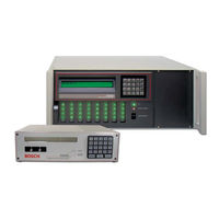
Bosch Conettix D6600 Installation And Operation Manual (88 pages)
Communications Receiver/Gateway
Brand:
Bosch
| Category:
Gateway
| Size: 2.81 MB
Table of Contents
Table of Contents
3
Emergency Procedures
6
Introduction
7
About Documentation
7
Bosch Security Systems, Inc. Product Manufacturing Dates
7
System Overview
9
Parts List
10
Quick Installation
11
Setting the Time and Date
13
Card Functions and Locations
14
D6600 Front Panel
14
Line Cards and Modules
15
D6600 Rear View
16
D6600 Internal View
17
D6100Ipv6 Front Panel
18
D6100Ipv6 Rear View
18
D6600 Specific Cards
19
D6640/D6641 Line Cards and D6645 Line Terminator Cards
19
D6640/D6641 LED Descriptions
20
Card Installation
20
D6610 CPU Card and D6615 CPU Terminator Card
22
Card Removal and Replacement
23
Printer Specifications
24
Installation
25
Installation Check List
25
Rack Mount Instructions
26
Removing Power to the Receiver
26
Power
27
Power Supply Modules
27
Main Power
27
Standby Power
27
Connecting External Batteries
27
Minimum Standby Battery
28
Minimum Standby UPS Power
29
Estimated BTU Load
29
Input and Output Ports
30
Overview of Input and Output Ports
30
UPS Monitoring through CPU Programmable Input Ports
30
Automation Link Monitoring (COM3) through CPU Programmable Output Ports
32
D6600/D6100Ipv6 Operation
33
Process Flow
33
Receiver Handshake and Kiss-Off
33
Message Verification
33
Handshake Tone Compatibility
33
Message Is Received
33
How Call Groups Work
34
Buzzer Operation
34
Reporting Devices: Primary and Secondary
34
Normal Operation Mode
35
Operating in Manual Mode
35
Keypad Menu Operation
36
Log in
36
Using the Keypad
36
Event Buffer Display
36
Current System Trouble Display
36
Software Version Display
37
Keypad Functions
37
Busy Seconds (Line Busy) Reports
38
Two-Way Audio
39
Enhancements and Changes
40
Two-Way Auto Modes of Operation
40
Network Communications
42
Conettix D6600/D6100Ipv6 Pre-Installation Requirements
46
Setting up the Conettix D6600/D6100Ipv6 over an Ethernet Network
46
Host Computer for Conettix D6600/D6100Ipv6 System Setup
46
Operation
46
Setting up the Host Computer
46
Network Failover Solution (D6600 Only)
51
Conettix Datagram Type Differences
53
Networking and Encryption
54
Special Conettix D6600 Applications
56
D6100Ipv6 Configuration Setup Instructions
57
Factory Default IP Address
57
Identifying the MAC Hardware Address
58
Obtaining an IP Address
58
Using the D6200 to Configure the D6100Ipv6
58
Configuring for Network Communication
63
D6100I Configuration Setup Instructions
64
Identifying the MAC Hardware Address
64
Obtaining an IP Address
64
Initial IP Address Assignment Using ARP.EXE
65
Using Telnet to Finish the Configuration
66
Configuration Using Telnet
67
Configuring for Network Communication
70
No Data Received Reports
72
No Data Received
72
Data Error
72
Wrong Data
72
Central Station Automation System
73
Central Station Tips
75
Back-Up Receiver
75
Computer Interface
75
D6200 Programming Software
75
Telephone Lines
75
Proper Ground
75
Radio Frequency Interference
76
Test Communicator
76
Troubleshooting Guide
77
Specifications
80
Service Information
84
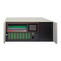
Bosch Conettix D6600 Installation And Operation Manual (38 pages)
Communications Receiver/Gateway
Brand:
Bosch
| Category:
Gateway
| Size: 1.55 MB
Table of Contents
Table of Contents
3
1 Introduction
5
Table 1: D6600/D6100I Supported Communication
5
2 Emergency Procedures
6
3 Card Functions and Locations
6
Front Panel
6
D6600
6
Figure 1: D6600 Communications
6
Receiver/Gateway (Front View)
6
Table 2: Power LED Indications
6
Line Cards and Modules
7
System Trouble LED
7
D6600 Line Cards and Modules
7
Rear View
8
Internal View
8
Receiver/Gateway (Rear View)
8
Front Panel
9
Line Cards and Modules
9
D6100I
9
Back Plate
9
4 D6600 Specific Cards
9
D6640/D6641 Line Cards and D6645 Line Terminator Card
9
Gateway (Front View)
9
Gateway (Rear View)
9
Figure 6: D6640/D6641 Line Card
9
Figure 7: D6645 Line Terminator Card
9
D6640/D6641 LED Descriptions
10
Card Installation
10
Figure 8: D6640/D6641 LED Descriptions
10
D6640/D6641Telephone Line Monitoring Voltage
11
D6610 CPU Card and D6615 CPU Terminator Card
11
D6610 CPU Card Connection
11
D6615 CPU Terminator Card
11
Card Removal and Replacement
11
Figure 9: Removing and Installing Terminator Card
11
Figure 10: D6615 CPU Terminator Card
11
5 Power Supply Modules (D6600 Only)
12
6 Printer Specifications
12
7 Installation
12
All Installations
12
UL Installations
12
Burglar Alarm Applications
13
Figure 11: Location of D6100I Battery Terminals and D6600 Battery Connector
13
Fire Alarm Applications
13
Installation Check List
13
Table 5: Parameters to be Set
13
Rack Mount Instructions
14
Removing Power to the Receiver
14
8 Standby Power
14
Connecting External Batteries
14
Minimum Standby Battery
15
Minimum Standby UPS Power
15
Figure 2: D6600 Communications Table 6: Battery Voltage Display
15
Table 7: Calculating Standby Current for the Figure 3: Receiver Card Placement
15
D6600
15
Figure 4: D6100I Communications Receiver/Table 8: Standby Current for the D6100I
15
Table 9: Minimum Standby Battery Chart
15
9 Input and Output Ports
16
UPS Monitoring through CPU Programmable Input Ports
16
Input Default Connection Configuration
16
Input Reverse Connection Configuration
16
Figure 12: D6600 Back Panel Showing Input/Output Ports
16
Figure 13: D6100I Back Panel Showing Input/Output Ports
16
Figure 14: Input Wiring for Reverse Configuration
16
Automation Link Monitoring (COM3) through CPU Programmable Output Ports
17
Figure 5: D6100I Communications Receiver/Table 10: Terminator Card Configuration
17
10 D6600/D6100I Operation
18
Process Flow
18
Receiver Handshake and Kiss-Off
18
Message Verification
18
Handshake Tone Compatibility
18
Message Is Received
18
How Call Groups Work
18
Buzzer Operation
19
Reporting Devices: Primary and Secondary
19
Normal Operation Mode
19
Operating in Manual Mode
20
Keypad Menu Operation
20
Log in
20
Using the Keypad
20
Event Buffer Display
21
Current System Trouble Display
21
Software Version Display
21
Keypad Functions
21
Table 11: Communication Links Test Outputs
21
Skip Current Automation Event
22
Line Test
22
Clear Pending Events
23
Busy Seconds (Line Busy) Reports
23
Two-Way Audio
24
Enhancements and Changes
24
Two-Way Audio Modes of Operation
25
11 Network Communications
26
Figure 15: Conettix Network System Connection Diagram - C900TTL-E/C900V2 and any Control Panel
26
12 No Data Received Reports
27
Description
27
No Data Received
27
Data Error
27
Wrong Data
27
Figure 16: Conettix Network System Connection Diagram - D9133TTL-E/DX4020 and Bosch Control Panels
27
Figure 17: no DATA RECEIVED Message
27
13 Using the Central Station Automation System with the Receiver
28
Figure 18: Receiver System - Direct Connect
28
14 Central Station Tips
29
Back-Up Receiver
29
Computer Interface
29
D6200 Programming Software
29
Telephone Lines
29
Emergency Ringers
29
Rotary Lines
29
Automation
29
Figure 19: Receiver System - Standard/Network
29
Proper Ground
30
Radio Frequency Interference
30
Test Communicator
30
15 Troubleshooting Guide
31
Table 12: Hardware Troubleshooting Guide
31
16 Specifications
34
Table 13: D6600/D6100I Specifications
34
17 Service Information
36
Advertisement
Bosch Conettix D6600 Installation And Operation Manual (36 pages)
Communications Receiver/Gateway
Brand:
Bosch
| Category:
Gateway
| Size: 1.52 MB
Table of Contents
Table of Contents
3
1 Introduction
5
2 Emergency Procedures
6
3 Card Functions and Locations
6
Front Panel
6
Figure 1: D6600 Communications Receiver/Gateway (Front View)
6
Line Cards and Modules
7
Rear View
8
Internal View
8
Figure 3: Receiver Card Placement
8
Front Panel
9
Line Cards and Modules
9
Back Plate
9
4 D6600 Specific Cards
9
D6640/D6641 Line Cards and D6645 Line Terminator Card
9
Figure 4: D6100I Communications Receiver/Gateway (Front View)
9
Figure 5: D6100I Communications Receiver/Table 8: Gateway (Rear View)
9
Figure 6: D6640/D6641 Line Card
9
Figure 7: D6645 Line Terminator Card
9
D6640/D6641 LED Descriptions
10
Card Installation
10
Figure 8: D6640/D6641 LED Descriptions
10
D6640/D6641Telephone Line Monitoring Voltage
11
Figure 9: Removing and Installing Terminator Card
11
D6610 CPU Card and D6615 CPU Terminator Card
12
D6610 CPU Card Connection
12
D6615 CPU Terminator Card
12
Card Removal and Replacement
12
5 Power Supply Modules (D6600 Only)
12
6 Printer Specifications
12
Figure 10: D6615 CPU Terminator Card
12
7 Installation
13
All Installations
13
UL Installations
13
Burglar Alarm Applications
13
Fire Alarm Applications
13
Installation Check List
13
Figure 11: Location of D6100I Battery Terminals and D6600 Battery Connector
13
Rack Mount Instructions
14
Removing Power to the Receiver
14
8 Standby Power
14
Connecting External Batteries
14
Minimum Standby Battery
15
Minimum Standby UPS Power
15
9 Input and Output Ports
15
Figure 12: D6600 Back Panel Showing Input/Output Ports
15
Figure 13: D6100I Back Panel Showing Input/Output Ports
15
Calculating Standby Current for the D6600
15
UPS Monitoring through CPU Programmable Input Ports
16
Input Default Connection Configuration
16
Input Reverse Connection Configuration
16
Automation Link Monitoring (COM3) through CPU Programmable Output Ports
16
Figure 14: Input Wiring for Reverse Configuration
16
10 D6600/D6100I Operation
17
Process Flow
17
Receiver Handshake and Kiss-Off
17
Message Verification
17
Handshake Tone Compatibility
17
Message Is Received
17
How Call Groups Work
17
Buzzer Operation
18
Reporting Devices: Primary and Secondary
18
Normal Operation Mode
18
Operating in Manual Mode
19
Keypad Menu Operation
19
Log in
19
Using the Keypad
19
Event Buffer Display
20
Current System Trouble Display
20
Software Version Display
20
Keypad Functions
20
Skip Current Automation Event
21
Line Test
21
Clear Pending Events
22
Busy Seconds (Line Busy) Reports
22
Two-Way Audio
23
Enhancements and Changes
23
Two-Way Audio Modes of Operation
24
11 Network Communications
25
Figure 15: Conettix Network System Connection Diagram - C900TTL-E/C900V2 and any Control Panel
25
12 No Data Received Reports
26
Description
26
No Data Received
26
Data Error
26
Wrong Data
26
Figure 16: Conettix Network System Connection Diagram - D9133TTL-E/DX4020 and Bosch Control Panels
26
Figure 17: no DATA RECEIVED Message
26
13 Using the Central Station Automation System with the Receiver
27
Figure 18: Receiver System - Direct Connect
27
14 Central Station Tips
28
Back-Up Receiver
28
Computer Interface
28
D6200 Programming Software
28
Telephone Lines
28
Emergency Ringers
28
Rotary Lines
28
Figure 19: Receiver System - Standard/Network Automation
28
Proper Ground
29
Radio Frequency Interference
29
Test Communicator
29
15 Troubleshooting Guide
30
Table
33
16 Specifications
33
17 Service Information
35
Bosch Conettix D6600 Operation And Installation Manual (36 pages)
Receiver/Gateway
Brand:
Bosch
| Category:
Gateway
| Size: 2.44 MB
Table of Contents
Table of Contents
3
1 Introduction
5
Documentation Conventions
6
2 Emergency Procedures
6
3 Card Functions and Locations
7
Front Panel
7
Line Cards and Modules
7
Rear View
8
Figure 3: Receiver Card Placement
8
4 D6600 Specific Cards
9
D6640/D6641 Line Cards and D6645 Line Terminator Card
9
D6640/D6641 LED Descriptions
9
Figure 4: D6640/D6641 Line Card
9
Figure 5: D6645 Line Terminator Card
9
Figure 6: D6640/D6641 LED Descriptions
9
Card Installation
10
Figure 7: Removing the Top Cover of the D6600
10
Telephone Line Monitoring Voltage
11
D6610 CPU Card and D6615 CPU Terminator Card
11
D6610 CPU Card Connection
11
D6615 CPU Terminator Card
11
Figure 10: D6615 CPU Terminator Card
11
Card Removal and Replacement
12
5 Power Supply Modules
12
6 Printer Specifications
12
7 Installation
12
All Installations
12
UL Installations
12
Burglar Alarm Applications
12
Figure 11: Location of D6600 Battery Connector
12
Fire Alarm Applications
13
Installation Check List
13
Rack Mount Instructions
13
Powering down the Receiver
13
8 Standby Power
13
Connecting External Batteries
14
Minimum Standby Battery Chart
14
Minimum Standby UPS Power
14
9 Input and Output Ports
15
UPS Monitoring through CPU Programmable Input Ports
15
Input Default Connection Configuration
15
Input Reverse Connection Configuration
15
Figure 12: D6600 Back Panel Showing Input/Output Ports
15
Figure 13: Input Wiring for Reverse Configuration
15
Automation Link Monitoring (COM3)
16
Through CPU Programmable Output Ports
16
10 D6600 Operation
16
Process Flow
16
Event Database
16
Receiver Handshake and Kiss-Off
17
Message Verification
18
Handshake Tone Compatibility
18
Message Is Received
18
How Call Groups Work
18
Buzzer Operation
18
Reporting Devices: Primary and Secondary
18
Normal Operation Mode
19
Operating in Manual Mode
19
Keypad Menu Operation
19
Log in
19
Using the Keypad
20
Event Buffer Display
20
Current System Trouble Display
20
Software Version Display
20
Keypad Functions
20
Skip Current Automation Event
21
Line Test
21
Clear Pending Events
21
Busy Seconds (Line Busy) Reports
22
Two-Way Audio
22
Enhancements and Changes
23
Two-Way Audio Modes of Operation
23
11 Network Communications
24
Figure 14: D6600 Netcom System Connection Diagram - C900TTL-E and any Control Panel
24
12 No Data Received Reports
25
Description
25
No Data Received
25
Data Error
25
Wrong Data
25
Figure 15: D6600 Netcom System Connection Diagram - D9133TTL-E and Bosch Control Panels
25
Figure 16: no DATA RECEIVED Message
25
13 Using the Central Station Automation System with the D6600
26
Figure 17: D6600 System - Direct Connect
26
Figure 18: D6600 System - Standard/Network
26
Automation
26
14 Central Station Tips
27
Back-Up Receiver
27
Computer Interface
27
D6200 Programming Software
27
Telephone Lines
27
Emergency Ringers
27
Rotary Lines
27
Proper Ground
27
Radio Frequency Interference
27
Test Communicator
27
15 Troubleshooting Guide
28
16 Specifications
31
17 Service Information
32
Bosch Conettix D6600 Installation And Operation Manual (36 pages)
Communications Receiver/Gateway
Brand:
Bosch
| Category:
Gateway
| Size: 1.53 MB
Table of Contents
Table of Contents
2
1 Introduction
3
2 Emergency Procedures
4
3 Card Functions and Locations
4
Front Panel
4
D6600
4
Line Cards and Modules
5
Rear View
6
Internal View
6
Front Panel
7
Line Cards and Modules
7
D6100I
7
Back Plate
7
4 D6600 Specific Cards
7
D6640/D6641 Line Cards and D6645 Line Terminator Card
7
D6640/D6641 LED Descriptions
8
Card Installation
8
D6640/D6641Telephone Line Monitoring Voltage
9
D6610 CPU Card and D6615 CPU Terminator Card
9
D6610 CPU Card Connection
9
D6615 CPU Terminator Card
9
Card Removal and Replacement
10
5 Power Supply Modules (D6600 Only)
10
6 Printer Specifications
10
7 Installation
10
Installation Check List
10
Rack Mount Instructions
11
Removing Power to the Receiver
11
8 Power
11
Main Power
11
Standby Power
11
Connecting External Batteries
11
Minimum Standby Battery
12
Minimum Standby UPS Power
12
9 Input and Output Ports
13
UPS Monitoring through CPU Programmable Input Ports
13
Input Default Connection Configuration
13
Input Reverse Connection Configuration
14
Automation Link Monitoring (COM3) through CPU Programmable Output Ports
14
10 D6600/D6100I Operation
15
Process Flow
15
Receiver Handshake and Kiss-Off
15
Message Verification
15
Handshake Tone Compatibility
15
Message Is Received
15
How Call Groups Work
15
Buzzer Operation
16
Reporting Devices: Primary and Secondary16
16
Normal Operation Mode
16
Operating in Manual Mode
17
Keypad Menu Operation
17
Log in
17
Using the Keypad
17
Event Buffer Display
18
Current System Trouble Display
18
Software Version Display
18
Keypad Functions
19
Skip Current Automation Event
19
Line Test
20
Clear Pending Events
20
LCD/LED Availability Test
20
Busy Seconds (Line Busy) Reports
21
Two-Way Audio
22
Enhancements and Changes
22
Two-Way Audio Modes of Operation
23
11 Network Communications
24
12 No Data Received Reports
25
Description
25
No Data Received
25
Data Error
25
Wrong Data
25
13 Central Station Automation System
26
14 Central Station Tips
27
Back-Up Receiver
27
Computer Interface
27
D6200 Programming Software
27
Telephone Lines
27
Emergency Ringers
27
Rotary Lines
27
Proper Ground
28
Radio Frequency Interference
28
Test Communicator
28
15 Troubleshooting Guide
29
16 Specifications
32
17 Service Information
34
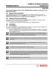
Bosch Conettix D6600 Installation Manual (4 pages)
Communications Receiver/Gateway Card Installation
Brand:
Bosch
| Category:
Gateway
| Size: 0.53 MB
Bosch Conettix D6600 Installation Supplement (4 pages)
Brand:
Bosch
| Category:
Receiver
| Size: 0.15 MB
Advertisement
Related Products
Bosch Conettix D6100IPv6
Bosch Conettix D6100i
Bosch Conettix D6680
Bosch D621 Series
Bosch D630
Bosch D626
Bosch D620
Bosch D6412
Bosch D621B
Bosch D623W
Bosch Categories
Dishwasher
Washer
Oven
Power Tool
Dryer
More Bosch Manuals
Login
Sign In
OR
Sign in with Facebook
Sign in with Google
Upload manual
Upload from disk
Upload from URL