Canon CLC5151 Reference Manual
Hide thumbs
Also See for CLC5151:
- Sending and facsimile manual (476 pages) ,
- Copying and mail box manual (468 pages)

Related Manuals for Canon CLC5151


Summary of Contents for Canon CLC5151
- Page 1 Reference Guide Please read this guide before operating this equipment. ENGLISH After you finish reading this guide, store it in a safe place for future reference.
- Page 3 Frontmatter CLC5151/CLC4040 iR C4580i/iR C4080i Reference Guide...
-
Page 4: Manuals For The Machine
Manuals for the Machine The manuals for this machine are divided as follows. Please refer to them for detailed information. The manuals supplied with optional equipment are included in the list below. Depending on the system configuration and product purchased, some manuals may not be needed. Guides with this symbol are included on the accompanying Guides with this symbol are printed manuals. - Page 5 • PS Printer Driver Installation and Instructions PS Driver Guide* CD-ROM • UFR II Printer Driver Installation and Instructions UFR II Driver Guide* CD-ROM • Mac OS X PS Printer Driver Installation and Mac PS Driver Guide* Instructions CD-ROM • Mac OS X UFR II Printer Driver Installation and Mac UFR II Driver Guide* Instructions CD-ROM...
-
Page 6: Table Of Contents
Relationship between Original Orientation and Preprinted Paper Output Chart, and index. Considerable effort has been made to ensure that this manual is free of inaccuracies and omissions. However, as we are constantly improving our products, if you need an exact specification, please contact Canon. - Page 7 Additional Information ...........xviii International Energy Star Program (CLC5151/iR C4580i Only) ....xix WEEE Directive.
- Page 8 What This Machine Can Do ..........2-2 Overview of the CLC5151/CLC4040/iR C4580i/iR C4080i ......2-5 The Touch Panel Display .
- Page 9 Parts and Their Functions ..........3-17 Finisher-X1 .
- Page 10 Changing the Language Shown on the Touch Panel Display....4-54 Reversing the Contrast of the Touch Panel Display ......4-55 Alternating the Print Output (Offset Jobs) .
- Page 11 Changing the Password and Page Limit ........6-11 Erasing the Department ID and Password .
- Page 12 Service Call Message ........... . 8-87 Contacting Your Local Authorized Canon Dealer ......8-87 Setting the Limited Functions Mode from the Service Call Message Screen .
- Page 13 Index ..............9-28 System Management of the CLC5151/CLC4040/iR C4580i/iR C4080i ....9-33 Entering the System Management Mode .
-
Page 14: Preface
Preface Thank you for purchasing the Canon CLC5151/CLC4040/iR C4580i/iR C4080i. Please read this manual thoroughly before operating the machine to familiarize yourself with its capabilities, and to make the most of its many functions. After reading this manual, store it in a safe place for future reference. -
Page 15: Keys Used In This Manual
Examples: Displays Used in This Manual Screen shots of the touch panel display used in this manual are those taken when the CLC5151 has the Color Universal Send Kit activated, and the following optional equipment attached to it: the Super G3 FAX Board, Color Image Reader-F1, Saddle Finisher-W2, Puncher Unit-AG1, and Cassette Feeding Unit-Z1. -
Page 16: Illustrations Used In This Manual
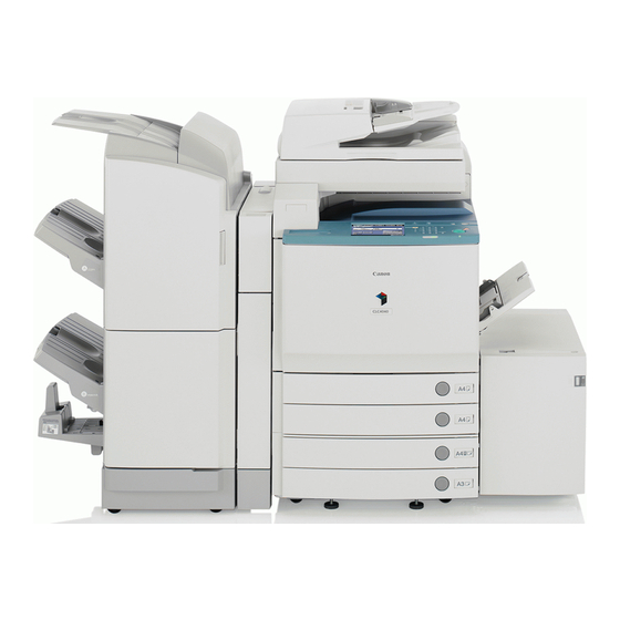
Illustrations Used in This Manual Illustrations used in this manual are those displayed when the CLC5151 has the following optional equipment attached to it: the Color Image Reader-F1, Saddle Finisher-W2, Puncher Unit-AG1, and Cassette Feeding Unit-Z1. -
Page 17: Operations And Terms Used In This Manual
Operations and Terms Used in This Manual This machine makes effective use of memory to perform print operations efficiently. For example, as soon as the machine has scanned the original that you want to copy, it can immediately scan the next person's original. You can also print from this machine, using a function other than the Copy function. - Page 18 Copying Printing data scanned from an original, followed by finishing options, such as stapling.
-
Page 19: Legal Notices
Legal Notices Equipment Name According to the Safety Regulations of the regions where this equipment is sold, a name in the following ( ) may be registered instead. CLC5151 (F148000) CLC4040/iR C4580i (F148100) iR C4080i (F148200) Preventing Counterfeit Documents This machine includes a function for aiding in the prevention of counterfeit documents. If you are copying documents that resemble paper money closely, you may be unable to get an appropriate image. -
Page 20: Laser Safety
Laser Safety This Product is certified as a Class I laser product under IEC60825-1:1993 and EN60825-1:1994. This means that the product does not produce hazardous laser radiation. Since radiation emitted inside the product is completely confined within protective housings and external covers, the laser beam cannot escape from the machine during any phase of user operation. -
Page 21: International Energy Star Program (Clc5151/Ir C4580I Only)
International Energy Star Program (CLC5151/iR C4580i Only) As an Energy Star Partner, Canon USA, Inc. has determined that this machine meets the Energy Star Program guidelines for energy efficiency. The International Energy Star Office Equipment Program is an international programme that promotes energy saving through the use of computers and other office equipment. -
Page 22: Trademarks
Trademarks Canon, the Canon logo, CLC, iR, MEAP, and NetSpot are registered trademarks, and the MEAP logo and NetSpot Accountant are trademark of Canon Inc. in the United States and may also be trademarks or registered trademarks in other countries. -
Page 23: Copyright
Canon Inc. This product includes free software and/or software modules that are licensed by Canon Inc. or its licensors from third parties. Use and distribution of this software and/or software modules are subject to conditions (a) through (e) below. - Page 24 Redistribution and use in source and binary forms are permitted provided that the above copyright notice and this paragraph are duplicated in all such forms and that any documentation, advertising materials, and other materials related to such distribution and use acknowledge that the software was developed by the University of California, Berkeley.
-
Page 25: Disclaimers
Disclaimers The information in this document is subject to change without notice. CANON INC. MAKES NO WARRANTY OF ANY KIND WITH REGARD TO THIS MATERIAL, EITHER EXPRESS OR IMPLIED, EXCEPT AS PROVIDED HEREIN, INCLUDING WITHOUT LIMITATION, THEREOF, WARRANTIES AS TO MARKETABILITY, MERCHANTABILITY, FITNESS FOR A PARTICULAR PURPOSE OF USE OR NON-INFRINGEMENT. - Page 26 In Order to Avoid Unauthorized Use of the Machine Unauthorized copies can be prevented by using the optional Key Switch Unit to manage the operation of the CLC5151/CLC4040/iR C4580i/iR C4080i. The use of this key should be strictly supervised. Security Key...
-
Page 27: Important Safety Instructions
If these items are dropped or spilled inside the machine, immediately turn OFF the main power switch, and disconnect the power cord from the power outlet. Then, contact your local authorized Canon dealer. - Necklaces and other metal objects - Cups, vases, flowerpots, and other containers filled with water or liquids... - Page 28 CAUTION • Do not install the machine in unstable locations, such as unsteady platforms or inclined floors, or in locations subject to excessive vibrations, as this may cause the machine to fall or tip over, resulting in personal injury. • Never block the ventilation slots and louvers on the machine. These openings are provided for proper ventilation of working parts inside the machine.
-
Page 29: Power Supply
Power Supply WARNING • Do not damage or modify the power cord. Also, do not place heavy objects on the power cord, or pull on or excessively bend it, as this could cause electrical damage and result in a fire or electrical shock. -
Page 30: Handling
• If the machine makes strange noises, or gives off smoke, heat, or strange smells, immediately turn OFF the main power switch, and disconnect the power cord from the power outlet. Then, contact your local authorized Canon dealer. Continued use of the machine in this condition may result in a fire or electrical shock. - Page 31 CAUTION • Do not place heavy objects on the machine, as they may tip over or fall resulting in personal injury. • Close the feeder/platen cover gently to avoid catching your hands, as this may result in personal injury. • Do not press down hard on the feeder/platen cover when using the platen glass to make copies of thick books.
- Page 32 • Do not place your hands in the part of the tray where stapling is performed (near the rollers) when a finisher is attached, as this may result in personal injury. Finisher-X1 Finisher-W1/Saddle Finisher-W2 • The laser beam can be harmful to human bodies. Since radiation emitted inside the product is completely confined within protective housings and external covers, the laser beam cannot escape from the machine during any phase of user operation.
- Page 33 • Do not remove the following caution labels which are attached to the machine. • If the laser beam escapes from the machine, exposure may cause serious damage to your eyes. xxxi...
-
Page 34: Maintenance And Inspections
Maintenance and Inspections WARNING • When cleaning the machine, first turn OFF the main power switch, then disconnect the power cord. Failure to observe these steps may result in a fire or electrical shock. • Disconnect the power cord from the power outlet regularly, and clean the area around the base of the power plug's metal pins and the power outlet with a dry cloth to ensure that all dust and grime is removed. - Page 35 CAUTION • The fixing unit and its surroundings inside the machine may become hot during use. When removing jammed paper or when inspecting the inside of the machine, do not touch the fixing unit and its surroundings, as doing so may result in burns or electrical shock. •...
-
Page 36: Consumables
Consumables WARNING • Do not burn or throw used toner cartridges into open flames, as this may cause the toner remaining inside the cartridges to ignite, resulting in burns or a fire. • Do not store toner cartridges or copy paper in places exposed to open flames, as this may cause the toner or paper to ignite, resulting in burns or a fire. -
Page 37: Periodic Inspection Of The Breaker
IMPORTANT • Make sure that the main power is turned OFF, before inspecting the breaker. • If a malfunction occurs after an inspection, contact your local authorized Canon dealer. Checking the Breaker Push the test button with the tip of a ball-point pen, or a similar object. - Page 38 • If the breaker lever does not switch to the OFF (" " side) position, despite carrying out the above procedure two or three times, contact your local authorized Canon dealer. Switch the breaker lever to ON ("I" side). ( I side)
- Page 39 Press the main power switch to ON ("I" side). ( I side) side) Fill in the check sheet, located on the next page, to document your periodic inspections of the breaker. xxxvii...
-
Page 40: Check Sheet For The Periodic Inspection Of The Breaker
Fill in the date of inspection and the name of the inspector. When the inspection is completed successfully, write a check mark under "OK." If not, contact your local authorized Canon dealer. (Also, write a check mark under "NG" (No Good).) Result... -
Page 41: Before You Start Using This Machine
Before You Start Using This Machine CHAPTER This chapter describes what you should know before using this machine, such as parts and their functions, and how to turn ON the main power. Installation Location and Handling ........... . . 1-2 Installation Precautions. -
Page 42: Installation Location And Handling
Installation Location and Handling This section describes precautions for installation location and handling. We recommend that you read this section prior to using this machine. Installation Precautions Avoid Installing the Machine in the Following Locations Avoid locations subject to temperature and humidity extremes, whether low or high. - Page 43 Avoid poorly ventilated locations. This machine generates a slight amount of ozone during normal use. Although sensitivity to ozone may vary, this amount is not harmful. Ozone may be more noticeable during extended use or long production runs, especially in poorly ventilated rooms. It is recommended that the room be appropriately ventilated, sufficient to maintain a comfortable working environment, in areas of machine operation.
- Page 44 Avoid locations that are subject to vibration. For example, avoid installing the machine on unstable floors or stands. Avoid exposing the machine to rapid changes in temperature. If the room in which the machine is installed is cold but rapidly heated, water droplets (condensation) may form inside the machine.
-
Page 45: Select A Safe Power Supply
Avoid installing the machine near televisions, radios, or similar electronic equipment. The machine might interfere with sound and picture signal reception. Insert the power plug into a dedicated power outlet, and maintain as much space as possible between the machine and other electronic equipment. -
Page 46: Provide Adequate Installation Space
Provide Adequate Installation Space Provide enough space on each side of the machine for unrestricted operation. The optional Color Image Reader-F1 is attached. 100 mm or more 1,250 mm 1,660mm The optional Color Image Reader-F1, Saddle Finisher-W2, Puncher Unit-AG1, and Paper Deck-Y1 are attached. 100 mm or more 1,250 mm 2,700 mm... -
Page 47: Moving The Machine
Moving the Machine If you intend to move the machine, even to a location on the same floor of your building, contact your local authorized Canon dealer beforehand. Handling Precautions Do not attempt to disassemble or modify the machine. Some parts inside the machine are subject to high-voltages and temperatures. - Page 48 If there is smoke, or unusual noise, immediately turn the main power switch OFF, disconnect the power cord from the outlet, and call your local authorized Canon dealer. Using the machine in this state may cause a fire or electrical shock. Also, avoid placing objects around the power plug so that the machine can be disconnected whenever necessary.
- Page 49 Do not use flammable sprays, such as spray glue, near the machine. There is a danger of ignition. This machine generates a slight amount of ozone during normal use. Although sensitivity to ozone may vary, this amount is not harmful. Ozone may be more noticeable during extended use or long production runs, especially in poorly ventilated rooms.
- Page 50 Neither Canon nor any service provider will be liable for damages for loss of data stored on the product's hard disk drive. (See the terms of the product's Limited Warranty for more details).
-
Page 51: Parts And Their Functions
Parts and Their Functions This section provides you with the names and functions of all the parts on the outside and inside of the main unit, control panel, and the touch panel display. An illustration of the machine with some optional equipment attached to it is also provided. For more information on optional equipment, parts and their functions, see Chapter 3, "Optional Equipment."... - Page 52 a Centre Output Tray e Test Button Prints are output to this tray. Press this button to periodically test the circuit breaker. b Control Panel f Breaker Includes the keys, touch panel display, and indicators Detects excess current or leakage current. (See "Periodic required for operating the machine.
-
Page 53: Internal View
Internal View The optional Color Image Reader-F1 and Cassette Feeding Unit-Z1 are attached. 1-13 Parts and Their Functions... - Page 54 a Platen Glass (Color Image Reader-E1 or Color f Right Cover Image Reader-F1) Open this cover when clearing a paper jam inside the main unit. (See "Screens Indicating the Locations of Paper Place originals here when scanning books, thick originals, Jams,"...
-
Page 55: Control Panel Parts And Functions
Use to designate areas on the original to copy or scan. If Press when setting or enabling Department ID you lose the edit pen, contact your local authorized Canon Management. dealer. Do not use an object with a sharp end, such as a pencil or ballpoint pen, in place of the edit pen. -
Page 56: Main Power And Control Panel Power
Main Power and Control Panel Power The machine is provided with two power switches, a main power switch and a control panel power switch, as well as a breaker that detects excess current or leakage current. How to Turn ON the Main Power This section explains how to turn ON the main power. - Page 57 Press the main power switch to ON ("I" side). The main power switch is located on the right side of the machine. ( I side) side) The main power indicator on the control panel lights when the main power switch is turned ON. IMPORTANT If the main power indicator on the control panel does not light even though the main power switch is ON, be sure to check the breaker to see if it is OFF.
- Page 58 The screen below is displayed when the machine is ready to scan. The machine is ready to scan in approximately four minutes (for the CLC5151) or five minutes (for the CLC4040/iR C4580i/iR C4080i) after the screen above appears (at a room temperature of 20°).
- Page 59 If login authentication by a login service (SDL or SSO) is not set, and MEAP is selected as the initial function in Common Settings (from the Additional Functions screen): The Start Up screen is displayed until the machine is ready to scan. After the Start Up screen disappears, the MEAP Start Up screen is displayed.
- Page 60 The MEAP Application screen is displayed. If login authentication by a login service (SDL or SSO) is set: The Start Up screen is displayed until the machine is ready to scan. 1-20 Main Power and Control Panel Power...
- Page 61 After the Start Up screen disappears, the MEAP Start Up screen is displayed regardless of the Set as Initial Function settings. IMPORTANT • If you turn OFF the main power, wait at least 10 seconds before turning the main power back ON. For instructions on restarting (turning the main power switch OFF and then ON) the machine, see "Main Power and Control Panel Power,"...
-
Page 62: Control Panel Power Switch
I-fax and fax documents can also be received while the machine is in the Sleep mode. • It takes up to four minutes for the CLC5151 or up to five minutes for the CLC4040/iR C4580i/iR C4080i to recover after the Sleep mode is deactivated. - Page 63 Press and hold the control panel power switch for more than three seconds. If the machine is in the Sleep mode, press the control panel power switch one time to cancel the Sleep mode, and then press and hold the control panel power switch again for more than three seconds.
- Page 64 NOTE • Jobs that are displayed on the job confirmation screen are: - Current copy, fax, and print jobs (including secured print jobs) - Copy and print jobs (including secured print jobs) that are waiting to be processed • On the job confirmation screen, the current job is displayed on the first line, and the other jobs are processed in the order in which they were reserved (up to seven jobs).
- Page 65 Note that Canon will not be liable for any damages resulting from the loss of data on the hard disk drive. For more information, contact your local authorized Canon dealer.
- Page 66 NOTE • It may take up to 30 minutes for the machine to completely shut down because of the internal cooling down process. • It may take more than one hour for the machine to completely shut down depending on the application you are using.
-
Page 67: System Settings
System Settings It is necessary to set up the machine before using it on a network, as a printer, or with the Fax function. To set up the machine, refer to the following guides or sections for instructions: Connecting the Machine to the Network See the Network Quick Start Guide. - Page 68 1-28 System Settings...
-
Page 69: Basic Operations
Overview of the CLC5151/CLC4040/iR C4580i/iR C4080i ........ -
Page 70: What This Machine Can Do
Copy rich array of input and output features that can greatly enhance your efficiency. Equipped with features that meet the needs of document work in a digitized office, the CLC5151/ Send Mail Box CLC4040/iR C4580i/iR C4080i represents the ultimate in digital multitasking machines. -
Page 71: Sending Function
Mail Box Function See the Copying and Mail Box Guide The Mail Box function enables you to save image or document data that has been scanned from the scanner unit, or created on a PC and sent to the machine's internal hard disk. The saved data can be Printing merged documents Scanning... - Page 72 Printing* See the PS/PCL/UFR II Printer Guide You can upgrade the CLC5151/CLC4040 to a high-speed network printer by installing the optional Color Network Printer Unit (The UFR II/PCL/PS print function is standard equipped with the iR C4580i/ iR C4080i.). Sending data...
-
Page 73: Overview Of The Clc5151/Clc4040/Ir C4580I/Ir C4080I
[Copy], [Send], [Mail Box], [Print Job], [Scan], or [System Monitor] to change functions. (See "Initial Function at Power ON," on p. 4-25.) To display other functions, such as an installed MEAP (Multifunctional Embedded Application Platform) application, press [ ]. Overview of the CLC5151/CLC4040/iR C4580i/iR C4080i... - Page 74 Keys Displayed on the Touch Panel Display The Copy Basic Features screen is shown as an example below. Page 1 of the Basic Features Screen MEAP Application Screen (Group A) Page 2 of the Basic Features Screen (Group B) Overview of the CLC5151/CLC4040/iR C4580i/iR C4080i...
- Page 75 You can also customize the order of the function keys in Function Display Settings in Common Settings (from the Additional Functions screen). (See "Initial Function at Power ON," on p. 4-25.) Overview of the CLC5151/CLC4040/iR C4580i/iR C4080i...
-
Page 76: Various Touch Panel Display Screens
Color Image Reader-E1 or Color Image Reader-F1, Color Universal Send Kit, Color Network Printer Unit, and Web Access Software NOTE [Fax] is displayed only if the optional Color Universal Send Kit is not activated. Overview of the CLC5151/CLC4040/iR C4580i/iR C4080i... -
Page 77: Adding New Functions
Installing MEAP applications enables you to utilize new customizable functions for the machine. You can also uninstall these applications. NOTE For instructions on installing and uninstalling MEAP applications, see the MEAP SMS Administrator Guide. Overview of the CLC5151/CLC4040/iR C4580i/iR C4080i... - Page 78 CD-ROM. For instructions on installing Security Agent, see the Readme.pdf file on the CD-ROM. NOTE Default Authentication is selected as the default login service. For instructions on selecting and setting a login service other than default authentication, see the MEAP SMS Administrator Guide. 2-10 Overview of the CLC5151/CLC4040/iR C4580i/iR C4080i...
-
Page 79: Specifying Settings
• Network Settings: The Network Guide The Additional Functions Screen The System Functions Screen IMPORTANT Several items may not be displayed if neither the optional Color Image Reader-E1 nor the Color Image Reader-F1 is attached. 2-11 Overview of the CLC5151/CLC4040/iR C4580i/iR C4080i... -
Page 80: Functions That Conserve Power
NOTE The Energy Saver mode's energy conservation level can be set to '-10%', '-25%', '-50%', or 'None'. (See "Energy Saver Mode," on p. 4-35.) 2-12 Overview of the CLC5151/CLC4040/iR C4580i/iR C4080i... -
Page 81: Auto Sleep Mode
The Low-Power mode conserves energy by turning OFF the control panel, and reducing the power consumption of the fixing unit (only for the CLC5151) or turning OFF the power of optional equipment (only for the CLC4040/iR C4580i/iR C4080i) when the machine is idle for a certain period of time (after the last print job or key operation is performed). -
Page 82: Checking, Changing, And Cancelling Print Jobs
The System Monitor Screen (Print) The System Monitor Screen (Device) On the Print Job screen, you can confirm, cancel, or change the priority of print jobs. The Print Job Screen 2-14 Overview of the CLC5151/CLC4040/iR C4580i/iR C4080i... -
Page 83: Checking Job And Device Status
Copy Job Send/Fax Job Mail Box Job Printer Job Report Job Network Scan Job Additional Functions Job Icon (Machine Status) Description Error Paper Jam Staple Jam Replace Toner Cartridge Replace Waste Toner Container 2-15 Overview of the CLC5151/CLC4040/iR C4580i/iR C4080i... -
Page 84: Displaying A Help Screen
Copying or Mail Box function may bring up a guidance screen with an explanation of that mode. List Screen Displays a list of the functions selected on the main menu. 2-16 Overview of the CLC5151/CLC4040/iR C4580i/iR C4080i... - Page 85 The [Try It] key is only displayed on the Explanation Screen for some Copy functions. Example: The procedure for making a copy of a photo. Press [Making Copies] [Original Type Settings]. Check the detailed information for the function. Press [Try It] [Yes] to try using the function. 2-17 Overview of the CLC5151/CLC4040/iR C4580i/iR C4080i...
-
Page 86: Reading Messages From The System Manager
• For instructions on erasing the message board, see "Clearing the Message Board," on p. 6-23. Types of Message Boards The following three types of message boards are available: A Message Board without [Done] 2-18 Overview of the CLC5151/CLC4040/iR C4580i/iR C4080i... - Page 87 NOTE The Auto Clear mode does not activate if Auto Clear Time is set to '0'. A Message Board Where the Message Appears in the Job/Print Status Display Area Job/Print Status Display Area 2-19 Overview of the CLC5151/CLC4040/iR C4580i/iR C4080i...
-
Page 88: Other Useful Functions
Job/Print Status Display Area. NOTE The approximate time is not displayed when the wait time is less than one minute. (See "Number of Copies/Wait Time Status Display," on p. 4-58.) 2-20 Overview of the CLC5151/CLC4040/iR C4580i/iR C4080i... - Page 89 There are four different paper supply indicators, as shown below: Display Remaining Paper Paper drawer is approximately 50% - 100% full. Paper drawer is approximately 10% - 50% full. Paper drawer is less than 10% full. Paper drawer is empty. 2-21 Overview of the CLC5151/CLC4040/iR C4580i/iR C4080i...
-
Page 90: Auto Orientation
Insertion, Staple (Double), Transparency Interleaving, Framing, XY Zoom, Shift, or Image Repeat mode is set, or a nonstandard paper size is specified. (See Chapter 8, "Customizing Settings," in the Copying and Mail Box Guide.) 2-22 Overview of the CLC5151/CLC4040/iR C4580i/iR C4080i... -
Page 91: Using The Touch Panel Display
Using the Touch Panel Display This section describes the keys that are frequently used on the touch panel display. Information on how to adjust the brightness of the touch panel display is also provided. CAUTION Press the touch panel display keys gently with your fingers or the edit pen. Do not press the touch panel display with a pencil, ballpoint pen, or other sharp objects that can scratch the surface of the touch panel display or break it. -
Page 92: Touch Panel Key Display
Touch Panel Key Display When you press a key on the touch panel display, that key is highlighted, and the corresponding mode is set. When you set certain modes, the characters on some keys may become grayed out. You cannot press keys that are grayed out. This means that you cannot set these modes in combination with the presently set mode. -
Page 93: Numeric Keys
Keys that have a coloured triangle ( ) in the lower right corner and that appear on screens for storing settings, are keys that already have settings stored in them. Settings Are Stored No Settings Are Stored Keys That Display a Drop-Down List Pressing a key that has a down triangle ( ) to the right of the name of the selection, displays a drop-down list containing other setting options. -
Page 94: Adjusting The Brightness
Adjusting the Brightness If the touch panel display is difficult to view, use the display contrast dial on the control panel to adjust its brightness. Lighter Darker NOTE To make the touch panel display brighter, turn the dial counterclockwise. To make it darker, turn the dial clockwise. -
Page 95: Entering Characters From The Touch Panel Display
The procedure for entering characters with the entry mode is as follows. Entry Mode Example Procedure Alphanum. Canon Enter 'Canon'. Symbol é Press [é]. To enter uppercase letters, press [Shift]. To enter a space, press [Space]. To move the cursor, press [ ] or [ ]. -
Page 96: Values In Inches
NOTE • If you make a mistake when entering characters, press [ ] or [ ] to position the cursor press [Backspace] to delete the characters enter the correct characters. • To delete all of the characters you have entered, press •... -
Page 97: Entering The Department Id And Password
Entering the Department ID and Password If Department ID Management has been set, the Department ID and password must be entered before using this machine. NOTE • For instructions on setting the Department ID and password, see "Department ID Management," on p. - Page 98 NOTE If you make a mistake when entering the Department ID or password, press enter the correct values. Press (Log In/Out). WXYZ Log In/Out The Basic Features screen of the selected function appears on the touch panel display. NOTE If the Department ID or password that you entered is incorrect, the message <This number has not been stored.
- Page 99 When your operations are complete, press (Log In/Out) on the control panel. If you are using a control card, remove the control card, and take it with you. (See "Card Reader-D1," on p. 9-18.) WXYZ Log In/Out NOTE • To perform operations again, you have to re-enter your Department ID and password. •...
-
Page 100: Using A Login Service
Using a Login Service If you are managing the machine with a login service, such as SDL (Simple Device Login) or SSO (Single Sign-On), enter the user name and password before using this machine. NOTE • SDL and SSO are used as examples to explain the procedure. However, if you are using a different login service, the login procedure may vary. - Page 101 IMPORTANT • To use the Domain Authentication system of SSO (including when performing domain authentication with the 'Domain Authentication + Local Device Authentication' system), a Windows server in which Active Directory is installed and Security Agent are necessary. • If there is more than a 30 minute time difference between the current time set in the computer's registry using Windows Active Directory and the time set on the machine, an error will occur if you log on using the Domain Authentication system of SSO (including when performing domain authentication with the 'Domain Authentication + Local Device Authentication' system).
- Page 102 Enter the user name press [OK]. Press [Password]. The SDL Login Screen 2-34 Using a Login Service...
- Page 103 Enter the password press [OK]. NOTE If you are using the Domain Authentication user authentication system of SSO (including the 'Domain Authentication + Local Device Authentication' user authentication system), select the Login destination from the drop-down list. Press [Log In]. You can also press (Log In/Out) instead of [Log In] to log on.
- Page 104 When your operations are complete, press (Log In/Out) on the control panel. WXYZ Log In/Out The screen for entering the user name and password appears. NOTE • To perform operations again, you have to re-enter your user name and password. •...
-
Page 105: Placing Originals
Placing Originals You can scan originals using this machine only if the optional Color Image Reader-E1 or Color Image Reader-F1 is attached. Place your originals on the platen glass or into the feeder, depending on the size and type of the original, and the copy modes that you want to use. -
Page 106: Orientation
Orientation You can place an original either vertically or horizontally. Always align the top edge of your original with the back edge of the platen glass (by the arrow in the top left corner) or the back edge of the feeder. Platen Glass Place the original Place the original... -
Page 107: Platen Glass
NOTE • If the top edge of the original is not aligned with the back edge of the platen glass (by the arrow in the top left corner), your original may not be scanned correctly, depending on the copy mode that you have set. - Page 108 Lift the feeder/platen cover. Sensor IMPORTANT This machine is equipped with an open/close sensor on the feeder/platen cover (see circled area in the above illustration). When placing originals on the platen glass, lift the feeder/platen cover approximately 300 mm so that the sensor detaches from the feeder/platen cover. If the sensor does not detach from the feeder/platen cover, the size of the originals may not be detected correctly.
- Page 109 The surface of the original that you want to copy must be placed face down. Align the top edge of your original with the back edge of the platen glass (by the arrow in the top left corner). Place books and other bound originals on the platen glass in the same way. NOTE When you are enlarging an A4 or A5 original onto A3 paper, place the original horizontally on the platen glass, and align it with the A4R or A5R marks.
- Page 110 CAUTION • Close the feeder/platen cover gently to avoid catching your hands, as this may result in personal injury. • Do not press down hard on the feeder/platen cover when using the platen glass to make copies of thick books. Doing so may damage the platen glass and result in personal injury.
-
Page 111: Feeder (Color Image Reader-F1)
Feeder (Color Image Reader-F1) You should use the feeder when you want to copy several originals at the same time. Place the originals into the feeder and press . The machine automatically feeds the originals to the platen glass and scans them. Two-sided originals can also be automatically turned over and scanned as two-sided documents. - Page 112 Adjust the slide guides to fit the size of your originals. Neatly place your originals with the side to be copied face up into the original supply tray. Place your originals as far into the feeder as they will go, until the Original Set indicator is lit. Original Set Indicator 2-44 Placing Originals...
- Page 113 If any dirt on the original scanning area is detected when the originals are placed in the feeder, the following screen appears. Even though streaks may appear on the copies, you can continue to scan your documents by pressing [Done]. It is recommended, however, that you open the feeder, clean the scanning area, and then close the feeder.
-
Page 114: Making Prints Using The Stack Bypass
Making Prints Using the Stack Bypass If you are making prints on tracing paper, labels, tab paper, transparencies, nonstandard paper size stock, or envelopes, load the paper stock into the stack bypass. IMPORTANT • Note the following points when using the stack bypass: - Paper Quantity: one to approximately 100 sheets (80 g/m ), stack approximately 10 mm high) - Paper Size: 100 mm x 148 mm to 320 mm x 457 mm... - Page 115 Manual Paper Selection mode when scanning these types of originals: - Highly transparent originals, such as transparencies - Originals with an extremely dark background • Envelopes may be creased in the printing process. • For high-quality printouts, use paper recommended by Canon. 2-47 Making Prints Using the Stack Bypass...
-
Page 116: Standard Size
Standard Size You can select standard inch paper, or A or B series paper. Irreg. Size You can load nonstandard paper sizes (100 mm x 148 mm to 320 mm x 457 mm). If you are using A5 paper, load the paper horizontally. Envelope The following envelopes can be loaded into the stack bypass: •... - Page 117 If the paper you want to specify is already loaded in the stack bypass: Press [Paper Select] [Stack Bypass] select the paper size and type loaded in the stack bypass proceed to step 6. If the paper loaded in the stack bypass is not the paper that you want to specify: Check to see if any job is reserved.
- Page 118 Load the paper into the stack bypass. Make sure that the height of the paper stack does not exceed the loading limit mark ( When you use the stack bypass to make copies, straighten out curled papers prior to use, as shown below.
- Page 119 To print on the back side of preprinted paper, load the preprinted paper face up into the stack bypass, as shown in the illustration below. Feeding Direction When copying on the back side of a preprinted sheet IMPORTANT When loading paper into the stack bypass, align the paper stack neatly between the slide guides. If the paper is not loaded correctly, a paper jam may occur.
- Page 120 If you are loading tab paper into the stack bypass: Load the tab paper into the stack bypass, as shown below. Feeding Direction IMPORTANT • Make sure that the side to be printed on is placed face up. • Make sure that the first sheet of tab paper to be printed on is placed on top. If you are loading envelopes into the stack bypass: Take five envelopes, loosen them as shown, and then stack them together.
- Page 121 Place the envelopes on a clean, level surface, and press all the way around the envelopes by hand, in the direction of the arrows, to remove any curls. Repeat this step five times for each set of five envelopes. If you are using ISO-C5, COM10, or Monarch envelopes, hold down the four corners of the envelopes firmly, so that they and the sealed or glued portion stay flat.
- Page 122 IMPORTANT • Do not use envelopes that have glue attached to their flaps, as the glue may melt due to the heat and pressure of the fixing unit. • Take particular care to spread the envelopes out in the direction that they will be fed. •...
- Page 123 Select the desired paper size. If you want to select a standard paper size: Select the desired paper size press [Next]. NOTE To select an inch paper size, press [Inch-size]. If you want to select an irregular paper size: Press [Irreg. Size]. 2-55 Making Prints Using the Stack Bypass...
- Page 124 Enter the size of the paper using the numeric keys on the touch panel display. Press [X] enter a value. Press [Y] enter a value. Press [OK]. You can also select a size key ([S1] to [S5]) containing a stored paper size setting, instead of entering values.
- Page 125 If you want to select an envelope size: Press [Envelope]. Select the envelope type press [OK]. IMPORTANT If the envelope type is not selected correctly, a paper jam will occur. 2-57 Making Prints Using the Stack Bypass...
- Page 126 Press [OK] proceed to step 6. If the following screen is displayed, press [OK] adjust the width of the slide guides specify the desired paper size. If the following screen is displayed, adjust the width of the slide guides to match the paper size stored in Stack Bypass Standard Settings, or set Stack Bypass Standard Settings to 'Off' in Common Settings (from the Additional Functions screen).
- Page 127 Select the desired paper type press [OK]. If you are printing on the back side of a previously printed sheet, press [2nd Side of 2-Sided Page]. NOTE • [Transparency] can be selected only if [A4] or [A4R] is selected as the paper size. •...
- Page 128 If the Copy function is selected, place your originals select the desired copy settings. If you are printing documents that are stored in an inbox, this step is not necessary. Press If you are printing documents that are stored in an inbox, press [Start Print]. Scanning starts.
-
Page 129: Multifunctional Operations
Multifunctional Operations The CLC5151/CLC4040/iR C4580i/iR C4080i offers the user many functions, such as printing, scanning, copying, and sending, which can be used together. The following table provides you with the details of multifunctional operations. : Available : Unavailable : Available, but with conditions... - Page 130 *1 The machine's performance may be affected if image processing, such as compression, enlargement/reduction, and rotation are carried out. *2 The output order of competing jobs varies, depending on whether an optional finisher is attached. - When an optional finisher is attached: one set is output alternately for each job - When an optional finisher is not attached: one page is output alternately for each job *3 The machine's processing speed may be slower.
-
Page 131: Available Paper Stock
Available Paper Stock The paper types that can be used with this machine are shown in the following table. Icons indicating the type of paper loaded in each paper drawer can be displayed on the paper selection screen if you store that information in the machine beforehand. (See "Identifying the Type of Paper in a Paper Source,"... - Page 132 : Available : Unavailable Paper Source Paper Size Width x Length Paper Stack Drawer 1, 2, Paper Deck Bypass 3, 4 305 mm x 457 mm SRA3 320 mm x 450 mm 297 mm x 420 mm 297 mm x 210 mm 210 mm x 297 mm 148 mm x 210 mm ISO-B5...
- Page 133 Optional Equipment CHAPTER This chapter describes the uses of optional equipment, and their special functions. System Configuration ............. . . 3-2 Optional Equipment .
-
Page 134: System Configuration
System Configuration This section provides you with illustrations of all the optional equipment that can be attached to the machine, and shows you examples of different system configurations. Optional Equipment System Configuration... - Page 135 a Color Image Reader-E1 h Paper Deck-Y1 The Color Image Reader-E1 enables the machine to scan The Paper Deck-Y1 provides an additional source of paper and read images for copying. Its platen cover secures the for printing jobs. originals placed on the platen glass. The Paper Deck-Y1 holds up to 2,700 sheets of paper (80 g/m b Copy Tray-M1...
-
Page 136: Sample System Configurations
The illustrations below are only examples of some of the possible system configurations. For information on the complete range of optional equipment configurations, contact your local authorized Canon dealer. The optional Color Image Reader-F1, Plain Pedestal-E1, Finisher-X1, and Card Reader-D1 are attached. -
Page 137: System Options
Installing the Super G3 FAX Board enables you to fax documents that have been created in applications directly from your PC via a network. NOTE The Canon Fax Driver is supplied with the Super G3 FAX Board, and enables you to send fax images from a PC via the machine. Color Universal Send Kit The Color Universal Send Kit enables you to send scanned documents via e-mail or I-fax, as well as send scanned data to be stored in file servers or User Inboxes. -
Page 138: Secure Watermark
Send PDF Advanced Feature Set as standard, therefore you do not need to activate this option. • If you are using the CLC5151/CLC4040, to use the features of the Universal Send PDF Advanced Feature Set, it must be activated after the Color Universal Send Kit has been activated. - Page 139 Security Expansion Board The Security Expansion Board is necessary to activate the optional iR Security Kit. iR Security Kit The iR Security Kit enables you to erase the contents of the machine's hard disk from a PC, as well as set the machine so that the general user cannot view the job logs.
-
Page 140: Available Combinations Of Options
Available Combinations of Options This table describes the optional equipment that is needed to use each function, the available combinations of options that can be installed simultaneously, and the limitations when installing optional equipment. Simultaneous Installation Optional Machine Function Equipment Needed Required Limitations Copy Function... - Page 141 CLC4040 only) has been expanded to 1,536 MB. PDL Print Function The Color Network Printer Unit can (required for Color Network be attached only to the CLC5151/ CLC5151/CLC4040 Printer Unit CLC4040. only) The Copy Tray-N1 and Copy Collate...
-
Page 142: Utilities
NetSpot Device Installer NetSpot Device Installer is a utility for specifying the initial settings of Canon devices connected to a network. Available on the CD-ROM, NetSpot Device Installer can be accessed directly without installation, enabling network users to quickly and easily specify the initial settings of network devices. -
Page 143: Cassette Feeding Unit-Z1
Cassette Feeding Unit-Z1 If you attach the Cassette Feeding Unit-Z1 to the machine, you have two additional paper sources for print jobs. Up to 550 sheets of paper (80 g/m ) can be loaded into each drawer of the cassette feeding unit. -
Page 144: Optional Accessories
Optional Accessories FL Cassette-X1 This cassette can be adjusted to hold various paper sizes. (See "Adjusting a Paper Drawer to Hold a Different Paper Size," on p. 7-7.) • Available Locations: Paper Drawers 1, 2, 3, or 4 • Available Paper Sizes: 305 mm x 457 mm, A3, A4, A4R, or A5R. 3-12 Cassette Feeding Unit-Z1... -
Page 145: Paper Deck-Y1
Paper Deck-Y1 If you attach the Paper Deck-Y1 to the machine, you have one additional source of paper for print jobs. Up to 2,700 sheets of paper (80 g/m ) can be loaded into the paper deck. IMPORTANT If the machine is in the Sleep mode (the touch panel is not displayed, and only the main power indicator is lit), you may not be able to open the paper deck. -
Page 146: Plain Pedestal-E1
Plain Pedestal-E1 The Plain Pedestal-E1 serves as an electrical outlet for any one of the finishers and the paper deck when the cassette feeding unit is not attached. This pedestal can also be used for adjusting the height of the machine. 3-14 Plain Pedestal-E1... -
Page 147: Color Image Reader-F1
Color Image Reader-F1 The Color Image Reader-F1 is comprised of a scanner (platen glass) and a document feeder. Originals placed in the feeder are automatically fed to the platen glass for copying. Two-sided originals can also be turned over to make two-sided or one-sided copies. CAUTION Do not insert your fingers into the gaps around the original supply tray, as your fingers may get caught. -
Page 148: Parts And Their Functions
Parts and Their Functions a Feeder Cover d Original Output Area Open this cover to remove jammed originals. Originals that have been scanned from the original supply tray are output into the Original Output Area in the order b Original Supply Tray that they are fed in the feeder. -
Page 149: Color Image Reader-E1
Color Image Reader-E1 The Color Image Reader-E1 is comprised of a scanner (platen glass) and a platen cover. It enables you to use the Copy and Scan functions of the machine, and the platen cover secures originals that are placed on the platen glass. Parts and Their Functions a Platen Cover b Platen Glass... -
Page 150: Finisher-X1
Finisher-X1 The Finisher-X1 is equipped with the following finishing modes: Collate, Group, Offset, and Staple. (See "Finishing Modes," on p. 3-19.) Parts and Their Functions a Processing Tray b Output Tray Paper is collated, grouped, and stapled in the processing Paper that is collated, grouped, or stapled in the processing tray. -
Page 151: Finishing Modes
Finishing Modes The Finisher-X1 is equipped with the following finishing modes. IMPORTANT The following types of paper are output to the centre output tray of the main unit and not to the Output Tray of the finisher: - 320 mm x 450 mm (SRA3) paper, envelopes, transparencies, labels, tracing paper, tab paper, glossy paper, and Washi (Japanese paper). - Page 152 Staple Mode The prints are automatically collated into sets arranged in page order and stapled. Prints are stapled in the following places: • If an original is placed on the platen glass: Upper Left Upper Left • If originals are placed into the optional feeder: Upper Left Upper Left CAUTION...
- Page 153 IMPORTANT • The output tray moves downward as the stack of paper that is output increases in quantity and thickness. Once the output tray has reached its stacking limit, printing and stapling stop temporarily. Remove all of the stapled prints from the output tray, and printing and stapling resume. •...
-
Page 154: Finisher-W1/Saddle Finisher-W2/Puncher Unit-Ag1
Finisher-W1/Saddle Finisher-W2/Puncher Unit-AG1 The Finisher-W1 and Saddle Finisher-W2 are equipped with the following finishing modes: Collate, Group, Offset, and Staple. The Saddle Finisher-W2 is also equipped with the Saddle Stitch mode. The Puncher Unit-AG1 is equipped with the Hole Punch mode. Parts and Their Functions Saddle Finisher-W2 Finisher-W1 and... - Page 155 a Top Cover of the Finisher f Front Cover of the Saddle Finisher-W2 Open this cover to remove jammed paper. (See "Inside the Open this cover to replace the staple cartridge, remove Top Cover of the Finisher-W1/Saddle Finisher-W2 jammed paper, or clear a staple jam in the stapler unit and (Optional),"...
-
Page 156: Finishing Modes
Finishing Modes The Finisher-W1 and Saddle Finisher-W2 are equipped with the following finishing modes. CAUTION • Do not place anything other than output paper in the trays of the finisher, as doing so may damage the trays. • Do not place anything under the trays of the finisher, as doing so may damage the trays. IMPORTANT The following types of paper are output to the centre output tray of the main unit and not to the Output Tray of the finisher:... -
Page 157: Offset Mode
Offset Mode The print output is shifted alternately to the front and back of the tray, in a vertical (portrait) orientation, or a horizontal (landscape) orientation, depending on the orientation of your originals. NOTE If you press [Offset] when either the Collate or Group mode is set, each set of prints is shifted approximately 30 mm before it is delivered to the output tray. - Page 158 • If originals are placed in the optional feeder: Corner Staple Area Double Staple Area Upper Right Upper Left Right Side Lower Left Lower Right Left Side Upper Right Upper Left Right Side Lower Left Lower Right Left Side CAUTION Do not place your hands in the part of the tray where stapling is performed (near the rollers) when a finisher is attached, as this may result in personal injury.
- Page 159 IMPORTANT • If the Staple mode is set, the output trays move downward as the stack of paper that is output increases in quantity and thickness. Once an output tray has reached its stacking limit, or after 30 sets of prints have been output, printing and stapling stop temporarily.
- Page 160 IMPORTANT • The Saddle Stitch mode is available only if the Saddle Finisher-W2 is attached. • The maximum number of sheets that can be saddle stitched is as follows: - 15 sheets (64 to 80 g/m - 10 sheets (81 to 253 g/m •...
- Page 161 Hole Punch Mode The Hole Punch mode punches holes in the printed sheets. NOTE • The hole punched areas are shown in the illustration below. Platen Glass Feeder Hole Hole Punched Punched Area Area Hole Hole Punched Punched Area Area •...
-
Page 162: Copy Tray-N1
Copy Tray-N1 If the Copy Tray-N1 is attached to the machine, the following modes are available: Collate Mode The prints are automatically collated into sets arranged in page order before they are delivered to the output tray. Group Mode All prints of the same original page are grouped together into sets before they are delivered to the output tray. -
Page 163: Copy Tray-M1
Copy Tray-M1 If the Copy Tray-M1 is attached to the machine, the following modes are available: Collate Mode The prints are automatically collated into sets arranged in page order before they are delivered to the output tray. Group Mode All prints of the same original page are grouped together into sets before they are delivered to the output tray. -
Page 164: Card Reader-D1
Card Reader-D1 If the Card Reader-D1 is attached to the machine, you must insert a control card to operate it. The Card Reader-D1 performs Department ID Management by using the control card. IMPORTANT • If you are using a login service other than the default authentication, the Limit Functions mode will not be available. -
Page 165: Procedure Before Using The Machine
Procedure before Using the Machine Insert the control card into the card slot, making sure that it is facing in the correct direction. The Basic Features screen of the selected function appears on the touch panel display. 3-33 Card Reader-D1... -
Page 166: Procedure After Using The Machine
Procedure after Using the Machine After you finish using the machine, remove the control card. The touch panel display returns to the screen for inserting the control card. IMPORTANT Once you have removed the control card, you cannot operate the machine until the control card is inserted again. - Page 167 Press [System Settings]. If the System Manager ID and System Password have been set, enter the System Manager ID and System Password using (numeric keys) press (Log In/Out). The System Settings screen is displayed. Press [Dept. ID Management]. NOTE If the desired setting is not displayed, press [ ] or [ ] to scroll to the desired setting.
- Page 168 Select the desired mode. Specify the desired mode press [OK]. Press [Done] repeatedly until the Basic Features screen appears. 3-36 Card Reader-D1...
-
Page 169: Changing The Password And Page Limit
Changing the Password and Page Limit Press [System Settings] [Dept. ID Management]. Press [Register Dept. ID/Password]. Press [ ] or [ ] to display the department whose password you want to change select the department press [Edit]. NOTE Press and hold down [ ] or [ ] to quickly and continuously scroll through the available Department ID pages. - Page 170 Enter the new password (up to seven digits) using (numeric keys). Press [Password]. Press [Password] enter the desired password. Press [Confirm] enter the same number to confirm the password press [OK]. You cannot store a password with only zeros as the number, such as <0000000>. If you enter a number that begins with zeros, the leading zeros are ignored.
- Page 171 Set the page limit restriction. Press [On] under the desired function(s). To cancel setting a page limit restriction for a function, press [Off] under the desired function's name. NOTE • <Total Print Limit> is the sum of <Total Color Print Limit> and <Total Black Print Limit>. •...
- Page 172 <Send> is displayed only if the optional Color Image Reader-E1 or Color Image Reader-F1 is attached. For the CLC5151/CLC4040: <Send> is displayed only if the optional Color Image Reader-E1 or Color Image Reader-F1 is attached, and the Color Universal Send Kit is activated.
- Page 173 Press [Done] [OK]. If the page limit setting is set to 'On', the remaining number of pages that can be printed (page limit minus the current page count) is displayed on the screen, as shown below. Copy Basic Features Screen The icons that are displayed on the screen are explained below: : Total number of sheets remaining that can be copied or printed : Remaining number of sheets that can be copied or printed in colour...
- Page 174 Print Screen The icons that are displayed on the screen are explained below: : Total number of sheets remaining that can be copied or printed : Remaining number of sheets that can be copied or printed in colour : Remaining number of sheets that can be copied or printed in black : Remaining number of sheets that can be printed in colour : Remaining number of sheets that can be printed in black Send Screen...
-
Page 175: Checking The Page Counts On A Control Card
• For the iR C4580i/iR C4080i, the Send screen is displayed only if the optional Color Image Reader-E1 or Color Image Reader-F1 is attached. For the CLC5151/CLC4040, the Send screen is displayed only if the optional Color Image Reader-E1 or Color Image Reader-F1 is attached, and the Super G3 FAX Board is installed or the Color Universal Send Kit is activated. -
Page 176: Checking And Printing Counter Information
Checking and Printing Counter Information You can display and print a list of how much paper was used by each department. Press [System Settings] [Dept. ID Management]. Press [Page Totals]. Check or print the page total count. The print page totals that belong to print jobs without a Department ID (left blank) are the number of prints from computers that do not correspond with a registered Department ID. -
Page 177: Clearing Page Totals
If you want to print the displayed list: Press [Print List]. Select the type of page count list that you want to print press [Start Print]. NOTE • To cancel printing, press [Cancel]. • To close the screen that is displayed while the machine is printing the Page Count List, press [Done]. -
Page 178: Accepting Print And Scan Jobs With Unknown Ids
Accepting Print and Scan Jobs with Unknown IDs You can specify whether to accept or reject print and network scan jobs from computers that do not correspond with a registered Department ID. NOTE • <Allow Printer Jobs with Unknown IDs> is displayed only if the printer function (standard-equipped for the iR C4580i/iR C4080i) is available for use. -
Page 179: Accepting B&W Copy And Print Jobs Without A Control Card
Accepting B&W Copy and Print Jobs without a Control Card The Allow Black Copy/Inbox Print Jobs and Allow Black Printer Jobs modes are useful because they enable you to restrict the machine to accept only black-and-white jobs, and reject colour jobs without inserting a control card. - Page 180 [Allow Black Copy/Black Inbox Print] appears on the Insert a Control Card screen, if <Allow Black Copy/Inbox Print Jobs> is set to 'On'. To copy or print in black-and-white, press [Allow Black Copy/Black Inbox Print]. NOTE • If you set <Allow Printer Jobs with Unknown IDs> to 'On', all print jobs are accepted. Therefore, the Allow Black Printer Jobs setting is ignored.
- Page 181 Customizing Settings CHAPTER This chapter explains how to change the machine's Common Settings, and customizing them to suit your needs. What Are Additional Functions? ............4-3 Additional Functions Settings Table .
- Page 182 4. Customizing Settings Automatic Gradation Adjustment ............. . 4-68 Exposure Recalibration .
-
Page 183: What Are Additional Functions
What Are Additional Functions? Additional Functions enable you to customize the machine's various settings. IMPORTANT • If you are performing user authentication using the SDL or SSO login service, you cannot change the Additional Functions settings of the machine if you are logged in as a general user. •... - Page 184 Press a mode key to specify its settings. For an overview of all the settings you can change from the Additional Functions screen, see "Additional Functions Settings Table," on p. 4-6. NOTE The Common Settings, Adjustment/Cleaning, System Settings, and Copy Settings screens consist of a list of individual settings.
- Page 185 Specify the desired mode press [OK]. The selected mode is set. Press [Done] repeatedly until the Basic Features screen appears. What Are Additional Functions?
-
Page 186: Additional Functions Settings Table
Additional Functions Settings Table The following settings can be selected or stored from the Additional Functions screen. (*1 indicates the default setting.) For more information, consult the following guides. • Copy Settings: Copying and Mail Box Guide • Report Settings, Communications Settings, and Address Book Settings: Sending and Facsimile Guide •... -
Page 187: Common Settings
Common Settings Applicable Item Settings Delivered Page Function Display Settings Initial Functions and Copy , Express Copy, Send, Mail Box, Function Order Settings Print Job, Scan, MEAP Regular Copy Only , Regular and Copy Screen Display Express Copy (Regular Copy Screen Settings p. - Page 188 Applicable Item Settings Delivered Page If No Finisher Is Attached Tray A: Copy , Mail Box Printer , Receive Fax, Other Tray B: Copy, Mail Box, Printer, Receive, Fax, Other Tray C: Copy, Mail Box, Printer, Receive, Fax, Other If the Optional Finisher-X1 Is Attached Tray A: Copy , Mail Box...
- Page 189 Applicable Item Settings Delivered Page Register Form for Form Register, Erase, Check Print, Details p. 4-42 Composition Image Priority for Form Auto , Original Priority, Form Priority p. 4-45 Composition Register Characters for Page Register, Edit, Erase p. 4-45 No./Watermark Stack Bypass Standard p.
- Page 190 *3 Indicates information that is delivered only if the number of output trays in the host machine and client machines is the same. *4 Indicates items that appear only when the appropriate optional equipment is attached to the CLC5151/CLC4040. For the iR C4580i/ iR C4080i, these items are displayed as default.
-
Page 191: Timer Settings
Timer Settings Applicable Item Settings Delivered Page Time Fine Adjustment 00:00 to 23:59, in one minute increments p. 4-63 10, 15, 20, 30, 40, 50 min., Auto Sleep Time p. 4-64 1 hour , 90 min., 2, 3, 4 hours 0 (Off) to 9 minutes, in one minute Auto Clear Time p. - Page 192 Adjustment/Cleaning Applicable Item Settings Delivered Page X, Y: -1.0% to +1.0%, in 0.1% increments; p. 4-66 Zoom Fine Adjustment 0.0% Saddle Stitcher Staple Press [Start] p. 4-66 Repositioning Saddle Stitch Position All paper sizes: -2.0 mm to +2.0 mm, in p.
-
Page 193: Report Settings
*2 Indicates items that appear only when the appropriate optional equipment is attached. *4 Indicates items that appear only when the appropriate optional equipment is attached to the CLC5151/CLC4040. For the iR C4580i/ iR C4080i, these items are displayed as default. -
Page 194: System Manager Settings
System Settings Applicable Item Settings Delivered Page System Manager Settings System Manager ID Seven digit number maximum System Password Seven digit number maximum System Manager 32 characters maximum p. 6-3 E-mail Address 64 characters maximum Contact Information 32 characters maximum Comment 32 characters maximum Dept. - Page 195 Applicable Item Settings Delivered Page Print MDN/DSN on Receipt On, Off Always send notice for RX , Off errors Use Send Via Server On, Off Allow MDN Not Via Server On, Off Fax Settings 33600 bps , 14400 bps, 9600 bps, Send Start Speed 7200 bps, 4800 bps, 2400 bps 33600 bps...
- Page 196 Applicable Item Settings Delivered Page Device Information Settings Device Name 32 characters maximum p. 6-22 Location 32 characters maximum Receive Type, E-mail Priority, Edit, Erase, Print List Sending and Forwarding Settings Facsimile Validate/Invalidate, Register Guide (Registered Forwarding Settings), Forward w/o Conditions Clear Message Board Clear p.
- Page 197 Applicable Item Settings Delivered Page MEAP Settings , Off Use HTTP p. 6-33 Use SSL : On, Off Print System Information Print p. 6-34 Copy Set Num. Op: On (ID/User Name: On, Off; Date: On, Copy Set Numbering Option p. 6-36 Off;...
- Page 198 *2 Indicates items that appear only when the appropriate optional equipment is attached. *4 Indicates items that appear only when the appropriate optional equipment is attached to the CLC5151/CLC4040. For the iR C4580i/ iR C4080i, these items are displayed as default.
- Page 199 Copy Settings Applicable Item Settings Delivered Page Large : Four paper sources maximum (Stack Bypass, Stack bypass Settings, 1: Paper Drawer 1, Paper Select Key Size for 2: Paper Drawer 2, Express Copy Screen 3: Paper Drawer 3, 4: Paper Drawer 4, 5: Paper Deck-Y1), Small Standard Key 1, 2 Settings for...
-
Page 200: Communications Settings
Communications Settings Applicable Item Settings Delivered Page Common Settings: TX Settings 01 to 99, Register/Edit, Erase Sender's Names (TTI) Unit Name 24 characters maximum Erase Failed TX , Off Data Compression Ratio High Ratio, Normal , Low Ratio Handle Documents with Always Print, Store/Print, Off Forwarding Errors Retry Times... - Page 201 Applicable Item Settings Delivered Page (Printing Position: Inside, Outside*1;Display Destination Name: TX Terminal ID , Off; Telephone # Mark: FAX TEL), Off; Use Chunked Encoding with , Off WebDav Sending Gamma Value for YCbCr Send Gamma 1.0, Gamma 1.4, Jobs Gamma 1.8 , Gamma 2.2 Initialize TX Settings...
- Page 202 *2 Indicates items that appear only when the appropriate optional equipment is attached. *4 Indicates items that appear only when the appropriate optional equipment is attached to the CLC5151/CLC4040. For the iR C4580i/ iR C4080i, these items are displayed as default.
-
Page 203: Mail Box Settings
*2 Indicates items that appear only when the appropriate optional equipment is attached. *4 Indicates items that appear only when the appropriate optional equipment is attached to the CLC5151/CLC4040. For the iR C4580i/ iR C4080i, these items are displayed as default. - Page 204 Guide One-touch Buttons Register/Edit (from 001 to 200), Erase *4 Indicates items that appear only when the appropriate optional equipment is attached to the CLC5151/CLC4040. For the iR C4580i/ iR C4080i, these items are displayed as default. IMPORTANT • If you are performing user authentication using the SDL or SSO login service, you cannot change the Additional Functions settings of the machine if you are logged in as a general user.
-
Page 205: Specifying Common Settings
Specifying Common Settings You can specify the settings that are common to the Copy, Mail Box, Send, and Fax functions. NOTE <Copy Screen Display Settings> is displayed only it the optional Color Image Reader-E1 or Color Image Reader-F1 is attached. Initial Function at Power ON You can specify the screen that is displayed when you turn ON the main power, or after the Auto Clear mode initiates. - Page 206 NOTE If you select [MEAP], it takes longer to start the machine. If no MEAP applications are installed, a message telling you that there are no MEAP applications installed appears. Press [Up] or [Down] to move the function's key to the desired position or group press [Next].
- Page 207 If you want to set the display for the Copy Basic Features screen: Press [Settings] for <Copy Screen Display Settings>. Press [Regular Copy Only], [Regular and Express Copy], or [Express Copy Only] press [OK]. If you select [Regular and Express Copy], select [On] or [Off] for <Regular Copy Screen Priority>.
-
Page 208: Default Display After Auto Clear
If you want to set the default System Monitor screen: Press [Settings] for <Set the Default Screen for System Monitor>. Select [Copy], [Send], [Fax], [Print], [Receive], or [Device] under <Default Status Type> select [Status] or [Log] under <Status/Log>. Press [OK]. Default Display after Auto Clear You can set whether the screen specified as the Initial Function is displayed after the Auto Clear mode initiates. -
Page 209: Tone Settings
Details of each item are shown below. [Initial Function]: The screen specified as the initial function is displayed after the Auto Clear mode initiates. For example, if you set the System Monitor screen as the initial screen, and the Auto Clear mode initiates while a settings screen for the Mail Box function is shown, the display returns to the System Monitor screen. -
Page 210: Display The Remaining Paper Message
Display the Remaining Paper Message You can set to display the message indicating that the remaining paper loaded in a paper drawer is low. Press [Common Settings] [Display Remaining Paper Message]. Select [On] or [Off] press [OK]. NOTE <Text/photo priority when ACS is set to Black> is displayed only it the optional Color Image Reader-E1 or Color Image Reader-F1 is attached. -
Page 211: Display The Black Mode Shortcut Key
NOTE If you select [Text Priority] and the Automatic Color Selection mode detects that the original is in black-and-white, the original is processed as if [Text] is selected as the original type setting, even if you select [Text/Photo/Map] as the original type. Display the Black Mode Shortcut Key You can set to display a shortcut key to the Black mode next to the colour selection drop-down list displayed on the Copy Basic Features screen, Scan screen of the Mail Box function, and the... -
Page 212: Auto Paper Selection/Auto Drawer Switching
[Copy] is displayed only if the optional Color Image Reader-E1 or Color Image Reader-F1 is attached. For the CLC5151/CLC4040: [Printer] appears only if the optional Color Network Printer Unit is installed. [Receive] appears only if the optional Color Image Reader-E1 or Color Image Reader-F1 is attached, and the Color Universal Send Kit is activated. - Page 213 Select [On] or [Off] for the stack bypass and the other paper sources press [OK]. Details of each item are shown below. [On]: The paper source is eligible for APS/ADS. [Off]: The paper source is ineligible for APS/ADS. The numbers on the screen represent the following paper sources: Stack Bypass Paper Drawer 1 Paper Drawer 2...
-
Page 214: Identifying The Type Of Paper In A Paper Source
Identifying the Type of Paper in a Paper Source This setting enables you to specify the paper type loaded in each paper source. IMPORTANT Be sure to correctly set the paper type. If the type of paper is not set correctly, it could adversely affect the quality of the image. -
Page 215: Energy Saver Mode
Energy Saver mode, the temperature of the fixing unit is lowered, which enables you to conserve electricity. You can set the energy saving level to -10%, -25%, -50%, or None. Approximate Recovery Time (seconds) Energy Saving Level CLC5151 CLC4040/iR C4580i/iR C4080i -10% -25% -50%... -
Page 216: Energy Consumption In The Sleep Mode
Press [Common Settings] [Energy Saver Mode]. Select the desired energy saving level press [OK]. If you want to be able to copy or print immediately, select [None] (0%). Energy Consumption in the Sleep Mode You can set the amount of energy that the machine consumes when it is in the Sleep mode. NOTE •... - Page 217 • In some cases, the energy consumption level in the Sleep mode is 'High' even when the energy consumption level is set to 'Low' when: - A job is being processed (including a forwarding job, report job, receive job, and sending a forwarding done notice).
-
Page 218: Output Tray Designation
Select [Low] or [High] press [OK]. Details of each item are shown below. [Low]: Energy consumption in the Sleep mode is low, but it takes longer to recover from the Sleep mode. [High]: Energy consumption in the Sleep mode is high, but it takes shorter to recover from the Sleep mode. - Page 219 [Copy] is displayed only if the optional Color Image Reader-E1 or Color Image Reader-F1 is attached. For the CLC5151/CLC4040: [Printer] appears only if the optional Color Network Printer Unit is installed. [Receive] appears only if the optional Color Image Reader-E1 or Color Image Reader-F1 is attached, and the Color Universal Send Kit is activated.
- Page 220 IMPORTANT • If a certain tray reaches its stacking limit, the machine automatically uses another tray that is designated for the same function. However, it is recommended that you only designate one tray for fax/I-fax documents to prevent them from getting lost. •...
-
Page 221: Setting The Printing Priority
[Copy] is displayed only if the optional Color Image Reader-E1 or Color Image Reader-F1 is attached. For the CLC5151/CLC4040, [Printer] appears only if the optional Color Network Printer Unit is installed. For the iR C4580i/iR C4080i, this key is always displayed. -
Page 222: Image Form
Image Form You can store image forms and superimpose them on the output using the Form Composition mode in the Copy and Mail Box functions. For instructions on using the Form Composition mode, see Chapter 4, "Special Copying and Mail Box Features," in the Copying and Mail Box Guide. - Page 223 Set the desired scan settings. If you want to change the zoom ratio, press [Copy Ratio]. (See Chapter 3, "Basic Copying and Mail Box Features," in the Copying and Mail Box Guide.) If you want to change the scan exposure, press [ ] or [ ]. (See Chapter 3, "Basic Copying and Mail Box Features,"...
-
Page 224: Checking Image Form Details
Checking Image Form Details Press [Common Settings] [Register Form for Form Composition]. Select the desired image form press [Details]. NOTE To check the image of the stored form, press [Check Print] select the paper size press [Start Print]. (See Chapter 4, "Special Copying and Mail Box Features," in the Copying and Mail Box Guide.) Check the detailed information press [Done]. -
Page 225: Setting The Image Priority
Setting the Image Priority This mode enables you to set the machine to automatically select whether the print quality of your original has priority or the print quality of the stored image form has priority. You can also select these settings manually. Press [Common Settings] [Image Priority for Form... -
Page 226: Registering User-Defined Text
Registering User-Defined Text Press [Common Settings] [Register Characters for Page No./ Watermark]. Press [Register] enter the desired characters press [OK]. NOTE For instructions on entering characters, see "Entering Characters from the Touch Panel Display," on p. 2-27. Press [Done]. Editing User-Defined Text Press [Common Settings] [Register Characters for Page No./... -
Page 227: Erasing User-Defined Text
Erasing User-Defined Text Press [Common Settings] [Register Characters for Page No./ Watermark]. Select the text to erase press [Erase]. Press [Yes]. Press [Done]. Standard Paper for the Stack Bypass You can set the paper size and type that the stack bypass uses beforehand. This setting is useful if you always load the same paper size and type into the stack bypass. - Page 228 Press [Common Settings] [Stack Bypass Standard Settings]. Press [On] [Store]. If you press [Off], proceed to step 5. Select the desired paper size. If you want to select a standard paper size: Select the desired paper size press [Next]. NOTE To select an inch paper size, press [Inch-size].
-
Page 229: Irregular Paper Size Settings For The Stack Bypass
If you want to select an envelope size: Press [Envelope]. Select the envelope type press [OK]. IMPORTANT If the envelope type is not selected correctly, a paper jam will occur. Press [OK] proceed to step 5. Select the desired paper type press [OK]. -
Page 230: Naming A Size Key
Select a Size key ([S1] to [S5]) to register or edit an irregular paper size press [Register/Edit]. NOTE • Size keys that already have settings stored in them are displayed with a coloured triangle ( ) in the lower right corner of the key. •... -
Page 231: Erasing Irregular Paper Sizes
Enter a name press [OK]. NOTE • For instructions on entering characters, see "Entering Characters from the Touch Panel Display," on p. 2-27. • If you press [OK] without entering any characters, the key name reverts to its current name (default S1 to S5). -
Page 232: Setting The Speed Or Print Side Priority
Setting the Speed or Print Side Priority You can set whether the printer speed is the priority for your job, or whether to print on a specific side of the paper. This is useful when you want to make one or two-sided prints on preprinted paper (paper which has logos or patterns already printed on it) without changing the orientation of the paper loaded in a paper source. -
Page 233: Standard Local Print Settings
Standard Local Print Settings You can set the standard print settings for the machine. The Standard Local Print Settings are used in the following cases: • If you print documents stored in inboxes without changing the print settings • If you merge and print multiple documents stored in an inbox •... -
Page 234: Changing The Language Shown On The Touch Panel Display
Changing the Language Shown on the Touch Panel Display You can select the language displayed on the touch panel display. NOTE • If Language Switch is set to 'On', some characters are restricted and cannot be entered. To be able to enter all characters, set Language Switch to 'Off'. -
Page 235: Reversing The Contrast Of The Touch Panel Display
Reversing the Contrast of the Touch Panel Display You can reverse the contrast on the touch panel display for better viewing. The Reversed Display mode reverses the light and dark areas on the touch panel display. If you find it hard to read what is being shown on the touch panel display, try using this mode. -
Page 236: Inserting A Job Separation Sheet Between Print Jobs
Inserting a Job Separation Sheet between Print Jobs This mode enables you to insert blank pages before the first page of each print job from a selected paper drawer. This is useful when you want to separate one print job from another when printing multiple jobs. -
Page 237: Job Duration Display
Press [Common Settings] [Job Separator between Copies]. Select [On] or [Off]. If you select [On]: Press [Paper Select] select the paper drawer containing the desired paper size for the job separation sheet press [OK]. (numeric keys) to specify the number of pages after which a job separation sheet will be inserted. -
Page 238: Number Of Copies/Wait Time Status Display
Number of Copies/Wait Time Status Display If the Number of Copies/Wait Time Status Display mode is set to 'On', the number of copies specified and the approximate time before the current job completes is displayed in the Job/ Print Status Display Area. NOTE •... -
Page 239: Data Compression Ratio For Remote Scans
Data Compression Ratio for Remote Scans You can set the compression ratio for network scanning. A high compression ratio reduces the amount of memory used for scanning the document, but results in a lower image quality. On the contrary, a low compression ratio increases the amount of memory used for scanning the document, but results in a higher image quality. -
Page 240: Setting The Gamma Value For Remote Scans
Setting the Gamma Value for Remote Scans You can set the gamma value that is used for scanning colour documents into your computer through the Network Scan function. Select a gamma value that is most suited to your computer settings so that you can print the document from your computer with the most optimal density. NOTE •... -
Page 241: Limiting Functions
Limiting Functions If a problem frequently occurs when using the Finishing modes, such as Offset Collate and Staple, you can temporarily limit the use of these finishing modes by setting Limited Functions Mode to 'On'. In addition, when the Service Call Message screen appears indicating a finishing mode malfunction and you temporally set the Limited Functions Mode to clear the Service Call Message screen, you can deactivate the Limited Functions Mode by setting this mode to 'Off' from the Additional Functions screen. -
Page 242: Erasing The Remaining Toner Error Message
Erasing the Remaining Toner Error Message You can erase the Remaining Toner Error Message screen, which is displayed when the remaining toner is low, if Display Remaining Toner Error Message in System Settings (from the Additional Functions screen) is set to 'On'. NOTE [Erase Remaining Toner Error Message] is displayed only if Display Remaining Toner Error Message in System Settings (from the Additional Functions screen) is set to 'On'. -
Page 243: Timer Settings
Timer Settings You can make various timer related settings for the machine, such as adjusting the current time, and specifying the time it takes for the machine to enter into the Sleep mode or Low-Power mode. Current Time Adjustment You can make adjustments to the current time. For instructions on setting the current date and time, see "Current Date and Time,"... -
Page 244: Auto Sleep Time
Auto Sleep Time If the machine is idle for a certain period of time (after the last print job or key operation is performed), the control panel power switch automatically switches OFF to save power. The machine has entered the Sleep mode. NOTE For more information on the Sleep mode, see "Energy Consumption in the Sleep Mode,"... -
Page 245: Daily Timer Settings
Daily Timer Settings You can set the time that the machine automatically enters the Sleep mode each day of the week. NOTE If the Auto Sleep Time and Daily Timer modes are both set, the Auto Sleep Time setting has priority. Press [Timer Settings] [Daily Timer Settings]. -
Page 246: Adjusting The Machine
Adjusting the Machine This section describes how you can make fine adjustments to the settings of the machine, such as making a fine adjustment to the printed image and the page number or watermark position. It is recommended that you perform an Automatic Gradation Adjustment and clean the machine regularly. -
Page 247: Saddle Stitch Position Adjustment
IMPORTANT • Only use A3 or A4R paper for the saddle stitch staple repositioning procedure. • Make sure to remove all output booklets from the optional Booklet Tray before performing the saddle stitch staple repositioning procedure. NOTE • Saddle stitch staple repositioning can be performed only if the optional Saddle Finisher-W2 is attached. •... -
Page 248: Adjusting Creep (Displacement) Correction
Press [ ] or [ ] to adjust the saddle stitch position press [OK]. Adjusting Creep (Displacement) Correction This mode enables you to adjust the displacement of pages that occurs between the outermost and centre page when the Booklet mode is set. Press [Adjustment/Cleaning] [Adjust Creep (Displacement) -
Page 249: Quick Adjustment
IMPORTANT It is recommended that you select [Full Adjust] when performing an automatic gradation adjustment. Select [Quick Adjust] for a quick, but less complete adjustment between regular full adjustment recalibrations. NOTE [Auto Gradation Adjustment] is displayed only if the optional Color Image Reader-E1 or Color Image Reader-F1 is attached. - Page 250 IMPORTANT This machine adjusts the toner and print speed according to the paper type. To make effective adjustments, select the correct paper type. Press [Test Print 1]. NOTE If the paper which is appropriate for the test print is not loaded in a paper source, a message asking you to load the appropriate paper appear.
-
Page 251: Exposure Recalibration
[Copy/Inbox] is displayed only if the optional Color Image Reader-E1 or Color Image Reader-F1 is attached. For the CLC5151/CLC4040: <Send (B&W)> and <Send (Color)> appear only if the optional Color Image Reader-E1 or Color Image Reader-F1 is attached, and the Color Universal Send Kit is activated. -
Page 252: Character/Background Contrast Adjustment
Character/Background Contrast Adjustment This mode enables you to adjust the relative contrast (brightness) of the hidden text and the background when using the Secure Watermark mode. For more information on the Secure Watermark mode, see Chapter 4, "Special Copying and Mail Box Features," in the Copying and Mail Box Guide. - Page 253 If you want to specify print settings for the sample print: Press [Sample Print Settings] specify the desired settings press [OK]. You can set the background pattern, the text size, color, and orientation. Refer to the sample print and set the contrast value indicated for an image where the hidden text is difficult to see using [ ] or [ ].
-
Page 254: Cleaning The Inside Of The Main Unit
Press [OK]. The more even the contrast between the hidden text and the background is, the harder it will be to see the hidden text on the original, but the less the hidden text will appear when it is copied. It is recommended you make a copy of the original after adjusting the contrast to confirm that the secure watermark becomes visible as desired. - Page 255 Press [Adjustment/Cleaning] [Feeder Cleaning]. Place 10 sheets of blank paper into the feeder press [Start]. Make sure that you fan the sheets of paper well. Use A4 paper (60 to 80 g/m When cleaning is complete, try scanning again. NOTE To cancel feeder cleaning while it is in progress, press [Cancel].
- Page 256 4-76 Adjusting the Machine...
- Page 257 Checking Job and Device Status CHAPTER This chapter explains how to check the counter, and how to use the System Monitor screen to change or check the status of print and copy jobs. Checking the Counter ............. . . 5-2 Checking Job Status .
-
Page 258: Checking The Counter
Checking the Counter You can check the machine's copy and print page counts. You can also check print and scan page counts that are performed by users who log on to MEAP applications, using a login service. Press on the control panel. The various counts are shown on the touch panel display. - Page 259 To check the Send/Fax counter: Press [Send/Fax Cntr Check]. For the CLC5151/CLC4040: [Send Counter Check] appears only if the optional Color Image Reader-E1 or Color Image Reader-F1 is attached and the Color Universal Send Kit is activated, but the Super G3 FAX Board is not installed.
-
Page 260: Checking Job Status
Checking Job Status If you press [System Monitor], the System Monitor screen appears, enabling you to check and change the status of Copy, Send, Fax, Print, and Receive jobs. For example, you can change the order of jobs in the print queue, cancel a job, or check the details of a job. By displaying the status for each job type, it is possible to check the current job or a job waiting to be processed. - Page 261 • The Fax function is available only it the optional Color Image Reader-E1 or Color Image Reader-F1 is attached, and the Super G3 FAX Board is installed. • The Printer function is standard-equipped for the iR C4580i/iR C4080i. For the CLC5151/CLC4040, the Printer function is available only if the optional Color Network Printer Unit is installed.
-
Page 262: Checking Job Status From The System Monitor Screen
Checking Job Status from the System Monitor Screen Press [System Monitor]. From the keys located at the bottom of the System Monitor screen, select the job type that you want to check or change, or press [Device] to display the current status of the machine. If a job type ([Copy], [Send], [Fax], [Print], or [Receive]) is selected: Press [Status] to check the jobs currently being processed or waiting to be processed. - Page 263 NOTE For instructions on checking the status of Send, Fax, or Receive jobs, see Chapter 8, "Checking/ Changing the Send/Receive Status," in the Sending and Facsimile Guide. Press [Log] to check the jobs that have already been processed. The log is organized according to the type of job. Press the Select Type drop-down list select the type of job whose log you want to check.
- Page 264 NOTE • The status of Receive jobs can only be confirmed by the log. • The table below describes the icons that are displayed on the status and log screens. Icon (Job Status) Description Executing Waiting Error Cancelling Paused Secured Print Sent Icon (Job Type) Description...
- Page 265 If [Device] is selected: Check the current machine status. The status of the device and the current job are displayed here. This area displays recovery procedures for problems, such as clearing a paper jam or replacing the toner and staple cartridges. The remaining amount of available system memory is displayed in percentage, and the status of consumables are displayed.
-
Page 266: Checking Job Status From The Print Job Screen
Checking Job Status from the Print Job Screen Press [Print Job]. Check the status of the print jobs. Press [Status] to check the jobs currently being processed or waiting to be processed. NOTE If you are using a login service, [My Job Status] is displayed. Press this key to display only the jobs for the user that is currently logged on to the machine. - Page 267 Press [Log] to check the jobs that have already been processed. Press the Select Type drop-down list select the type of job whose log you want to check. NOTE For information on the displayed icons, see "Checking Job Status from the System Monitor Screen,"...
-
Page 268: Job Details
Job Details You can check the details of copy and print jobs, such as the date and time the machine received and processed the jobs, and the number of pages. NOTE • If the optional iR Security Kit is activated and Job Log Display in System Settings (from the Additional Functions screen) is set to 'Off', the following items are not displayed on the System Monitor screen: - On the System Monitor screen <Activity Report (RX)>, [Details], and [Print List] on the Receive screen... -
Page 269: Checking Copy/Print Job Details From The Print Job Screen
IMPORTANT To check the details of jobs specified through a MEAP application, select [Print] for both MEAP copy and print jobs. Press [Status] or [Log] select the job whose details you want to check press [Details]. Check the detailed information press [Done] repeatedly until the Basic Features screen appears. -
Page 270: Printing The Copy/Print Log
Press [Status] or [Log] select the job whose details you want to check press [Details]. Check the detailed information press [Done] repeatedly until the Basic Features screen appears. Printing the Copy/Print Log Printing Copy/Print Log from the System Monitor Screen Press [System Monitor] select the job type ([Copy] or [Print]). - Page 271 Press [Log] [Print List]. If you selected [Print], press the Select Type drop-down list select the type of job whose log you want to print press [Print List]. NOTE The log can be printed only if A3, A4, or A4R (plain, recycled, or color paper) is loaded in one of the paper sources that are set to 'On' when you press [Other] to select a paper source in Drawer Eligibility For APS/ADS in Common Settings (from the Additional Functions screen).
-
Page 272: Printing The Copy/Print Log From The Print Job Screen
Printing the Copy/Print Log from the Print Job Screen Press [Print Job] [Log]. Press the Select Type drop-down list select the type of job whose log you want to print press [Print List]. Press [Yes]. 5-16 Job Details... -
Page 273: Priority Printing
Priority Printing You can change the printing priority of a job, so that it is printed right after the current job is complete. Selecting the Job for Priority Printing from the System Monitor Screen Press [System Monitor] [Print]. Press [Status] select the job for priority printing press [Print Next]. -
Page 274: Selecting The Job For Priority Printing From The Print Job Screen
Selecting the Job for Priority Printing from the Print Job Screen Press [Print Job] [Status]. Select the job for priority printing press [Print Next]. 5-18 Priority Printing... - Page 275 System Manager Settings CHAPTER This chapter describes the settings that can be made by the person in charge of the machine's operation, such as the System Manager. Specifying the System Manager Settings ..........6-3 Department ID Management .
- Page 276 6. System Manager Settings Specifying Encrypted Secured Printing Settings ......... . 6-66 Setting to Receive Only Encrypted Secured Print Jobs.
-
Page 277: Specifying The System Manager Settings
Specifying the System Manager Settings You can set an ID and a password for the System Manager. Once the System Manager ID/ password is set, restrictions can be placed on storing or changing the System Settings. IMPORTANT • Attaching the optional Card Reader-D1 erases the System Manager ID and System Password that have been stored. - Page 278 Press [System Settings] [System Manager Settings]. Specify the desired settings press [OK]. [System Manager ID]: Press [System Manager ID] enter a number (up to seven digits) using (numeric keys). You must set a System Manager ID in order to manage the operations of the machine. [System Password]: Press [System Password] [Password]...
- Page 279 NOTE • If you make a mistake when entering a number or character, press to clear your entry. • If Asterisks for Entering Access No./Passwords in Use Asterisks to Enter Access No./Passwords in System Settings (from the Additional Functions screen) is set to 'Off', passwords you enter are not displayed as asterisks (********).
-
Page 280: Department Id Management
Department ID Management You can register a Department ID and password for each department, and manage the machine by limiting its use to only those who enter the correct Department ID and password. This is called Department ID Management. Department IDs and passwords for up to 1,000 departments can be registered. -
Page 281: Registering The Department Id, Password, And Page Limit
NOTE • The maximum number of digits that you can store for the Department ID and password is seven. If you enter fewer than seven digits for either setting, the machine stores them with leading zeros. - Example: If <321> is entered, <0000321> is stored. •... - Page 282 (numeric keys) to enter the Department ID and password. Press [Dept. ID] enter the Department ID. Press [Password]. Press [Password] enter the desired password. Press [Confirm] enter the same number to confirm the password press [OK]. You cannot register a Department ID or password with only zeros as the number, such as <0000000>.
- Page 283 Set the page limits. Press [On] under the desired function(s). If you do not want to set a page limit restriction for a function, press [Off] under the desired function's name. NOTE • <Total Print Limit> is the sum of <Total Color Print Limit> and <Total Black Print Limit>. •...
- Page 284 <Send> is displayed only if the optional Color Image Reader-E1 or Color Image Reader-F1 is attached. For the CLC5151/CLC4040: <Send> is displayed only if the optional Color Image Reader-E1 or Color Image Reader-F1 is attached, and the Color Universal Send Kit is activated.
-
Page 285: Changing The Password And Page Limit
Press [Done]. Press [OK]. NOTE If you selected [On] in step 2, pressing [OK] activates Department ID Management. Changing the Password and Page Limit You can change the password and page limit settings that you have registered. Press [System Settings] [Dept. - Page 286 Enter the new password (up to seven digits) using (numeric keys). Press [Password]. Press [Password] enter the desired password using (numeric keys). Press [Confirm] enter the same number to confirm the password using (numeric keys) press [OK]. You cannot store a password with only zeros as the number, such as <0000000>. If you enter a number that begins with zeros, the leading zeros are ignored.
-
Page 287: Erasing The Department Id And Password
Press [Done] [OK]. NOTE If you selected [On] in step 2, pressing [OK] activates Department ID Management. Erasing the Department ID and Password You can erase the Department ID and password that you have registered. NOTE If Department ID Management is activated through the optional Card Reader-D1, you cannot delete the Department ID. -
Page 288: Checking And Printing Counter Information
NOTE Press and hold down [ ] or [ ] to quickly and continuously scroll through the available Department ID pages. Continuous scrolling is useful when a large number of Department IDs are registered. Press [Yes]. Press [Done] [OK]. NOTE If you selected [On] in step 2, pressing [OK] activates Department ID Management. - Page 289 Check or print the page total count. The page totals that belong to print jobs without a Department ID (left blank) are the number of prints from computers that do not correspond with a registered Department ID. These prints are referred to as prints with unknown IDs.
-
Page 290: Clearing Page Totals
Clearing Page Totals You can clear the page totals for all departments or for specific departments. Press [System Settings] [Dept. ID Management]. Press [On] [Page Totals]. If necessary, see the screen shot is step 2 of "Checking and Printing Counter Information," on p. - Page 291 Press [System Settings] [Dept. ID Management]. Press [On]. Select [On] or [Off] press [OK]. Allow Printer Jobs with Unknown IDs [On]: The machine accepts print jobs from computers that do not correspond with a registered Department ID. [Off]: The machine does not accept print jobs from computers that do not correspond with a registered Department ID Allow Remote Scan Jobs with Unknown IDs [On]: The machine accepts network scan jobs from computers that do not correspond with a...
-
Page 292: Accepting B&W Copy And Print Jobs Without Entering A Department Id
Accepting B&W Copy and Print Jobs without Entering a Department ID The Allow Black Copy/Inbox Print Jobs and Allow Black Printer Jobs modes enable you to restrict the machine to accept only black-and-white print jobs, and reject colour print jobs without entering a Department ID and password. - Page 293 If you set [Allow Black Copy/Inbox Print Jobs] to 'On', [Black Copy/Black Inbox Print] appears on the screen for entering the Department ID and password. To copy or print in black-and-white, press [Allow Black Copy/Black Inbox Print]. NOTE • If you set <Allow Printer Jobs with Unknown IDs> to 'On', all print jobs are accepted. Therefore, the Allow Black Printer Jobs setting is ignored.
-
Page 294: Remote Ui
Remote UI You can set whether to enable the Remote UI (User Interface) to operate the machine and change settings. NOTE For more information on the Remote UI, see the Remote UI Guide. Press [System Settings] [Remote UI]. Select [On] or [Off]. Details of each item are shown below. - Page 295 NOTE • Before setting <Use SSL> to 'On', it is necessary to set a default key in Network Settings (from the Additional Functions screen). (See Chapter 3, "Using a TCP/IP Network," in the Network Guide.) • The Remote UI is enabled only after you restart the machine (the main power switch is turned OFF, and then back ON).
-
Page 296: Device Information Settings
Device Information Settings Device Information Settings enables you to set a name for the machine, and enter information regarding its location. Press [System Settings] [Device Information Settings]. Enter the name and location of the machine. Press [Device Name] enter the name of the machine press [OK]. -
Page 297: Clearing The Message Board
Clearing the Message Board The Message Board is a function used by the System Manager to display messages for users on the touch panel display. Message board settings are made from the Remote UI, but can be cleared from the main unit. NOTE For instructions on creating messages using the Remote UI, see Chapter 3, "Customizing Settings,"... -
Page 298: Auto Online/Offline
Auto Online/Offline To use the optional Network Scan function, the machine must be connected to a network, and must be separately switched online to the network. This section explains how to switch the machine online and offline to use the Network Scan function. NOTE •... -
Page 299: Auto Offline
Auto Offline If the machine is connected to a network that is online, scanning is not possible with the Copy or Mail Box function. By setting Auto Offline to 'On', the machine automatically goes offline when the Auto Clear mode initiates. Press [System Settings] [Auto Online/Offline]... -
Page 300: Current Date And Time
Current Date and Time Setting the current date and time is very important. The current date and time settings are used as standard timer settings for functions that require them. • GMT: The time at the Greenwich Observatory in England is called GMT (Greenwich Mean Time). - Page 301 Enter the month and the day using four digits (including zeros). Enter all four digits of the year, and the time in 24-hour notation, as four digits (including zeros) without a space. Examples: May 6 0506 7:05 a.m. 0705 11:18 p.m. 2318 NOTE If you make a mistake when entering values, press...
-
Page 302: Limiting Functions When The Optional Security Key Is Turned Off
Limiting Functions When the Optional Security Key Is Turned OFF You can restrict the use of the machine when the optional security key is turned to the OFF position. NOTE Limit Functions with the Security Key Off mode can be set only if the optional Key Switch Unit is installed. -
Page 303: License Registration
License Registration You must register a license key to enable optional modes and functions. Each optional mode and function requires their own license key to be registered. There is no limit to the number of license keys that can be registered in the machine. IMPORTANT Some optional modes and functions require optional equipment to be installed in addition to obtaining and registering a license key. - Page 304 Details of each item are shown below. Press to move the cursor to the desired position. [ ] [ ]: [Backspace]: Press to delete the last number entered. If the following screen is displayed, press [OK] enter the correct license key. If the following screen is displayed, the required optional equipment needed for license registration has not been installed.
-
Page 305: Setting System Monitor Screen Restrictions
Setting System Monitor Screen Restrictions You can set restrictions relating to the System Monitor screen. Restricting Access to the System Monitor Screen If you are using a login service, you can restrict access to the System Monitor screen. Press [System Settings] [System Monitor Screen Restriction] [Display Status Before Authentication]. -
Page 306: Setting To Allow Secured Printing From The System Monitor Screen
Setting to Allow Secured Printing from the System Monitor Screen You can set whether to allow secured printing from the System Monitor screen. Press [System Settings] [System Monitor Screen Restriction] [Allow Secured Print from Print Status Screen]. Select [On] or [Off] press [OK]. -
Page 307: Meap Settings
MEAP Settings You can print information about installed MEAP applications. Use HTTP Server Set Use HTTP to 'On' to access this machine from a Web browser, and utilize the installed MEAP applications. IMPORTANT • To access [User Management/Settings] from the SDL, set USE HTTP to 'On'. •... -
Page 308: Printing Installed Application Information
Application ID/System Application Name : 0906ebfc-d39e-4149-9cc5-3caa528fcd03 Application Version : 2.0.0 Status : Active Installed on : Thu Apr 14 15:53:24 GMT+09:00 2005 Vendor : Canon Inc. License Status : Unnecessasry Maximum Memory Usage : 220 Registered Service : com.canon.meap.service.portalservice.PortalService 6-34... - Page 309 Items printed for each application are as follows: • MEAP Contents: Prints the MEAP version. • MEAP Specifications: Prints information regarding the MEAP function. • Application Name: Prints the name of the application. • Application ID/System Application Name: Prints the system application's file name or the Application ID of a standard application.
-
Page 310: Copy Set Numbering Options
Copy Set Numbering Options You can specify the detailed settings of the Copy Set Numbering mode for both the Copying and Mail Box functions. For instructions on using the Copy Set Numbering mode, see Chapter 4, "Special Copying and Mail Box Features," in the Copying andMail Box Guide. Press [System Settings] [Copy Set Numbering Option... - Page 311 ID/User Name [On]: The Department ID is printed. If you are using a login service other than Department ID Management, the user name is printed instead. [Off]: Only the user name is printed. Date [On]: The date is printed. [Off]: The date is not printed. Characters [On]: User-defined text is printed.
-
Page 312: Displaying The Remaining Toner Error Message
Displaying the Remaining Toner Error Message You can set the machine to display a message indicating that the remaining toner is low. This message is useful because it gives a user plenty of time to check their toner stock, and ensure the availability of replacement toner. -
Page 313: Displaying The Current Department Id/User Name
Displaying the Current Department ID/User Name If you are using a login service, you can display the Department ID or user name which is currently being used to log on to the machine in the Job/Print Status Display Area. The item displayed for each login service is shown below: Login Service Item Displayed Default Authentication... -
Page 314: Usb Settings
USB Settings This mode enables you to specify the USB settings. NOTE Changes are only effective after you restart the machine (the main power switch is turned OFF, and then back ON). For instruction on restarting (turning the main power switch OFF and then ON) the machine, see "Main Power and Control Panel Power, "... -
Page 315: Specifying Device Information Delivery Settings
Specifying Device Information Delivery Settings Registering device information in your machine enables you to set the machine to deliver the same device information to other machines that are connected to the same network. This enables you to easily manage multiple machines at the same time. Your machine is capable of both sending and receiving device information, which can be delivered manually and automatically. - Page 316 The following device information can be delivered: Delivered Contents Notes Information • All of the currently stored destinations are deleted, and then the destinations that are delivered are registered. The Address Book, • Sending and receiving of the Address Book is available Address Book forwarding settings, only if the Color Universal Send Kit (standard-equipped...
-
Page 317: Registering/Deleting/Printing Delivery Destinations
IMPORTANT • Device information can be shared between machines of the same model (CLC5151/CLC4040/ iR C4580i/iR C4080i), and which have the Device Information Delivery Settings mode. However, some information may not be delivered correctly depending on the optional equipment that is attached to the machines. - Page 318 Register a destination. To manually register a destination: Press [Register]. Enter the IP address of the destination or FQDN (Fully Qualified Domain Name) (i.e., starfish.organization.company.com) press [OK]. NOTE • For instructions on entering characters, see "Entering Characters from the Touch Panel Display," on p.
- Page 319 To automatically search for destinations: Press [Auto Search/Register]. Press [Auto Search Start]. Press [-] or [+] to set the search depth (how many routers to search). NOTE • Since searching uses SLP (Service Location Protocol), machines behind a router will not be detected if the router is set to restrict passing with the SLP protocol.
-
Page 320: Confirming Delivery Destination Settings
Confirming Delivery Destination Settings Press [System Settings] [Device Information Delivery Settings] [Register Destinations] under <Transmitting Settings>. Select the destination whose settings you want to confirm press [Details]. Confirm the settings press [OK]. If you have changed the destination machine's settings in Receive Restriction for Each Function under <Receiving Settings>... -
Page 321: Deleting A Delivery Destination
Deleting a Delivery Destination Press [System Settings] [Device Information Delivery Settings] [Register Destinations] under <Transmitting Settings>. Select the destination that you want to erase press [Erase]. To select all destinations, press [Select All]. However, if a destination is selected, this key changes to [Clear Selection]. -
Page 322: Printing The Delivery Destinations
Printing the Delivery Destinations Press [System Settings] [Device Information Delivery Settings] [Register Destinations] under <Transmitting Settings>. Press [Print List]. NOTE The delivery destination list can be printed only if A3, A4, or A4R (plain, recycled, or colour paper) is loaded in a paper source that is set to 'On' when you press [Other] to select a paper source in Drawer Eligibility For APS/ADS in Common Settings (from the Additional Functions screen). -
Page 323: Setting Automatic Delivery
Setting Automatic Delivery You can set to automatically deliver device information at a specified time. You can also select which information to deliver. IMPORTANT • When delivering device information, the following machines will not update their information: - Machines which are processing a send job - Machines importing or exporting data via the Remote UI - Machines which are executing functions from the Additional Functions screen •... - Page 324 You can store up to five different start times. Enter all four digits of the time (including zeros), using 24-hour notation. Examples: 7:05 a.m. 0705 11:18 p.m. 2318 If you make a mistake when entering the time, press to clear your entry enter another four digit number.
-
Page 325: Setting Manual Delivery
Select which device information you want to deliver press [Next]. Details of each item are shown below. [On]: The machine will deliver the selected device information. [Off]: The machine will not deliver the selected device information. <Network Settings>: Available when [On] is selected for <Add. Functions Settings Value>. Select [Include] to deliver the network settings, or [Exclude] to not deliver the network settings press [Done]. - Page 326 Press [System Settings] [Device Information Delivery Settings] [Manual Delivery] under <Transmitting Settings>. Select which device information you want to deliver press [Next]. Details of each item are shown below. [On]: The machine delivers the selected device information. [Off]: The machine does not deliver the selected device information. <Network Settings>: Available when [On] is selected for <Add.
-
Page 327: Restricting The Reception Of Device Information
[OK]. Details of each item are shown below. [On]: Device information can only be delivered from other CLC5151/CLC4040/iR C4580i/ iR C4080i machines with the Device Information Delivery Settings mode. [Off]: Device information can be delivered from different machine models. -
Page 328: Restricting The Type Of Information That Is Updated
Select the information to restore press [Start]. IMPORTANT If you do not restore the Additional Functions settings and the Address Book at the same time, the URL Send Settings in Mail Box Settings (from the Additional Functions screen) may be erased. - Page 329 Press [System Settings] [Device Information Delivery Settings] [Receive Restriction for Each Function] under <Receiving Settings>. Select [On] or [Off] next to the functions you want to restrict press [Done]. Details of each item are shown below. [On]: The machine is restricted, and does not update the selected device information. [Off]: The machine is not restricted, and updates the device information.
-
Page 330: Checking/Printing The Communication Log
Checking/Printing the Communication Log You can check and print the following information on the Communication log: Start time, destination address, delivery result, end time, data content, and end code. Checking the Communication Log Press [System Settings] [Device Information Delivery Settings] [Communication Log]. - Page 331 Daily Activity Report Time If you select [On], enter the time using (numeric keys). Enter all four digits of the time (including zeros), using 24-hour notation. Examples: 7:05 a.m. 0705 11:18 p.m. 2318 If you make a mistake when entering the time, press to clear your entry enter another four digit number.
-
Page 332: Initializing All Data/Settings
CAUTION • Before initiating the Initialize All Data/Settings mode, make sure that the data you are erasing is completely unnecessary. Note that Canon will not be liable for any damages resulting from the loss of data. • If the optional Card Reader-D1 is attached to the machine, and does not operate properly after initializing the data, contact your local authorized Canon dealer. - Page 333 IMPORTANT • To prevent other users from accidentally erasing all the data on the hard disk, it is recommended to register a System Manager ID and System Password so that only the System Manager can perform this procedure. • Confirm that there are no current jobs being processed before using the Initialize All Data/Settings mode.
- Page 334 After the hard disk is initialized, press the main power switch to OFF (" " side). 6-60 Initializing All Data/Settings...
-
Page 335: Setting The Display Method When Entering A Password
Setting the Display Method When Entering a Password You can set whether to display asterisks when entering confidential information, such as a password. NOTE When the information is being displayed as asterisks, a screen prompting the user to re-enter the information for confirmation purposes is displayed. -
Page 336: Forced Secure Watermark Mode
Forced Secure Watermark Mode The Forced Secure Watermark mode enables you to set the machine to always print the specified hidden watermark on prints and copies. For more information on the Secure Watermark mode, see Chapter 4, "Special Copying and Mail Box Features," in the Copying and Mail Box Guide. - Page 337 If you select [Watermark] [Create]: Press [Enter] enter the desired text press [OK] [OK] [Next]. If you have registered characters in Register Characters for Page No./Watermark in Common Settings (from the Additional Functions screen), you can select the characters from the list. NOTE For instructions on entering characters, see "Entering Characters from the Touch Panel Display,"...
- Page 338 If you select [Serial Number]: Press [Next]. NOTE The serial number that is displayed in the Job/Print Status Display Area when you press the control panel is printed. If you select [ID/User Name]: Press [Next]. NOTE • The ID or User Name of the user printing the document is printed. •...
- Page 339 To print pattern on the background of copy, select the background pattern from the Background Pattern drop-down list. You can select [Small] (36 pt.), [Medium] (54 pt.), or [Large] (72 pt.) for the size of the text. To print the characters vertically across the page, press [Print Characters Vertically]. To use white letters on a coloured background, press [White Letters on Colored Backgnd].
-
Page 340: Specifying Encrypted Secured Printing Settings
Specifying Encrypted Secured Printing Settings You can specify settings relating to encrypted secured printing. NOTE Encrypted Print Settings can be set only if the Encrypted Printing Software is activated. Setting to Receive Only Encrypted Secured Print Jobs You can set the machine to only receive encrypted secured print jobs from computers. Press [System Settings] [Encrypted Print Settings]... -
Page 341: Routine Maintenance
Routine Maintenance CHAPTER This chapter describes how to load paper, perform routine cleaning operations, and replace consumables, such as toner and staple cartridges. Paper Drawers ..............7-2 Loading Paper . -
Page 342: Paper Drawers
Paper Drawers This section describes how to load paper into the paper drawers. NOTE • The following paper sizes can be loaded into Paper Drawers 1, 2, 3, and 4. - 305 mm x 457 mm, A3, A4, A4R, and A5R - Paper Drawers 3 and 4 can be used only if the optional Cassette Feeding Unit-Z1 is attached. - Page 343 IMPORTANT • A screen prompting you to load paper also appears if the selected paper drawer is not fully inserted into the machine. Make sure that the paper drawer is properly in place. • Do not load envelopes and nonstandard paper sizes into the paper drawers. •...
- Page 344 Press and release the button on the paper drawer in which you want to load paper. Grip the handle, and pull out the paper drawer until it stops. Open a package of paper, and remove the paper stack. Paper Drawers...
- Page 345 NOTE • For high-quality printouts, use paper recommended by Canon. • Before loading paper, always fan the sheets several times, and align the edges to facilitate feeding. Also, you should always fan paper that has just been removed from a newly opened paper package.
- Page 346 IMPORTANT • Paper which has been rolled or curled must be straightened out prior to use. • Make sure that the height of the paper stack does not exceed the loading limit mark ( ) at the back of the paper drawer. NOTE •...
-
Page 347: Adjusting A Paper Drawer To Hold A Different Paper Size
IMPORTANT You will not be able to make copies or print if you load paper that exceeds the loading limit, or if the paper drawer is not completely pushed into the machine. Always check that the paper drawers are in place, and that the paper does not exceed the loading limit. NOTE If paper runs out during copying or printing, load a new paper stack, and follow the instructions on the touch panel display. - Page 348 Lift out the left guide, and insert it into the holes marked for the desired paper size. Left Guide IMPORTANT When loading 305 mm x 457 mm paper in the paper drawer, remove the left guide and insert it into the holes in the front left side of the paper drawer. Paper Drawers...
- Page 349 Squeeze the lever on the front guide, as shown below. Without releasing the lever, slide the front guide to align it with the mark for the desired paper size. Front Guide IMPORTANT Adjust the guides correctly to avoid causing a paper jam, dirty prints, or make the inside of the machine dirty.
- Page 350 IMPORTANT If the paper size slide is not positioned correctly to the paper size loaded in the paper drawer, the wrong paper size will be shown on the touch panel display. This may also cause paper jams, dirty prints, or make the inside of the machine dirty. Change the paper drawer's size plate to match the new paper size.
-
Page 351: Feeder (Color Image Reader-F1)
Feeder (Color Image Reader-F1) Originals sent by fax or the Send function via the feeder, can be stamped to indicate that they have been sent. Replace the stamp cartridge when this mark is faint or no longer visible. IMPORTANT • This procedure is necessary only if the optional Color Image Reader-F1 is attached. •... - Page 352 Push in the new stamp cartridge until it clicks, using tweezers. IMPORTANT • Make sure that the stamp cartridge is not protruding from the surface. • Insert the stamp cartridge properly, or it may cause paper jams. Gently close the inner cover and the feeder cover. CAUTION When closing the covers, be careful not to get your fingers caught, as this may result in personal injury.
-
Page 353: Paper Deck-Y1 (Optional)
Paper Deck-Y1 (Optional) If you attach the optional Paper Deck-Y1 to the machine, you have one additional source of paper for printing jobs. The Paper Deck-Y1 holds up to 2,700 sheets of paper (80 g/m IMPORTANT If the machine is in the Sleep mode (the touch panel is not displayed, and only the main power indicator is lit), you may not be able to open the paper deck. - Page 354 IMPORTANT The paper deck can only accommodate paper from 64 to 209 g/m in weight. Use the stack bypass to load paper that is heavier. NOTE If a message prompting you to load paper appears during printing, the remaining prints are automatically made after you load the correct paper.
- Page 355 NOTE • For high-quality printouts, use paper recommended by Canon. • Before loading paper, always fan the sheets several times, and align the edges to facilitate feeding. Also, you should always fan paper that has just been removed from a newly opened paper package.
- Page 356 IMPORTANT • Paper which has been rolled or curled must be straightened out before loading it into the paper deck. • Make sure that the height of the paper stack does not exceed the loading limit mark ( ) on the inside of the paper deck.
-
Page 357: Finisher-X1 (Optional)
Use only staple cartridges intended for use with this machine. NOTE We recommend that you order staple cartridges from your local authorized Canon dealer before your stock runs out. 7-17 Finisher-X1 (Optional) - Page 358 Grip the handle on the finisher as shown below, and pull it away from the main unit. Open the staple case cover. Pull out the staple case, holding it by the green tab. 7-18 Finisher-X1 (Optional)
- Page 359 Place the staple case, as shown below, press the area indicated by PUSH, and then pull out the staple cartridge. Insert the new staple cartridge. Press the spring-loaded case down until it clicks into place. IMPORTANT • Use only staple cartridges intended for use with this machine. •...
- Page 360 Remove the seal holding the staples together, by pulling it straight out, and then down. IMPORTANT Make sure you pull the seal straight out, and then down. If you pull it out at an angle, it may tear. Gently push the staple case into the finisher until it is securely in place.
- Page 361 Close the staple case cover. CAUTION When closing the staple case cover, be careful not to get your fingers caught, as this may result in personal injury. Reconnect the finisher to the main unit, as shown below. CAUTION When reconnecting the finisher to the main unit, be careful not to get your fingers caught, as this may result in personal injury.
-
Page 362: Finisher-W1/Saddle Finisher-W2/Puncher Unit-Ag1 (Optional)
Follow the procedure described below to replace the staple cartridge. Use only staple cartridges intended for use with this machine. NOTE We recommend that you order staple cartridges from your local authorized Canon dealer before your stock runs out. 7-22 Finisher-W1/Saddle Finisher-W2/Puncher Unit-AG1 (Optional) - Page 363 Open the front cover of the finisher. The Optional Saddle Finisher-W2 The Optional Finisher-W1 Lift and pull out the staple case from the stapler unit, holding it by its green tab. Place the staple case, as shown below, press the area indicated by PUSH, and then pull out the staple cartridge.
- Page 364 Insert the new staple cartridge. Press the spring-loaded case down until it clicks into place. IMPORTANT • Use only staple cartridges intended for use with this machine. • Do not remove the seal that holds the staples together before you place the staple cartridge into the staple case.
- Page 365 Gently push the staple case into the stapler unit, until it is securely in place. Close the front cover of the finisher. The Optional Saddle Finisher-W2 The Optional Finisher-W1 CAUTION When closing the front cover of the finisher, be careful not to get your fingers caught, as this may result in personal injury.
-
Page 366: Replacing The Staple Cartridge In The Saddle Stitcher Unit
NOTE • This procedure is necessary only if the optional Saddle Finisher-W2 is attached. • We recommend that you order staple cartridges from your local authorized Canon dealer before your stock runs out. Open the front cover of the finisher. - Page 367 Grip the saddle stitcher unit by its handle, and pull it out of the finisher until it stops. Saddle Stitcher Unit Pull the stapler unit of the saddle stitcher unit towards you, and then push it up. Stapler Unit of the Saddle Stitcher Unit Pull out the empty staple cartridge, holding it by its left and right sides.
- Page 368 Insert the new staple cartridge. NOTE Only one front and rear staple cartridge can be inserted at a time. Pull the stapler unit of the saddle stitcher unit towards you, and then push it down into its original position. Gently push the saddle stitcher unit back into its original position. 7-28 Finisher-W1/Saddle Finisher-W2/Puncher Unit-AG1 (Optional)
-
Page 369: Removing Punch Waste
Close the front cover of the finisher. CAUTION When closing the front cover of the finisher, be careful not to get your fingers caught, as this may result in personal injury. IMPORTANT When you have replaced the staple cartridge, be sure to manually reposition the staples in the saddle stitcher unit. - Page 370 Open the front cover of the punch waste tray. Pull out the punch waste tray. Discard the punch waste. NOTE Make sure that the punch waste tray is completely emptied. 7-30 Finisher-W1/Saddle Finisher-W2/Puncher Unit-AG1 (Optional)
- Page 371 Return the punch waste tray to its original position. NOTE If the punch waste tray is not securely in place, you cannot make prints in the Hole Punch mode. Close the front cover of the punch waste tray. CAUTION When closing the front cover of the punch waste tray, be careful not to get your fingers caught, as this may result in personal injury.
-
Page 372: Replacing The Toner Cartridge
Replacing the Toner Cartridge When there is only a small amount of toner remaining inside the machine, the following message appears on the touch panel display, as shown below. You can continue printing, but at this time you should purchase a new toner cartridge of the indicated colour, to have it available when needed. - Page 373 WARNING Do not burn or throw used toner cartridges into open flames, as this may cause the toner remaining inside the cartridges to ignite, resulting in burns or a fire. CAUTION • Keep toner out of the reach of small children. If toner is ingested, consult a physician immediately.
- Page 374 Open the front cover of the main unit. Turn the blue lever that corresponds with the toner colour you want to replace to the up position. 7-34 Replacing the Toner Cartridge...
- Page 375 Grip the top notch on the toner cartridge, and pull the toner cartridge out (only halfway) of the toner supply port. Pull the toner cartridge out halfway, and then remove it completely while supporting it with your other hand from underneath. WARNING Do not burn or throw used toner cartridges into open flames, as this may cause the toner remaining inside the cartridges to ignite resulting in burns or a fire.
- Page 376 Push the new toner cartridge in as far as possible. Support the new toner cartridge with your hand from underneath while pushing it into the machine with your other hand. Toner Supply Port IMPORTANT When replacing toner cartridges, make sure that the colour of the toner cartridge matches the colour of the toner supply port.
- Page 377 Close the front cover of the main unit. CAUTION When closing the front cover of the main unit, be careful not to get your fingers caught, as this may result in personal injury. 7-37 Replacing the Toner Cartridge...
-
Page 378: Replacing The Waste Toner Container
• Your local authorized Canon dealer will dispose of the used waste toner container. Use the provided cover to cover up the opening of the used waste toner container. - Page 379 Open the front cover of the main unit. Push the transfer lever down. Transfer Lever Pull out the waste toner container. 7-39 Replacing the Waste Toner Container...
- Page 380 CAUTION When removing the waste toner container, be careful not to tilt it, as the toner may spill and get onto your hands or clothing. If toner gets onto your hands or clothing, wash them immediately with cold water. Washing them with warm water will set the toner, and make it impossible to remove the toner stains.
- Page 381 Return the transfer lever to its original position. Transfer Lever Close the front cover of the main unit. CAUTION When closing the front cover, be careful not to get your fingers caught, as this may result in personal injury. 7-41 Replacing the Waste Toner Container...
-
Page 382: Routine Cleaning
Routine Cleaning If the original is not copied clearly, clean the following parts of the machine. For high-quality printouts, we recommend cleaning these parts once or twice a month. • Platen glass • Underside of the feeder/platen cover • Feeder's roller WARNING •... -
Page 383: Manual Feeder Cleaning
Clean the platen glass and the underside of the feeder/platen cover with a cloth dampened with water, and wipe them with a soft, dry cloth. CAUTION Do not dampen the cloth too much, as this may damage the original or break the machine. - Page 384 Clean the rollers (a total of eight places) inside the feeder cover with a cloth dampened with water. Then, wipe the area with a soft, dry cloth. Clean the rollers (a total of three places), as shown below, with a cloth dampened with water.
- Page 385 Clean the rollers (a total of nine places) inside the inner cover with a cloth dampened with water. Then, wipe the area with a soft, dry cloth. Clean the rollers (a total of four places) towards the back of the inner cover with a cloth dampened with water.
- Page 386 Close the inner cover. CAUTION When closing the inner cover, be careful not to get your fingers caught, as this may result in personal injury. Close the feeder cover. CAUTION When closing the feeder cover, be careful not to get your fingers caught, as this may result in personal injury.
- Page 387 Lift the feeder. Clean the feeder scanning area with a cloth dampened with water. Then, wipe the area with a soft, dry cloth. Clean the part located next to the rubber roller with a cloth dampened with water. Then, wipe the area with a soft, dry cloth. 7-47 Routine Cleaning...
-
Page 388: Cleaning The Inside Of The Main Unit
Close the feeder. CAUTION • When closing the feeder, be careful not to get your fingers caught, as this may result in personal injury. • Be aware that the light emitted from the platen glass may be very bright when closing the feeder. -
Page 389: Automatic Feeder Cleaning
Automatic Feeder Cleaning If your originals have black streaks or appear dirty after scanning them through the feeder, clean the rollers of the feeder. IMPORTANT This procedure is necessary only if the optional Color Image Reader-F1 is attached. NOTE It takes approximately 15 seconds to clean the feeder. Press [Adjustment/Cleaning] [Feeder Cleaning]. -
Page 390: Consumables
Consumables The following consumables are available from Canon. For more information, contact your local authorized Canon dealer. We recommend that you order paper stock and toner from your local authorized Canon dealer before your stock runs out. Paper Stock In addition to plain paper (A3, A4, and A5), recycled paper, colour paper, transparencies (recommended for this machine), tracing paper, labels, and other types of paper stock are available. - Page 391 Toner comes in four colours: cyan, magenta, yellow, and black. Check the toner colour that you need to replace before ordering toner from your local authorized Canon dealer. Also, when replacing the toner cartridge, make sure that you replace toner of the correct colour.
- Page 392 Genuine Supplies Canon has developed and manufactured Toner, Parts, and Supplies specifically for use in this machine. For optimal print quality and for optimal machine performance and productivity, we recommend that you use Genuine Canon Toner, Parts, and Supplies. Contact your Canon Authorized Dealer or Service Provider for Genuine Canon Supplies.
-
Page 393: Troubleshooting
Contacting Your Local Authorized Canon Dealer ........ -
Page 394: Reducing The Frequency Of Paper Jams
Reducing the Frequency of Paper Jams If paper jams occur frequently, even though there is no apparent problem with the machine, either one of the following two reasons may be the cause. Follow the instructions described below to reduce the frequency of paper jams. There are torn pieces of paper left inside the machine. -
Page 395: Clearing Paper Jams
Clearing Paper Jams If a paper jam occurs, the following screens appear on the touch panel display. Screens Indicating the Locations of Paper Jams The screen indicating the location of the paper jam and instructions on how to clear the paper jam appears on the touch panel display. - Page 396 • When removing jammed originals or paper, take care not to cut your hands on the inside of the machine. If you cannot remove the paper, contact your local authorized Canon dealer. • When removing paper which has become jammed inside the machine, take care not to allow the toner on the jammed paper to come into contact with your hands or clothing, as this will dirty your hands or clothing.
- Page 397 NOTE If paper is jammed in several locations, remove the jammed paper in the order indicated on the touch panel display. Inspect all paper jam locations indicated on the touch panel display, and remove any jammed paper. See the appropriate pages below for instructions on finding and removing jammed paper. Or, you can follow the instructions on the touch panel display.
- Page 398 If a paper jam occurs inside an optional unit, see the instructions on the following pages. Cassette Feeding Unit-Z1 See "Cassette Feeding Unit-Z1 (Optional)," on p. 8-28. Paper Deck-Y1 See "Paper Deck-Y1 (Optional)," on p. 8-32. Feeder (Color Image Reader-F1) See "Feeder (Color Image Reader-F1) (Optional),"...
- Page 399 Finisher-X1 See "Finisher-X1 (Optional)," on p. 8-40. Finisher-W1 See "Inside the Top Cover of the Finisher-W1/Saddle Finisher-W2 (Optional)," on p. 8-43. See "Output Delivery Unit of the Finisher-W1/Saddle Finisher-W2 (Optional)," on p. 8-46. Saddle Finisher-W2 See "Inside the Top Cover of the Finisher-W1/Saddle Finisher-W2 (Optional)," on p. 8-43. See "Output Delivery Unit of the Finisher-W1/Saddle Finisher-W2 (Optional),"...
- Page 400 Puncher Unit-AG1 See "Puncher Unit-AG1 (Optional)," on p. 8-58. After you have removed all of the jammed paper at the locations indicated on the touch panel display, restore all levers and covers to their original positions. Continue to follow the procedure and instructions on the touch panel display.
-
Page 401: Upper Left Cover
Upper Left Cover If a paper jam occurs inside the upper left cover, a screen similar to the one shown below appears on the touch panel display. Check the location of the paper jam, and follow the procedure described below, and the procedure that appears on the touch panel display, to remove the jammed paper. - Page 402 Remove any jammed paper. Close the upper left cover of the main unit. If an optional finisher was moved away from the main unit, reconnect it to the main unit. For more information, see "Finisher-X1," on p. 3-18, or "Finisher-W1/Saddle Finisher-W2/Puncher Unit-AG1,"...
-
Page 403: Fixing Transport Unit (Inside The Main Unit)
Fixing Transport Unit (Inside the Main Unit) If a paper jam occurs inside the fixing transport unit, a screen similar to the one shown below appears on the touch panel display. Check the location of the paper jam, and follow the procedure described below, and the procedure that appears on the touch panel display, to remove the jammed paper. - Page 404 Push the button on the fixing unit's right side, and pull down the exit slot cover to open it. If an optional finisher is attached to the machine, you may have to push the fixing unit back into the machine a little before you can open the exit slot cover. While holding down the lever on the inside left corner of the fixing unit, open the inner cover, and remove any jammed paper.
- Page 405 Close the exit slot cover. CAUTION When closing the exit slot cover, be careful not to get your fingers caught, as this may result in personal injury. Remove any jammed paper. CAUTION The parts inside the fixing unit are subject to high-temperatures. When removing jammed paper, take care not to touch anything in this area, except the jammed paper.
- Page 406 Lift the cover of the duplexing unit with one hand, and pull out the jammed paper with the other hand. Close the cover of the duplexing unit. CAUTION When closing the cover of the duplexing unit, be careful not to get your fingers caught, as this may result in personal injury.
- Page 407 Place your hands where the hand symbol ( ) is located on the main unit's exit slot cover, and gently push the fixing unit back into the machine until it clicks into place in the closed position. If an optional finisher was moved away from the main unit, reconnect it to the main unit. For more information, see "Finisher-X1,"...
-
Page 408: Stack Bypass
Stack Bypass If a paper jam occurs inside the stack bypass, a screen similar to the one shown below appears on the touch panel display. Check the location of the paper jam, and follow the procedure described below, and the procedure that appears on the touch panel display, to remove the jammed paper. - Page 409 Remove any jammed paper. Close the stack bypass. Press and release the button on the transport unit (located on the right side of the main unit), and pull the transport unit out. Transport Unit 8-17 Clearing Paper Jams...
- Page 410 Lift the inside cover on the transport unit, and remove any jammed paper. Close the inside cover of the transport unit. CAUTION When closing the inside cover of the transport unit, be careful not to get your fingers caught, as this may result in personal injury. 8-18 Clearing Paper Jams...
- Page 411 Place your hand where the hand symbol ( ) is located on the transport unit, and gently push the transport unit back into the machine. CAUTION • Make sure that the transport unit is returned to its original position properly. Failure to do so may result in damage to the machine.
-
Page 412: Right Cover/Paper Drawer
Right Cover/Paper Drawer If a paper jam occurs inside the right cover or paper drawers, a screen similar to the one shown below appears on the touch panel display. Check the location of the paper jam, and follow the procedure described below, and the procedure that appears on the touch panel display, to remove the jammed paper. - Page 413 Remove any jammed paper. Press and release the button on the paper drawer indicated on the touch panel display. Grip the handle, and pull out the paper drawer until it stops. 8-21 Clearing Paper Jams...
- Page 414 Remove any jammed paper. Gently push the paper drawer back into the machine until it clicks into place in the closed position. CAUTION When returning the paper drawer to its original position, be careful not to get your fingers caught, as this may result in personal injury. 8-22 Clearing Paper Jams...
- Page 415 Close the right cover of the main unit. If the optional Paper Deck-Y1 was moved away from the main unit, reconnect it to the main unit. For more information, see "Paper Deck-Y1," on p. 3-13. CAUTION When closing the right cover of the main unit, be careful not to get your fingers caught, as this may result in personal injury.
-
Page 416: Transport Unit (Inside The Main Unit)
Transport Unit (Inside the Main Unit) If a paper jam occurs inside the transport unit, a screen similar to the one shown below appears on the touch panel display. Check the location of the paper jam, and follow the procedure described below, and the procedure that appears on the touch panel display, to remove the jammed paper. - Page 417 Remove any jammed paper. Press and release the button on the transport unit (located on the right side of the main unit), and pull the transport unit out. Lift the inside cover of the transport unit, and remove any jammed paper.
- Page 418 Close the inside cover of the transport unit. CAUTION When closing the inside cover of the transport unit, be careful not to get your fingers caught, as this may result in personal injury. Lift the back cover of the transport unit, and remove any jammed paper.
- Page 419 Place your hand where the hand symbol ( ) is located on the transport unit, and gently push the transport unit back into the machine. CAUTION • Make sure that the transport unit is returned to its original position properly. Failure to do so may result in damage to the machine.
-
Page 420: Cassette Feeding Unit-Z1 (Optional)
Follow the instructions on the touch panel display. NOTE The screen indicating the location of the paper jam repeatedly appears on the touch panel display until the paper jam is entirely cleared. For more information, see "Screens Indicating the Locations of Paper Jams," on p. 8-3. Cassette Feeding Unit-Z1 (Optional) If a paper jam occurs inside the optional Cassette Feeding Unit-Z1, a screen similar to the one shown below appears on the touch panel display. - Page 421 Open the lower right cover of the cassette feeding unit. If the optional Paper Deck-Y1 is attached to the main unit, move the paper deck away from the main unit before proceeding with this procedure. For more information, see "Paper Deck-Y1," on p.
- Page 422 Grip the handle, and pull out the paper drawer until it stops. Remove any jammed paper. Gently push the paper drawer back into the machine until it clicks into place in the closed position. 8-30 Clearing Paper Jams...
- Page 423 CAUTION When returning the paper drawer to its original position, be careful not to get your fingers caught, as this may result in personal injury. Close the lower right cover of the cassette feeding unit. If the optional Paper Deck-Y1 was moved away from the main unit, reconnect it to the main unit. For more information, see "Paper Deck-Y1,"...
-
Page 424: Paper Deck-Y1 (Optional)
Paper Deck-Y1 (Optional) If a paper jam occurs in the optional Paper Deck-Y1, a screen similar to the one shown below appears on the touch panel display. Check the location of the paper jam, and follow the procedure described below, and the procedure that appears on the touch panel display, to remove the jammed paper. - Page 425 Remove any jammed paper from the feeding area. Paper can also be jammed in the feeding slot on the side of the main unit. Remove any jammed paper from the feeding slot. Press the open button to open the paper deck. The inside lifter descends automatically.
- Page 426 IMPORTANT If the machine is in the Sleep mode (the touch panel is not displayed, and only the main power indicator is lit), you may not be able to open the paper deck. In this case, press the control panel power switch to reactivate the machine, then press the open button on the paper deck.
-
Page 427: Feeder (Color Image Reader-F1) (Optional)
NOTE The screen indicating the location of the paper jam repeatedly appears on the touch panel display until the paper jam is entirely cleared. For more information, see "Screens Indicating the Locations of Paper Jams," on p. 8-3. Feeder (Color Image Reader-F1) (Optional) If a paper jam occurs in the feeder, a screen similar to the one shown below appears on the touch panel display. - Page 428 Open the feeder cover. Remove any jammed originals. Open the inner cover, holding it by its tab. 8-36 Clearing Paper Jams...
- Page 429 Turn the feed dial, and remove any jammed originals. Close the inner cover. CAUTION When closing the inner cover, be careful not to get your fingers caught, as this may result in personal injury. 8-37 Clearing Paper Jams...
- Page 430 Close the feeder cover. CAUTION When closing the feeder cover, be careful not to get your fingers caught, as this may result in personal injury. Lift the feeder, and remove any jammed originals. 8-38 Clearing Paper Jams...
- Page 431 Close the feeder. CAUTION When closing the feeder, be careful not to get your fingers caught, as this may result in personal injury. Follow the instructions on the touch panel display. NOTE The screen indicating the location of the paper jam repeatedly appears on the touch panel display until the paper jam is entirely cleared.
-
Page 432: Finisher-X1 (Optional)
Finisher-X1 (Optional) If a paper jam occurs in the optional Finisher-X1, a screen similar to the one shown below appears on the touch panel display. Check the location of the paper jam, and follow the procedure described below, and the procedure that appears on the touch panel display, to remove the jammed paper. - Page 433 Grip the handle on the finisher as shown below, and pull it away from the main unit. Remove any jammed paper from the feeding area on the outside of the main unit. Main Unit 8-41 Clearing Paper Jams...
- Page 434 Reconnect the finisher to the main unit. CAUTION When reconnecting the finisher to the main unit, be careful not to get your fingers caught, as this may result in personal injury. Follow the instructions on the touch panel display. NOTE The screen indicating the location of the paper jam repeatedly appears on the touch panel display until the paper jam is entirely cleared.
-
Page 435: Inside The Top Cover Of The Finisher-W1/Saddle Finisher-W2 (Optional)
Inside the Top Cover of the Finisher-W1/Saddle Finisher-W2 (Optional) If a paper jam occurs inside the top cover of the optional Finisher-W1 or optional Saddle Finisher-W2, a screen similar to the one shown below appears on the touch panel display. Check the location of the paper jam, and follow the procedure described below, and the procedure that appears on the touch panel display, to remove the jammed paper. - Page 436 Open the front cover of the finisher. If the optional Puncher Unit-AG1 is attached to the main unit, open the front cover of the punch waste tray, and then proceed to step 2. The Optional Saddle Finisher-W2 The Optional Finisher-W1 Open the top cover of the finisher.
- Page 437 Close the top cover of the finisher. If the optional Puncher Unit-AG1 is attached to the main unit, close the top cover of the puncher unit. CAUTION When closing the top cover of the finisher, be careful not to get your fingers caught, as this may result in personal injury.
-
Page 438: Output Delivery Unit Of The Finisher-W1/Saddle Finisher-W2 (Optional)
Follow the instructions on the touch panel display. NOTE The screen indicating the location of the paper jam repeatedly appears on the touch panel display until the paper jam is entirely cleared. For more information, see "Screens Indicating the Locations of Paper Jams," on p. 8-3. Output Delivery Unit of the Finisher-W1/Saddle Finisher-W2 (Optional) If a paper jam occurs in the output delivery unit of the optional Finisher-W1 or optional Saddle... - Page 439 Open the output slot on the outside of the finisher, and remove any jammed paper that is visible. If you cannot see any jammed paper, check if any jammed paper is stuck inside the output area of the finisher. IMPORTANT If a paper jam occurs when you are printing in the Staple mode, do not remove the output sheets that are waiting to be stapled.
- Page 440 Open the top cover of the finisher. Open the delivery guide. Delivery Guide Remove any jammed paper. If the jammed paper does not come out easily, open the entrance guide, and then remove the jammed paper. Entrance Guide 8-48 Clearing Paper Jams...
- Page 441 Close the delivery guide. CAUTION When closing the delivery guide, be careful not to get your fingers caught, as this may result in personal injury. Close the top cover of the finisher. If the optional Puncher Unit-AG1 is attached to the main unit, close the top cover of the puncher unit.
- Page 442 Close the front cover of the finisher. The Optional Saddle Finisher-W2 The Optional Finisher-W1 CAUTION When closing the front cover of the finisher, be careful not to get your fingers caught, as this may result in personal injury. Follow the instructions on the touch panel display. NOTE The screen indicating the location of the paper jam repeatedly appears on the touch panel display until the paper jam is entirely cleared.
-
Page 443: Inside The Front Cover Of The Saddle Finisher-W2 (Optional)
Inside the Front Cover of the Saddle Finisher-W2 (Optional) If a paper jam occurs inside the front cover of the optional Saddle Finisher-W2, a screen similar to the one shown below appears on the touch panel display. Check the location of the paper jam, and follow the procedure described below, and the procedure that appears on the touch panel display, to remove the jammed paper. - Page 444 Open the front cover of the finisher. Open the top cover of the finisher. Tilt the upper delivery guide to the right, and remove any jammed paper. Springs are attached to the upper delivery guide, so it returns to its original position when released.
- Page 445 Tilt the lower delivery guide to the right, and remove any jammed paper. Turn the lever on the lower delivery guide to the right until it stops, and then tilt the lower delivery guide to the right. Lower Delivery Guide Return the lower delivery guide to its original position.
-
Page 446: Saddle Stitcher Unit (Optional)
Close the front cover of the finisher. CAUTION When closing the front cover of the finisher, be careful not to get your fingers caught, as this may result in personal injury. Follow the instructions on the touch panel display. NOTE The screen indicating the location of the paper jam repeatedly appears on the touch panel display until the paper jam is entirely cleared. - Page 447 WARNING There are some areas inside the machine which are subject to high-voltages. When removing jammed paper or when inspecting the inside of the machine, do not allow necklaces, bracelets, or other metal objects to touch the inside of the machine, as this may result in burns or electrical shock.
- Page 448 While pushing in the larger knob on the left, turn it in the direction of the arrow (clockwise). Remove any jammed paper protruding from the saddle stitcher unit. Tilt the lower delivery guide to the right, and remove any jammed paper.
- Page 449 Return the lower delivery guide to its original position. CAUTION When closing the delivery guide, be careful not to get your fingers caught, as this may result in personal injury. Close the front cover of the finisher. CAUTION When closing the front cover of the finisher, be careful not to get your fingers caught, as this may result in personal injury.
-
Page 450: Puncher Unit-Ag1 (Optional)
Puncher Unit-AG1 (Optional) If a paper jam occurs inside the optional Puncher Unit-AG1, a screen similar to the one shown below appears on the touch panel display. Check the location of the paper jam, and follow the procedure described below, and the procedure that appears on the touch panel display, to remove the jammed paper. - Page 451 Open the top cover of the puncher unit. Remove any jammed paper. Close the top cover of the puncher unit. CAUTION When closing the top cover of the puncher unit, be careful not to get your fingers caught, as this may result in personal injury. 8-59 Clearing Paper Jams...
- Page 452 Close the front cover of the punch waste tray. CAUTION When closing the front cover of the punch waste tray, be careful not to get your fingers caught, as this may result in personal injury. Follow the instructions on the touch panel display. NOTE The screen indicating the location of the paper jam repeatedly appears on the touch panel display until the paper jam is entirely cleared.
-
Page 453: Clearing Staple Jams
Clearing Staple Jams If a staple jam occurs, follow the procedure described below to remove the jammed staples. Finisher-X1 (Optional) If a staple jam occurs in the optional Finisher-X1, a screen similar to the one shown below appears on the touch panel display. Check the location of the staple jam, and follow the procedure described below, and the procedure that appears on the touch panel display, to remove any jammed staples. - Page 454 Grip the handle on the finisher as shown below, and pull it away from the main unit. Open the staple case cover. Pull out the staple case, holding it by the green tab. 8-62 Clearing Staple Jams...
- Page 455 Push down the tab on the staple case. Remove all of the staples that slide from the staple case. Return the tab on the staple case to its original position. 8-63 Clearing Staple Jams...
- Page 456 Gently push the staple case back into the finisher until it is securely in place. Close the staple case cover. CAUTION When closing the staple case cover, be careful not to get your fingers caught, as this may result in personal injury. 8-64 Clearing Staple Jams...
-
Page 457: Finisher-W1/Saddle Finisher-W2 (Optional)
Reconnect the finisher to the main unit. CAUTION When reconnecting the finisher to the main unit, be careful not to get your fingers caught, as this may result in personal injury. NOTE If there are no staples ready for stapling after the finisher is reconnected to the main unit, the stapler unit automatically performs a "dry"... - Page 458 Open the front cover of the finisher. The Optional Saddle Finisher-W2 The Optional Finisher-W1 Lift and pull out the staple case from the stapler unit, holding it by its green tab. Push down the tab on the staple case. 8-66 Clearing Staple Jams...
- Page 459 Remove all of the staples that slide from the staple case. Return the tab on the staple case to its original position. Gently push the staple case back into the stapler unit until it is securely in place. 8-67 Clearing Staple Jams...
-
Page 460: Saddle Stitcher Unit (Optional)
Close the front cover of the finisher. The Optional Saddle Finisher-W2 The Optional Finisher-W1 CAUTION When closing the front cover of the finisher, be careful not to get your fingers caught, as this may result in personal injury. NOTE If there are no staples ready for stapling after the cover is closed, the stapler unit automatically performs a "dry"... - Page 461 IMPORTANT If necessary, make sure to remove all of the paper in the Booklet tray before clearing a staple jam inside the saddle stitcher unit. Open the front cover of the finisher. Grip the saddle stitcher unit by its handle, and pull it out of the finisher until it stops.
- Page 462 Pull the stapler unit of the saddle stitcher unit towards you, and then push it up. Stapler Unit of the Saddle Stitcher Unit Pull out the staple cartridge containing the jammed staples, holding it by its left and right sides. On the staple case, push down Part A, and push up Part B.
- Page 463 Remove any jammed staples, and return Part B to its original position. Return the staple cartridge to its original position. Pull the stapler unit of the saddle stitcher unit towards you, and then push it down into its original position. 8-71 Clearing Staple Jams...
- Page 464 Gently push the saddle stitcher unit back into its original position. Close the front cover of the finisher. CAUTION When closing the front cover of the finisher, be careful not to get your fingers caught, as this may result in personal injury. IMPORTANT When you have cleared the staple jam, be sure to manually reposition the staples in the saddle stitcher unit.
-
Page 465: List Of Error Messages
List of Error Messages This section explains the various messages that appear on the touch panel display, along with possible causes and remedies. For explanations of messages that are not listed here, see the Sending and Facsimile Guide and Network Guide. Self-Diagnostic Display If the machine displays a self-diagnostic error message, follow the instructions on the touch panel display. - Page 466 Return page 1 to the top, and then press the Start key. Cause Scanning was stopped due to a problem with the optional feeder. Remedy Arrange the originals in page order with the first page on top. Place the originals back into the feeder's original supply tray, and press Return page 1 to the top, and then press the Start key.
- Page 467 Attach the Finisher to the main unit. Cause The finisher is not properly connected to the main unit. Remedy Connect the finisher to the main unit properly. Scanning has been canceled because the size of originals has changed. Fix the order and front & back of the last 2 pages, return to the 1st page, be sure to set [Different Size Originals], and try again.
- Page 468 Replace toner cartridge. (Black copying is possible.) Cause Colour copying is not possible because toner of the displayed colour has run out. Remedy Replace the displayed colour's toner cartridge. (See "Replacing the Toner Cartridge," on p. 7-32.) Replace toner cartridge. (Black printing is possible.) Cause Colour printing from the inbox is not possible because toner of the displayed colour has run out.
- Page 469 Remove the original from the feeder. Cause The machine cannot scan your original using the feeder. An original is placed both in the feeder and on the platen glass. Remedy Remove the original from the feeder. Original scanning area (thin glass strip) is dirty. Cause The feeder scanning area is dirty.
-
Page 470: List Of Error Codes Without Messages
List of Error Codes without Messages If a job or operation does not complete successfully, check the error code, and perform the necessary operations according to the error code displayed. You can check the error code on the Details screen under [Log] from the System Monitor screen. (See "Job Details," on p. 5-12.) If a send, receive, or fax job does not complete successfully, the error code is printed in the Results column on the Activity Report and Send Report. - Page 471 # 099 Cause Copying/printing was interrupted. Remedy Try copying/printing again. # 701 Cause 1 The specified Department ID does not exist, or the password has changed. Remedy Enter the correct Department ID or password using (numeric keys) on the control panel, and try again.
- Page 472 Turn the main power OFF, wait 10 or more seconds, and turn the main power back ON. If the machine still does not work normally, turn the main power OFF, disconnect the machine, and contact your local authorized Canon dealer. # 759 Cause An error occurred while sending the URL of a User Inbox.
- Page 473 # 851 Cause 1 There is insufficient memory remaining in the system. Remedy Check the system's available memory, and delete any unnecessary documents stored in inboxes. Cause 1 The machine's memory is full. Remedy Erase unnecessary documents and documents with errors from memory to increase the amount of available memory.
- Page 474 # 853 Cause 1 When trying to print a large number of pages, the job is not performed due to insufficient memory resources. Remedy Reduce the number of pages to print, or perform the print job again when no other jobs are reserved.
- Page 475 Device information could not be delivered because a language that the client machine does not support was included in the device information. Remedy Contact your local authorized Canon dealer. #856 Cause The job was canceled because there was not enough free space on the hard disk to store the temporary data.
-
Page 476: If Memory Becomes Full During Scanning
If Memory Becomes Full during Scanning If memory becomes full during the scanning of originals, the following screens appear on the touch panel display. NOTE The machine's memory can store approximately 6,200 pages of scanned images. Approximately 6,000 pages of that total is shared by the various functions, including the Copy, Print, and Mail Box functions. - Page 477 Details of each item are shown below. [Yes]: The pages scanned into memory are printed. When printing is complete, scan the remaining originals. [No]: The pages scanned into memory are not printed. [Another Function]: Select to use another function that is not being used. If the screen shown below appears: Select [Cancel] or [Another Function].
- Page 478 Details of each item are shown below. [Cancel]: The current job is canceled, and the display returns to the Basic Features screen. Scan the job again when the current job is complete. [Another Function]: Select to use another function that is not being used. 8-86 If Memory Becomes Full during Scanning...
-
Page 479: Service Call Message
If a malfunction occurs and the machine cannot operate normally, a screen like the one shown below is displayed. Follow the instructions that appear on the touch panel display. Contacting Your Local Authorized Canon Dealer If a message like the one shown below appears, follow the procedure described below. - Page 480 Turn the main power switch OFF. Remove the power plug from the power outlet. NOTE When you contact your local authorized Canon dealer, have the following information available: - Product name - Details of the malfunction - The error code displayed on the touch panel display...
-
Page 481: Setting The Limited Functions Mode From The Service Call Message Screen
Setting the Limited Functions Mode from the Service Call Message Screen If the Service Call Message screen appears, even after you restart the machine, there are some cases in which you can continue operation the machine. If the screen in step 1 below appears, turn the Limited Functions Mode 'On' as a temporary solution, until the problems is resolved. - Page 482 Press [Yes]. If you do not want to turn the Limited Functions Mode 'On', press [No]. A message prompting you press [Shutdown], and turn the main power switch OFF and ON appears. Press [Shutdown] to turn the main power switch OFF. Wait at least 10 seconds before turning the main power switch back ( I side) side)
- Page 483 The machine starts up in the Limited Functions mode. 8-91 Service Call Message...
-
Page 484: When The Power Does Not Turn On
If you cannot operate the machine, even though the main power switch and the control panel power switch are both turned ON, always check that the breaker is not in the OFF position. If the breaker is in the OFF position, contact your local authorized Canon dealer without turning the breaker back ON. -
Page 485: Appendix
Index ................9-28 System Management of the CLC5151/CLC4040/iR C4580i/iR C4080i ......9-33 Entering the System Management Mode . -
Page 486: Sample Reports
Sample Reports Copy Log List The copy log list contains information about past copy jobs. You can print a copy log list from the System Monitor screen. (See "Printing the Copy/Print Log," on p. 5-14.) 10/12/2006 THU 15:30 iR C4580i ************************* COPY LOG LIST *************************... -
Page 487: Print Log List
SHEET x COPIES Prints the number of pages in each copy set and the number of sets made. RESULT Prints "OK" or "NG." "OK" is printed when the copy job completes successfully. "NG" (No Good) is printed if an error occurs during the copy job. The error code or "STOP" is also printed next to "NG."... -
Page 488: Device Information Delivery Destination List
JOB NAME Prints the name of the printed document, or the type of print job. USER Prints the name of the user who sent the print job to the machine. SHEET x COPIE Prints the number of pages in each copy set and the number of sets made. RESULT Prints "OK"... -
Page 489: Device Information Communication Log Report
AUTO DELIVERY "On" is printed if Auto Delivery Settings in Transmitting Settings in Device Information Delivery Settings in System Settings (from the Additional Functions screen) are set for the registered destination. "Off" is printed if Auto Delivery Settings are not set for the registered destination. AUTO DELIVERY DATA The data that is delivered automatically is printed if Auto Delivery Settings in Transmitting Settings in Device Information Delivery Settings in System Settings (from the Additional Functions screen) are set... - Page 490 CONTENT Prints the device information that was delivered/received. RESULT Prints "OK" if the communication was completed successfully, or "NG" (No Good) if there was a communication error. If an error occurred during communication, the error code is also printed. Sample Reports...
-
Page 491: Specifications
CLC4040/iR C4580i/iR C4080i: 5 minutes Warm-Up Time Returning from the Low-Power mode: CLC5151/CLC4040/iR C4580i: 2 minutes 50 seconds iR C4080i: less than 30 seconds Activation time may vary depending on the conditions under which the machine is being used. (In all cases, at a room temperature of 20°.) - Page 492 Item Specification Top: 2.5 mm Margin Left and Right: 2.0 mm Bottom: 2.5 mm Paper Drawers: 550 sheets x 2 cassettes (80 g/m Paper Feeding System/Capacity Stack Bypass: 100 sheets (80 g/m Power Source 220 - 240 V AC, 50 Hz Maximum Power CLC5151i: 2,172 W Consumption...
-
Page 493: Color Image Reader-E1
Color Image Reader-E1 Item Specification Resolution for Reading 600 dpi x 600 dpi Number of Tones Acceptable Originals Sheet, book, three dimensional objects (up to 2 kg) Regular paper size Same Ratio Reduction 1:0.70 (A3 A4R) 1:0.50 (A3 A5R) Magnification 1:0.25 Enlargement 1:1.41 (A4R... -
Page 494: Color Image Reader-F1
Color Image Reader-F1 Item Specification Original Feeding Automatic Document Feeder Mechanism A3, A4, A4R, A5, A5R Size and Weight of Originals 1-sided: 42 to 128 g/m 2-sided: 50 to 128 g/m Original Tray Capacity 100 sheets (80 g/m Copying: 50 sheets/minute (A4 in Black-and-White/Full Color) Scanning: Maximum of 70 sheets/minute (A4 at 300 dpi in Original Replacement Black-and-White/Full Color... -
Page 495: Cassette Feeding Unit-Z1
Cassette Feeding Unit-Z1 Item Specification Paper Sizes 305 mm x 457 mm, A3, A4, A4R, A5R Paper Feeding System/Capacity 550 sheets x 2 cassettes (80 g/m Power Source/Maximum Power 220 - 240 V AC, 50 Hz Consumption Approximately 40W 312 mm x 620 mm x 705 mm Dimensions (H x W x D)/Weight Approximately 30 kg Plain Pedestal-E1... -
Page 496: Finisher-X1
Finisher-X1 Item Specification Size: 305 mm x 457 mm, A3, A4, A4R, A5R, Irregular Size (100 mm x 148 mm to 320 mm x 457 mm) Paper Size/Weight/Type Weight: 64 to 253 g/m Type: Plain, Recycled, Color, Pre-Punched, Heavy 1 (106 to 209 g/m ), Heavy 2 (210 to 253 g/m ), Letterhead, Bond... -
Page 497: Finisher-W1
Finisher-W1 Item Specification Size: 305 mm x 457 mm, A3, A4, A4R, A5R, Irregular Size (100 mm x 148 mm to 320 mm x 457 mm) Weight: 64 to 253 g/m Paper Size/Weight/Type Type: Plain, Recycled, Color, Pre-punched, Heavy 1 (106 to 209 g/m ), Heavy 2 (210 to 253 g/m ), Letterhead, Bond,... - Page 498 Item Specification 50 sheets (64 to 80 g/m 30 sheets (81 to 105 g/m 2 sheets (106 to 253 g/m A3, A4R: Max. Stapling Capacity 30 sheets (64 to 80 g/m 20 sheets (81 to 105 g/m 2 sheets (106 to 253 g/m Corner Stapling: A3, A4, A4R Double Stapling: A3, A4, A4R Power Source/Maximum Power...
-
Page 499: Saddle Finisher-W2
Saddle Finisher-W2 Item Specification Size: 305 mm x 457 mm, A3, A4, A4R, A5R, Irregular Size (100 mm x 148 mm to 320 mm x 457 mm) Weight: 64 to 253 g/m Paper Size/Weight/Type Type: Plain, Recycled, Color, Pre-punched, Heavy 1 (106 to 209 g/m ), Heavy 2 (210 to 253 g/m ), Letterhead, Bond,... - Page 500 Item Specification 50 sheets (64 to 80 g/m 30 sheets (81 to 105 g/m 2 sheets (106 to 253 g/m A3, A4R: Max. Stapling Capacity 30 sheets (64 to 80 g/m 20 sheets (81 to 105 g/m 2 sheets (106 to 253 g/m Corner Stapling: A3, A4, A4R Double Stapling: A3, A4, A4R 305 mm x 457 mm, A3, A4R:...
-
Page 501: Puncher Unit-Ag1
Puncher Unit-AG1 Item Specifications Size: A3, A4, A4R Weight: 64 to 253 g/m Paper Size/Weight/Type Type: Plain, Recycled, Color, Heavy 1 (106 to 209 g/m ), Heavy 2 (210 to 253 g/m ), Bond, Letterhead, Glossy paper Punch Hole Quantity, Hole Two holes: 6.5 mm Diameter Four holes... -
Page 502: Copy Tray-M1
Copy Tray-M1 Item Specification Size: 305 mm x 457 mm, 320 mm x 450 mm (SRA3), A3, A4, A4R, A5R, Irregular size (100 mm x 148 mm to 320 mm x 457 mm) Weight: 64 to 253 g/m Paper Size/Weight/Type Type: Plain, Recycled, Color, Pre-punched, Heavy 1 (106 to 209 g/m ), Heavy 2 (210 to 253 g/m... -
Page 503: Number Of Enterable Characters And Capacity Of Various Functions
Number of Enterable Characters and Capacity of Various Functions Number of Enterable Characters Additional Functions Common Settings Register Form for Form Name 24 characters maximum Form Composition Register Characters Characters 32 characters maximum for Page No./ Watermark Registering Irregular Register Name 10 characters maximum Size for Stack Bypass System Settings... - Page 504 Additional Functions Address Book E-mail Name 24 characters maximum Settings One-touch Button Name* 12 characters maximum E-mail Address 128 characters maximum I-Fax Name 24 characters maximum One-touch Button Name* 12 characters maximum I-Fax Address 128 characters maximum Standard Field 1 40 characters maximum Standard Field 2 16 characters maximum...
- Page 505 Copy Functions Color Balance Register Name 10 characters maximum Mode Memory Register Name 10 characters maximum Mail Box Functions Document Name 24 characters maximum Mode Memory Register Name 10 characters maximum Color Balance Register Name 10 characters maximum Sending Functions Scanning Mode Register Name (8 characters maximum)x2...
-
Page 506: Capacity Of Various Functions
Capacity of Various Functions Additional Functions System Settings System Manager System Manager ID 7 digits maximum Settings System Password 7 digits maximum Dept. ID Dept. ID 7 digits maximum Management Password 7 digits maximum Page Limits 0-999999 Communications Memory RX Memory RX 7 digits Settings... - Page 507 Copy Functions Color Balance Number of Keys Mode Memory Number of Keys Reserving Copy Jobs Number of Jobs 10 jobs Mail Box Functions Color Balance Number of Keys Mode Memory Number of Keys Reserving Print Jobs Number of Jobs 32 jobs Sending Documents Number of Documents 32 documents maximum...
-
Page 508: Relationship Between Original Orientation And Preprinted Paper Output Chart
Relationship between Original Orientation and Preprinted Paper Output Chart Please use this chart when printing on preprinted paper (i.e., paper with logos or letterheads). IMPORTANT If the optional Finisher-X1 is attached, only the 'Corner: Top Left' stapling setting is available. NOTE If you want to copy on the back side of preprinted paper, place the side you want to copy on: - face down when using a paper drawer... - Page 509 If You Want to Set Right Side Stapling: Staple Corner: Top Right Corner: Top Right Corner: Top Right Corner: Top Right Position Double: Right Double: Right Double: Top Confidential Output Confidential Confidential Confidential Confidential Confidential Example Original/ Confidential Paper Orientation, Settings Orientation in Paper Drawer...
- Page 510 If You Want to Set Left Side Stapling: Corner: Top Left Staple Corner: Top Left Corner: Top Left Corner: Top Left Double: Left Position Double: Left Double: Top Confidential Output Confidential Confidential Confidential Confidential Confidential Example Original/ Confidential Paper Orientation, Settings Orientation in i a l...
- Page 511 If You Do Not Want to Set the Staple Mode: Confidential Output Confidential Confidential Confidential Example Original/ Paper Orientation, Settings Orientation in Paper Drawer C o n f i d e n t i a l C o n f i d e n t i a l Preprinted side: C o n f i d e n t i a l Face down...
-
Page 512: Index
Index Additional Functions Card Reader-D1 Address Book Settings, 4-24 About the Card Reader-D1, 3-3, 3-32 Adjustment/Cleaning, 4-12 After using the machine, 3-34 Common Settings, 4-7 Before using the machine, 3-33 Communications Settings, 4-20 Department ID Management, 3-34 Copy Settings, 4-19 Specifications, 9-18 Mail Box Settings, 4-23 Cassette Feeding Unit-Z1, 3-3, 3-11... - Page 513 Tone settings, 4-29 Display Status Before Authentication, 6-31 User-defined text for page numbers and Displays used in this manual, xiii watermarks, 4-45 Color Image Reader-E1 About the Color Image Reader-E1, 9-9 Specifications, 9-9 Color Image Reader-F1 Edit pen, 1-15 About the Color Image Reader-F1, 3-15 Specifications, 9-10 Encrypted Print Settings, 6-66 Communications Settings, 4-20...
- Page 514 License Registration, 6-29 Limiting functions with the Security key, 6-28 Handling precautions, 1-7 Loading paper Heavy paper, 2-63 Paper Deck-Y1, 7-13 Paper drawers, 7-2 Help key, 1-15 Stack bypass, 2-46 Help Menu, 2-16 Low-Power mode, 2-13, 4-65 ID (Log In/Out) key, 1-15 Mail Box function, 2-3 Illustrations used in this manual, xiv Mail Box key, 2-7...
- Page 515 Puncher Unit-AG1, 3-22 Removing punch waste, 7-29 Saddle Finisher-W2, 3-3, 3-22 Specifications, 9-17 Output tray designation, 4-38 Overview, 2-5 Relationship between original orientation and preprinted paper output chart, 9-24 Remote User Interface (Remote UI), 2-4, 6-20 Paper Deck-X1 Report Settings, 4-13 About Paper Deck-X1, 3-3, 3-13, 7-13 Clearing paper jams, 8-32 Reset key, 1-15...
- Page 516 Finisher-X1, 9-12 Tone settings, 4-29 Main unit, 9-7 Toner cartridge Paper Deck-Y1, 9-11 About the toner cartridge, 7-51 Puncher Unit-AG1, 9-17 Replacing, 7-32 Saddle Finisher-W2, 9-15 Touch panel display Stack bypass About the touch panel display, 1-15, 2-23 About the stack bypass, 1-13 Changing the language, 4-54 Auxiliary tray, 2-49 Entering characters, 2-27...
-
Page 517: System Management Of The Clc5151/Clc4040/Ir C4580I/Ir C4080I
Additional Functions settings of the machine. (When the dialog box prompting you to enter the System Manager ID and System Password appears, enter the System Manager ID and System Password.) 9-33 System Management of the CLC5151/CLC4040/iR C4580i/iR C4080i... -
Page 518: If Department Id Management Is Enabled
Press [Dept. ID] enter the System Manager ID. Press [Password] enter the System Password. Press (Log In/Out). The System Management mode is enabled. If Department ID Management Is Not Enabled Press PQRS WXYZ 9-34 System Management of the CLC5151/CLC4040/iR C4580i/iR C4080i... - Page 519 Make sure to enter the System Manager ID and System Password that were stored in System Manager Settings in System Settings (from the Additional Functions screen). (See "Specifying the System Manager Settings," on p. 6-3.) 9-35 System Management of the CLC5151/CLC4040/iR C4580i/iR C4080i...
-
Page 520: Cancelling The System Management Mode
For example, you can access an inbox whose user has forgotten his/her password, and erase any unnecessary documents. Enter the System Management mode. NOTE For instructions on entering the System Management mode, see "Entering the System Management Mode," on p. 9-33. 9-36 System Management of the CLC5151/CLC4040/iR C4580i/iR C4080i... -
Page 521: Changing The Mail Box Settings In The System Management Mode
You can also reset the password of an inbox if the user has forgotten it. Enter the System Management mode. NOTE For instructions on entering the System Management mode, see "Entering the System Management Mode," on p. 9-33. 9-37 System Management of the CLC5151/CLC4040/iR C4580i/iR C4080i... - Page 522 [Mail Box Settings] change the settings. For instructions on specifying Mail Box Settings, see Chapter 8, "Customizing Settings," in the Copying and Mail Box Guide. Press [Done] repeatedly until the Inbox Selection screen appears. 9-38 System Management of the CLC5151/CLC4040/iR C4580i/iR C4080i...
- Page 524 30-2, Shimomaruko 3-chome, P.O. Box 27616 Ohta-ku, Tokyo 146-8501, Japan Dubai United Arab Emirates Europe, Africa and Middle East Canon Europa N.V. email: info@canon-me.com P.O. Box 2262, 1180 EG Amstelveen, Netherlands Specifications subject to change without notice. © Canon Europa N.V. 2006...