Table of Contents
Advertisement
Quick Links
Advertisement
Table of Contents

Related Manuals for ABB IM/SM3000


Summary of Contents for ABB IM/SM3000
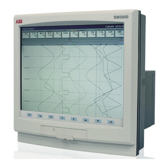
- Page 1 Inform User Guide IM/SM3000 Multipoint Videographic Recorder SM3000...
- Page 2 We are an established world force in the design and manufacture of instrumentation for industrial process control, flow measurement, gas and liquid analysis and environmental applications. Cert. No. Q05907 As a part of ABB, a world leader in process automation technology, we offer customers application expertise, service and support worldwide. EN 29001 (ISO 9001) We are committed to teamwork, high quality manufacturing, advanced technology and unrivalled service and support.
-
Page 3: Table Of Contents
CONTENTS 1 INTRODUCTION .............. 2 5 INSTALLATION .............. 86 Siting ................86 2 OPERATION ..............3 Mounting ................. 87 Powering Up the Instrument ..........3 Electrical Connections ............. 88 Analog Inputs ..............90 Displays and Controls ............3 Chart Views ............... 5 5.4.1 Current and Voltage .......... -
Page 4: Introduction
1 INTRODUCTION Functional Overview – Fig. 1.1. • 36 Recording Channels as standard, equally divided into up • Any source can be assigned to any recording channel. to 6 Process Groups, each with up to a maximum of 12 • Data from assigned sources can be displayed in: Recording Channels. -
Page 5: Operation
2 OPERATION 2.1 Powering Up the Instrument When power is first applied to the instrument, its processor carries out a number of self-tests and displays the start-up screen. At the end of the start up sequence the instrument displays the last Operator View that was displayed when the instrument was powered down. - Page 6 …2 OPERATION …2.2 Displays and Controls – Figs. 2.1 and 2.2 Process Group 1 Process Group 5 Process Group 2 Process Group 6 Process Group 3 Instrument Status & Logs Process Group 4 Note. Only process groups and views that have been enabled are displayed –...
-
Page 7: Chart Views
2 OPERATION… 2.3 Chart Views (Horizontal and Vertical – Fig. 2.3) Group Tag Status Bar Status Icon Digital On/Off Tag Units Short Channel Tag Current Date and Time Current Value (see on Page 7) Note 1 Scale Bar Newest Data 15:07:39 High Out Flow Rate Chart Trace Time Stamp... - Page 8 …2 OPERATION …2.3 Chart Views (Circular – Fig. 2.4) Operator Message Alarm Event Icon (see on Page 7) Note 2 (appears for 1 second) Global Alarm Group Tag Status Bar Status Icon Status Icon Current Date and Time Units Short Channel Current Value Time Stamp (see...
- Page 9 2 OPERATION… …2.3 Chart Views Notes. 1. Current Values The Current Value, shown on the digital indicators at either the top (vertical chart view) or right hand side (horizontal chart view) of the screen, is the latest instantaneous value and its update rate is not affected by the recording sample rate. If the current value in the digital indicator is displayed in red, recording has been stopped for that channel –...
- Page 10 …2 OPERATION …2.3 Chart Views Notes. While in Historical Review mode: • Recording of new data continues unless stopped from the Setup Menu – see Section 3.4. • Invalid historical data (e.g. when recording has stopped) is denoted by '– – –' in the digital indicator.
- Page 11 2 OPERATION… …2.3 Chart Views Add one of 24 predefined Operator Messages (see Section 4.4.4) or one User-Defined Operator Messages Message to the alarm event log. If '<user defined>' is selected, a data entry keyboard 1 - 6 Start of batch appears to enable the message to be entered –...
- Page 12 …2 OPERATION …2.3 Chart Views Note. Applicable only to Vertical and Horizontal Chart views. Screen Interval Use the 'Screen Interval' to change the amount of data displayed on the screen. A longer 48 seconds/screen screen interval displays more data, a shorter screen interval displays data over a shorter 4 minutes/screen time period, but in more detail.
- Page 13 2 OPERATION… …2.3 Chart Views Note. Applicable only to Vertical and Horizontal Chart views. Scales Select the scale(s) to be displayed in the scale bar at the top of the chart window. For digital channels, the On and Off tags are displayed at the corresponding position on the scale bar. A maximum of 3 scales can be selected for display at any one time.
- Page 14 …2 OPERATION …2.3 Chart Views Note. Applicable only to Circular Chart view. Totalizer Stop/Go ch1.1 Volume Stop and start individual totalizers. ch1.2 Pressure ch1.3 In Flow Channel totalizers that have not been enabled in the Configuration level are greyed-out. A: Total Flow 1.3A ch1.4 Volume B: Total Flow 1.3B ch1.5 Valve...
-
Page 15: Electronic Signatures
2 OPERATION… 2.3.1 Electronic Signatures – Fig. 2.5 Entering an electronic signature is the equivalent to signing the chart of a conventional paper recorder. Local procedures may require the approval of a record by an authorized signatory; for this reason, an electronic signature is password protected. Invalid Password Entered (see... -
Page 16: Bargraph Views
…2 OPERATION 2.4 Bargraph Views – Fig. 2.6 Operator Message (appears for 1 second) Status Bar Status Icon Alarm Event Icon Short Channel Tag Digital On or Off tag, Current Value according to input status Engineering Units Engineering Range High Value Alarm Trip Level (not shown for slow and fast rate alarms) - Page 17 2 OPERATION… …2.4 Bargraph Views Select the Configuration level – See Section 4. Configuration Select the Setup level – see Section 3. Setup Add one of 24 predefined Operator Messages (see Section 4.4.4) or one User-Defined Operator Messages Message to the alarm event log. If '<user defined>' is selected, a data entry box appears 1 - 6 to enable the message to be entered –...
-
Page 18: Digital Indicator View
…2 OPERATION 2.5 Digital Indicator View – Fig. 2.7 Alarm Event Icon Global Alarm Status Icon Status Bar Status Icons Short Channel Tag Current Value Engineering Units Alarm Indication (Flashing red border and alarm event icon indicates alarm unacknowledged. Continuous alarm event icon indicates alarm acknowledged) Channel Units Totalizer Units... - Page 19 2 OPERATION… …2.5 Digital Indicator View Select the Configuration level – see Section 4. Configuration Select the Setup level – see Section 3. Setup Add one of 24 predefined Operator Messages (see Section 4.4.4) or one User-Defined Operator Messages Message to the alarm event log. If '<user defined>' is selected, a data entry box appears 1 - 6 to enable the message to be entered –...
- Page 20 …2 OPERATION …2.5 Digital Indicator View Channel Select Display all configured channel indicators for the process group currently selected for Channel Select display. Show All Channels for Group 1 Show All Configured Channels Display all configured channel indicators for all process groups. Channel Select Show All Channels for Group 1 Note.
-
Page 21: Process View
2 OPERATION… 2.6 Process View – Fig. 2.8 Alarm Tag Alarm Trip Level Instantaneous Value Global Alarm Status Icon Alarm Event Icon (Alarm Inactive) Long Channel Tag (Short Channel Tag) Totalizer Tag Name Totalizer Value Alarm Event Icon (Alarm Active) Alarm Acknowledged Icon Min Average... - Page 22 …2 OPERATION …2.6 Process View Select the Configuration level – see Section 4. Configuration Select the Setup level – see Section 3. Setup Operator Messages Add one of 24 predefined Operator Messages (see Section 4.4.4) or one User-Defined 1 - 6 Message to the alarm event log.
-
Page 23: Instrument Status / Audit Log View
2 OPERATION… 2.7 Instrument Status / Audit Log View – Fig. 2.9 otes. • The combined Instrument Status and Audit log view provides an overview of the instrument's status together with an historical log of system activity. • The two views are described separately in Sections 2.7.1 and 2.7.2. Instrument Status –... -
Page 24: Instrument Status View
…2 OPERATION 2.7.1 Instrument Status View – Fig. 2.10 Note. The Instrument Status view provides an overview of the instrument's status. Instrument Software Version Operating System Version Instrument Serial Number Instrument Tag Modules fitted to the instrument Amount of memory used on the archive media currently installed Cold junction temperatures... -
Page 25: Audit Log View
2 OPERATION… 2.7.2 Audit Log View – Fig. 2.11 otes. • The Audit log view provides an historical log of system activity. • When the number of entries in the Audit log has reached that defined in 'Audit log size' (see Section 4.4.3), the oldest data is overwritten by the newest. -
Page 26: Alarm Event Log
…2 OPERATION 2.8 Alarm Event Log – Fig. 2.12 ote. The Alarm Event log view provides an historical log of all alarm events in the sequence in which they occurred. To view the current status of all alarms, choose the Process View – see Section 2.6. Short tag of the alarm's source Global Alarm Status Icon View previous... - Page 27 2 OPERATION… …2.8 Alarm Event Log Select the Configuration level – see Section 4. Configuration Select the Setup level – see Section 3. Setup Select the entries to be displayed in the log. Indicates entries currently displayed. Filter Notes. Group 1 Alarms •...
-
Page 28: Totalizer Log
…2 OPERATION 2.9 Totalizer Log – Fig. 2.13 otes. • The Totalizer log view provides an historical log of totalizer activity. To view the current totalizer status, choose the Process or Digital View. • When the number of entries in the Totalizer log has reached that defined in 'Totalizer log size' (see Section 4.4.3), the oldest data is overwritten by the newest. - Page 29 2 OPERATION …2.9 Totalizer Log Select the Configuration level – see Section 4. Configuration Select the Setup level – see Section 3. Setup Select the log entries to be displayed. indicates entries selected for display. Filter Notes. Group 1 Totalizers •...
-
Page 30: Setup
3 SETUP 3.1 Introduction ote. Users with Setup access can: • Start/Stop recording. • Switch between primary and secondary recording rates. • Set archiving 'on-line' and 'off-line'. • View internal and external archive media file directories and delete external archive media files. 3.2 Accessing the Setup Level –... -
Page 31: Password Entry
3 SETUP… 3.3 Password Entry Enter Password 1) Select the required character using the , and keys. 2) Add the selected character to the password string using the key. Note. For security, all characters are displayed as ' '. 3) Repeat 1 and 2 until all characters have been entered. 4) Highlight the 'OK' button using the , and keys and press... -
Page 32: Setup Menu
…3 SETUP 3.4 Setup Menu Use this menu to stop and start recording or change the sample rate for the channels in the Recording Control current Process Group. Stop The Primary sample rate is set typically to a relatively slow rate (depending upon process Primary recording requirements) and is active during normal process operating conditions in order Secondary... - Page 33 Note. Files stored in internal memory cannot be deleted. The diagnostics features are available only on instruments with the Advanced Software Diagnostics option enabled. To use the diagnostics features, refer to the Advanced Software Options Maths Supplementary Manual, IM/SM3000–ADV. Logic...
-
Page 34: Archiving
…3 SETUP 3.5 Archiving Recorded data, logs and configuration files stored on the instrument's internal memory can be archived to files created on removable media. Parameters for archiving each process groups' data are configured independently. Note. To configure Archiving, refer to Section 4.5.6. 3.5.1 SmartMedia Handling and Care Note. -
Page 35: Inserting And Removing Media
3 SETUP… 3.5.3 Inserting and Removing Media – Fig. 3.3 Note. When inserting the media into the instrument: Set the archive media off-line – • Ensure the media is the correct type for the instrument. see Section 3.4 • If SmartMedia option is fitted, ensure only 3.3V SmartMedia cards used. -
Page 36: Archive File Types
…3 SETUP 3.5.4 Archive File Types 3.5.6 Channel Data Files Archive files created by the instrument are given filenames A new channel data file is created under the following conditions: automatically. Each type of archived file is given a different •... -
Page 37: Log Files
3 SETUP… 3.5.7 Log files 3.5.9 Data Verification and Integrity A new log file is created under the following conditions: When data is saved to the archive media it is checked automatically to verify that the data stored on the media matches •... -
Page 38: File Formats
…3 SETUP 3.5.11 File Formats – Figs. 3.4 to 3.7 The archived data is stored in a secure binary encoded format. A separate file is created for each recoding channel. The log data is stored in an encrypted text format. The files can be read on a PC using the Company's DataManager data analysis software package. Note. - Page 39 3 SETUP Fig. 3.5 Alarm Event Log Sample Fig. 3.6 Totalizer Log Sample Fig. 3.7 Audit Log Sample...
-
Page 40: Configuration
4 CONFIGURATION 4.1 Introduction This section details the configuration of the instrument locally using the front panel membrane switches. A configuration file can also be created on a PC and transferred to the instrument via one of the archive media options. In addition, up to 5 different configurations can be stored in internal memory and restored when required. - Page 41 4 CONFIGURATION… …4.1.2 Configuration Access – Figs. 4.1 and 4.2 Invalid Password Entered (see Note in Fig. 3.1 on page 28) Configuration Configuration Level Operator 1 Protected (see Section 4.1.1) Operator 2 Operator 3 Operator 14 Valid Password Configuration Level Operator 15 Entered Unprotected...
- Page 42 …4 CONFIGURATION …4.1.2 Configuration Access – Figs. 4.1 and 4.2 Note. The Internal Security Switch is used to access the Configuration level when 'Configuration security type' is set to 'Internal switch protected' – see Section 4.4.2. use the switch to access the Configuration level when Do Not 'Configuration security type' is set to 'Password protected' (default setting) unless the Password has been forgotten.
-
Page 43: Overview Of Configuration
4 CONFIGURATION… 4.2 Overview of Configuration – Fig. 4.3 Select the required parameter using the keys. Press the key to edit selected parameter. Select 'Common' from the Configuration menu Use the keys to select the next required tab Press the key to display the menu. -
Page 44: Making Changes To Parameters
…4 CONFIGURATION 4.3 Making Changes to Parameters – Figs. 4.4 to 4.7 Configuration Tab Edit Button Parameter Copy Window Parameter Value Parameter Selection Window – Note 1 below Use the key to advance Use the keys to to the next channel and the highlight a different selection. - Page 45 4 CONFIGURATION… …4.3 Making Changes to Parameters – Figs. 4.4 to 4.7 keys to highlight an item and press to select it. Note. Items not selected are indicated by an X in the parameter value window. 1 2 3 4 X X X X X X X X Highlight text box and use keys to position cursor to edit text as required.
- Page 46 …4 CONFIGURATION …4.3 Making Changes to Parameters – Figs. 4.4 to 4.7 Select the tab appropriate to the data to be copied. Press the key to open the menu and use the keys to select the copy facility. Source of copied data Use the keys to select copy destinations.
- Page 47 4 CONFIGURATION… …4.3 Making Changes to Parameters – Figs. 4.4 to 4.7 e t l i r a z i r s t i c i r c i r n i r n i r o i t n i r s t i o i t e t l...
- Page 48 …4 CONFIGURATION …4.3 Making Changes to Parameters – Figs. 4.4 to 4.7 n i t r a l l l A r a l r a l y l i – o i t – – t l i f o i t –...
- Page 49 4 CONFIGURATION… …4.3 Making Changes to Parameters – Figs. 4.4 to 4.7 Notes. • The current, active, configuration is saved to internal storage with the filename 'SM3000.cfg'. • Selecting 'Save as Current Configuration' suspends recording for a short time while the new configuration is implemented.
-
Page 50: Common Configuration
…4 CONFIGURATION 4.4 Common Configuration Fig. 4.8 Selecting Common Configuration 4.4.1 Setup Configuration type is fixed as 'Basic'. Enter the number of process groups required. The number of channels assigned to each process group is dependent upon the number of groups selected – see Table 4.2 below. - Page 51 4 CONFIGURATION… ...4.4.1 Setup Set the current date and time. Note. If daylight saving is required, enter the settings (see next page) setting the time and date as the operation before of the internal clock is affected by the daylight saving settings.
- Page 52 …4 CONFIGURATION ...4.4.1 Setup Select the daylight saving method. Note. Changes to daylight saving are effective immediately a method is selected. However, if 'Cancel' is selected upon exiting Configuration Mode (see Fig. 4.7, page 47), the last saved daylight saving settings are restored. g i l g i l c i t...
-
Page 53: Security
4 CONFIGURATION… 4.4.2 Security Change user names, access privileges and passwords. Notes. • User 1 is the System Administrator and is able to change user names/access privileges and enter initial passwords for all users. Other users cannot change their user names and access privileges once set by User 1. All users may change their own passwords. - Page 54 …4 CONFIGURATION …4.4.2 Security Enter the number of consecutive incorrect password entries allowed by a user. If the number of incorrect entries exceeds this limit, the user's access privileges are de-activated and can be reinstated only by the System Administrator (User 1). Passwords have a maximum length of 20 characters.
-
Page 55: Logs
4 CONFIGURATION… 4.4.3 Logs Set the maximum number of entries in each instrument log. Note. Changing the log size deletes the current log entries. records all process alarm transitions Alarm Event log (inactive to active, unacknowledged to acknowledged or active to inactive), real-time events and Operator Messages –... -
Page 56: Ethernet
…4 CONFIGURATION 4.4.5 Ethernet The Ethernet module fitted to the instrument contains an embedded web server enabling the instrument's data and status to be viewed remotely using an internet browser on a PC. The web server supports up to eight independant connections. Notes. -
Page 57: E-Mail
4 CONFIGURATION… 4.4.6 e-mail The instrument can be configured to send e-mails to a maximum of 6 recipients in response to certain events. The addressees can all subscribe to the same SMTP server or the instrument can be configured to send e-mails via 2 different SMTP servers to a maximum of 3 addressees per server. - Page 58 …4 CONFIGURATION …4.4.6 e-mail Enter the IP address of the SMTP server through which e-mails are to be routed. Enter the address(es) of the e-mail recipient(s). Select the options to enable: Channels Report A summary of all enabled channels is included in the e-mail, together with their instantaneous values.
-
Page 59: Process Group Configuration
4 CONFIGURATION… 4.5 Process Group Configuration Process Group 1 Process Group 2 Process Group 3 (see Note below) Note. The number of Process Groups and associated channel options displayed depend on the number of Process Groups selected during common configuration setup – see Section 4.4.1. Fig. - Page 60 …4 CONFIGURATION ...4.5.1 Setting the Recording Parameters The instrument can be configured to sample all recording channels in the group and store the data in internal memory and external archive media (if archiving is enabled) at two rates, Primary and Secondary. The Primary sample rate is active during normal process operating conditions and is set typically to a relatively slow rate (depending upon process recording requirements) in order to maximize internal memory and external archive media capacity.
-
Page 61: Configuring The Chart View
4 CONFIGURATION… 4.5.2 Configuring the Chart View Major Chart Divisions Minor Chart Divisions Scale Bar Time Stamp Chart Trace Chart Divisions Screen Interval Operator Message Annotation Alarm Event Annotation Screen Interval Select Horizontal, Vertical or Circular chart view. Select the annotations to be displayed on the chart. Alarm events and operator messages are displayed on the chart adjacent to the point at which the alarm occurred –... - Page 62 …4 CONFIGURATION …4.5.2 Configuring the Chart View Select the amount of historical data to be displayed on the screen. Available selections are limited by the sample rate Vertical and Horizontal Chart Views only selected – see Page 58 and Table 2.1 on page 10. Circular Chart View only Select the required trace width in pixels (Vertical and Horizontal Chart views only).
-
Page 63: Configuring The Bargraph View
4 CONFIGURATION… 4.5.3 Configuring the Bargraph View Engineering Range High Value Alarm Trip Level (not shown for slow and fast rate alarms) Maximum Value (solid color) Engineering Range Middle Value Instantaneous Value Minimum Value (white fill) Engineering Range Low Value Analog Channels Digital Channel... -
Page 64: Configuring The Process View
…4 CONFIGURATION 4.5.4 Configuring the Process View Alarm Alarm Trip Channel Long Tag Name (Short Tag Name) Level Totalizer Tag Totalizer Average Name Value Values since last Totalizer Reset or Totalizer wrap. Updated only if the Totalizer is Enabled and Running. Set to 'On' to enable the operator to display the Process view. -
Page 65: Configuring The Digital Indicator View
4 CONFIGURATION… 4.5.5 Configuring the Digital Indicator View Short Channel Tag Channel Units Current Value Totalizer Units – see below Note Units Totalizer Value – see below Note ote. Displayed only if the totalizer is enabled for that channel (see Section 4.6.5) Alarm Status display (see below). - Page 66 …4 CONFIGURATION …4.5.5 Configuring the Digital Indicator View Select the channels to be accessible from the Digital Indicator view. Note. Channels that are not enabled are greyed-out in the Digital Indicator view menu.
-
Page 67: Archiving
4 CONFIGURATION… 4.5.6 Archiving Introduction Recorded data, logs and configuration files stored in the instrument's internal memory can be archived to files created in removable media. Parameters for archiving data in each process group are set up independantly. For a full description of archiving and archive file formats, refer to Section 3.5. Sample Rates –... -
Page 68: Channel Configuration
…4 CONFIGURATION 4.6 Channel Configuration Process Group 1, Channels 1.1 to 1.12 Note. The number of Process Groups and associated channel options displayed depend on the number of Process Groups selected during common configuration setup – see Section 4.4.1. Fig. 4.13 Recording Channel Configuration... -
Page 69: Recording Channel Setup
4 CONFIGURATION… 4.6.1 Recording Channel Setup •1 Select the signal source for the selected channel. This can be any external analog or digital signal – see APPENDIX 1 for full list. Note. The tabs change according to the selection made. A –... - Page 70 …4 CONFIGURATION …4.6.1 Recording Channel Setup Select the filter to be applied to the electrical input prior to •1 sampling. Notes. • Applicable to analog sources only. • Filters are applied to the recorded values shown on the chart view only, not to instantaneous values displayed on the channel indicators or bargraphs.
-
Page 71: Analog Input Configuration
4 CONFIGURATION… 4.6.2 Analog Input Configuration Notes. • The 'Analog I/P' tab is displayed only if 'Source ID' for the Recording Channel is set to an analog signal source – see Section 4.6.1. • If an analog input is assigned to more than one recording channel, changes to any of its parameters and tags are applied to each channel the input is assigned to. - Page 72 …4 CONFIGURATION …4.6.2 Analog Input Configuration Specify the display range and units of the engineering value corresponding to the electrical high and low values, within the limits defined in the following table: °C °F THC/RTD Type Min. Max. Min. Max. Type B –18 1800...
-
Page 73: Digital Input Configuration
4 CONFIGURATION… …4.6.2 Analog Input Configuration Set the time period over which the process variable is to be filtered prior to being sampled (0 to 60 seconds). Set a tolerance level (between 0 and 100% of the engineering range) to allow for deviation of the input signal above or below the input span before an input failure is detected. -
Page 74: Alarm Configuration
…4 CONFIGURATION 4.6.4 Alarm Configuration Hysteresis Trip Point Hysteresis Process Variable Alarm On High Process Alarm Off Alarm On Low Process Alarm Off Fig. 4.14 High/Low Process Alarms Trip Point Hysteresis Process Variable Alarm On Alarm Latched Alarm Off Alarm acknowledged by operator High Latch Alarm Action Process... - Page 75 4 CONFIGURATION… …4.6.4 Alarm Configuration Process Variable Trip Point Hysteresis Hysteresis Trip Point Process Variable Alarm On Alarm On Alarm Off Alarm Off Alarm acknowledged Alarm acknowledged by operator by operator High Annunciate Alarm Action Low Annunciate Alarm Action Fig. 4.16 High/Low Annunciate Alarms Deviation exceeded –...
- Page 76 …4 CONFIGURATION …4.6.4 Alarm Configuration Process variable goes Process variable goes Process variable goes above trip point but above trip point but Process variable goes above trip point, alarm is alarm is not activated alarm is not activated below trip (hysteresis) activated (alarm is because enable signal because alarm delay...
- Page 77 4 CONFIGURATION… …4.6.4 Alarm Configuration ote. The Alarm Configuration tabs are displayed only if 'Source ID' for the Recording Channel is set to an analog signal source – see Section 4.6.1. Set the alarm type: High/Low process – see Fig. 4.14 High/Low latch –...
- Page 78 …4 CONFIGURATION …4.6.4 Alarm Configuration Set the minimum or maximum amount of deviation allowed within the alarm 'Period' (see below) before the alarm is activated. Note. Rate alarms only – see Fig. 4.17. Set the time period over which the deviation is measured. For fast rate alarms, the alarm becomes active if the value changes by more than the devation value within the alarm period.
-
Page 79: Totalizer Configuration
4 CONFIGURATION… 4.6.5 Totalizer Configuration Notes. • Current totalizer values are displayed in the Digital Indicator, Process and Circular Chart Views – see Sections 2.3, 2.5 and 2.6 (Operation), and Sections 4.5.2, 4.5.4 and 4.5.5 (Configuration). • For analog sources, the total value of a signal is calculated by counting pulses produced at a rate proportional to the input. For digital sources, off/on transitions are counted and scaled to produce a batch total. - Page 80 …4 CONFIGURATION …4.6.5 Totalizer Configuration Set the value the totalizer counts from and the value applied when the totalizer is reset. Set the value at which the totalizer stops or wraps. Note. A counter configured to count up must have a 'Preset count' value lower than the 'Predetermined count' value.
- Page 81 4 CONFIGURATION… …4.6.5 Totalizer Configuration Set the required totalizer count rate. The count rate is determined by the maximum number of Analog Input Sources only – see Section 4.6.1 engineering units (or pulses) per second and the smallest totalizer increment: engineering full scale value (rate) engineering units (in seconds) –...
-
Page 82: I/O Module Configuration
…4 CONFIGURATION 4.7 I/O Module Configuration Note. The instrument detects the type of module fitted in each position automatically. Fig. 4.19 I/O Module Configuration 4.7.1 Analog Inputs Set the mains rejection frequency used to filter electrical noise induced on the signal lines by power supply cables. Input Adjustment Manually fine-tune inputs to remove process offset errors or system scale errors. -
Page 83: Relay Modules
4 CONFIGURATION… …4.7.1 Analog Inputs Offset adjust / Span adjust Manually fine-tune the offset adjust and span adjust values to remove process errors. These are calculated values applied to the raw input signal. Note. If simulating thermocouple inputs, connect the millivolt source using appropriate compensating cable –... -
Page 84: Hybrid Modules
…4 CONFIGURATION 4.7.3 Hybrid Modules Select a digital output source. Notes. • A digital output source is the internal digital source used to activate/de-activate a digital output. • If a digital output is used to provide a totalizer count pulse, the maximum pulse frequency is 5Hz. -
Page 85: Rs485 (Modbus) Modules
4 CONFIGURATION… …4.7.3 Hybrid Modules Select the analog output source. Note. The analog output source can be any internal or external analog signal. Set the required analog output engineering range. Note. The 'Engineering low' and 'Engineering high' settings are the engineering values corresponding to the 'Electrical low' and 'Electrical high' values below. -
Page 86: Functions
…4 CONFIGURATION 4.8 Functions Fig. 4.20 Functions Configuration 4.8.1 Custom Linearizers Use the keys to highlight the linearizer to be adjusted. Use the key to open the 'Adjust custom linearizer' screen. Use the keys to highlight the point to be modified. Press the key to open the digipad to change the position of the point. -
Page 87: Real-Time Alarms
4 CONFIGURATION 4.8.2 Real-time Alarms Enter the tag to be used in the Alarm Event log – see Section 2.8. Set the day(s) on which the alarm is activated. Set to 'On' to activate the real-time alarm on the first day of each month. -
Page 88: Installation
5 INSTALLATION EC Directive 89/336/EEC In order to meet the requirements of EC Directive 50°C 89/336/EEC for EMC regulations, this product must not (122°F) Max. be used in a non-industrial environment. 0°C (32°F) Min. End of Life Disposal A – Within Temperature Limits •... -
Page 89: Mounting
5 INSTALLATION… 5.2 Mounting – Figs. 5.3 and 5.4 Dimensions in mm (in.) 9 (0.35) Gasket 26 (1.02) + 0.04 (11.06 288 (11.34) – 0 – 0 168 (6.61) Panel Cut-out 14 (0.55) Minimum 30 (1.18) 38 (1.50) Gasket Between Cut-outs 4 (0.16) Fig. -
Page 90: Electrical Connections
…5 INSTALLATION 5.3 Electrical Connections – Fig 5.5 Warnings. • The instrument is not fitted with a switch therefore a disconnecting device such as a switch or circuit breaker conforming to local safety standards must be fitted to the final installation. It must be fitted in close proximity to the instrument within easy reach of the operator and must be marked clearly as the disconnection device for the instrument. - Page 91 5 INSTALLATION… …5.3 Electrical Connections – Fig 5.5 Module Positions AC Power Supply Earth (Ground) Stud – see on page 88 Warnings Continuity/ External Voltage Divider – Receive LED on page 90 Warnings Transmit Ethernet – RJ45 Connector A, B, C, D, E, F E, F, G, H G, H Transmitter...
-
Page 92: Analog Inputs
…5 INSTALLATION 5.4 Analog Inputs 5.4.1 Current and Voltage – Fig. 5.6 – – – Warnings. 10Ω Resistor supplied Voltage divider • When input 'Type' is set to 'Volts' (see in accessory pack. (GR2000/0375) Section 4.6.2), inputs be connected must required for through an external voltage divider (part no. -
Page 93: Mains Power Connections
5 INSTALLATION… 5.5 Mains Power Connections – Fig 5.8 5.6 Relay Output Board Connections – Fig. 5.9 Fuse, Notes. 400mA, Type T • The maximum total combined current flowing Line through the relays is 36A. The maximum individual 85 min. to 265V max. Neutral relay current is 5A. -
Page 94: Hybrid I/O Module Connections
…5 INSTALLATION 5.7 Hybrid I/O Module Connections 5.7.3 Analog Output Connections – Fig 5.12 5.7.1 Digital Output Connections – Fig 5.10 Two analog outputs are provided on the Hybrid option board. Six digital outputs are provided on the Hybrid option board. –... -
Page 95: Ethernet Network Connections
5 INSTALLATION… 5.8 Ethernet Network Connections 5.8.1 Direct Connection to a Computer – Figs. 5.13 and 5.14 Note. Ensure that permission has been granted for installation of new devices on the network. If in doubt, Note. A crossover cable required this consult the System Administrator before connecting configuration. -
Page 96: Connection To A Network Hub
…5 INSTALLATION 5.8.2 Connection to a Network Hub – Fig. 5.15 Fig. 5.15 Connection to a Network Hub 5.8.3 Connection to a Dial-Up Router – Fig. 5.16 Router Router WAN / Internet Fig. 5.16 Connection to a Dial-Up Router 5.8.4 Connection to an Internet Gateway – Fig. 5.17 Internet Gateway Fig. -
Page 97: Appendix 1 - Signal Sources
APPENDIX 1 – SIGNAL SOURCES o i t t i f o i t a t i t i f . ) e a l i o i t t i f o i t a t i t l o i g i l a t –... -
Page 98: Appendix 2 - Storage Capacity
APPENDIX 2 – STORAGE CAPACITY A2.1 Internal Storage Capacity Table A2.1 Internal Storage Capacity... -
Page 99: A2.2 Archive Storage Capacity
APPENDIX 2 – STORAGE CAPACITY A2.2 Archive Storage Capacity Note. The times shown are for archiving of a single group. If more than one group is archived, divide the durations by the number of groups. Table A2.2 External (Archive) Storage Capacity... -
Page 100: Appendix 3 - Default Settings
APPENDIX 3 – DEFAULT SETTINGS …A3.1.2 Process Groups 1 to 6 A3.1 Company Standard A3.1.1 Common Configuration Chart View Chart view enable Vertical Setup Chart annotation None Configuration type Basic Major chart divisions Number of groups Minor chart divisions Time format hhmmss Screen interval 8 minutes/screen... -
Page 101: A3.1.3 Recording Channels
APPENDIX 3 – DEFAULT SETTINGS… A3.1.3 Recording Channels …A3.1.3 Recording Channels Setup Totalizers Source indentifiers Count enable Channels 1.1 to 1.6 Analog I/P A1 to A6 Wrap enable Wrap on All other channels None Channel x.xA totalizer tag Total flow x.xA Trace color Channel x.xB totalizer tag Total flow x.xB... -
Page 102: A3.1.5 Functions
…APPENDIX 3 – DEFAULT SETTINGS A3.1.5 Functions A3.2 QuickStart Templates Custom Linearizers 1, 2, 3 and 4 A3.2.1 QSMilliAmp X co-ordinates 0.0, 5.0, 10.0, 15.0, Bargraph 20.0, 25.0, 30.0, 35.0, Bar graph view enable Vertical 40.0, 45.0, 50.0, 55.0, Bar graph markers Max and min 60.0, 65.0, 70.0, 75.0, Menu enables... -
Page 103: A3.2.5 Qsrtd_C
APPENDIX 3 – DEFAULT SETTINGS A3.2.5 QSRTD_C …A3.2.7 QSDEMO As A3.2.3 QSTHC_C, except: Analog inputs Analog inputs Type Simulated sinewave Type Resistance thermometer Engineering low Linearizer type PT100 Engineering high 10.0 Engineering Units Ch1.1 °C A3.2.6 QSRTD_F Ch1.2 Ch1.3 Gal/h As A3.2.3 QSTHC_F, except: Ch1.4 Litres... -
Page 104: Appendix 4 - Ethernet
APPENDIX 4 – ETHERNET A4.1 Introduction Other protocols that operate at the same level are the Address A4.1.1 Ethernet Communications Resolution Protocol (ARP) and the Internet Control Message Ethernet is a form of electronic communication that has been Protocol (ICMP). adopted as a worldwide networking standard. -
Page 105: A4.2 Testing A Network Connection
To obtain the FTSP and its user guide, send an e-mail to ftp.scheduler@gb.abb.com with 'download' in the subject line. Fig. A4.3 DOS Window 3) Type 'ping' followed by the IP address assigned to the instrument and press Enter. - Page 106 APPENDIX 4 – ETHERNET… A4.3.1 FTP Access via MS-DOS The following FTP commands are used to communicate with the To use FTP access: instrument: 1) If the DOS window is not open, click the 'Start' button on the Change directory on the server task bar and select 'Run'.
- Page 107 …APPENDIX 4 – ETHERNET A4.3.2 FTP Access via Internet Explorer 3) Enter the 'User Name:' and 'Password:' for the instrument (see Section 4.4.5), and click on 'Login'. The contents of the instrument, that looks similar to the following, is displayed: Note.
- Page 108 APPENDIX 4 – ETHERNET… …A4.3.2 FTP Access via Internet Explorer A4.3.3 Using FTP Access with DataManager 7) Select the 'Copy To Folder' option. The 'Browse for Folder' The Company's DataManager software can be used with FTP to window is displayed: access data files that have been saved to the archive media (SmartMedia or Compact Flash card) inserted in the instrument.
-
Page 109: A4.4 Using The Instrument's Web Server
…APPENDIX 4 – ETHERNET A4.4 Using the Instrument's Web Server – Figs A4.8 to A4.17 Figs. A4.8 to A4.17 are examples of the page views available from the instrument's web server. Instrument's Click on the relevant IP address hyperlink to display the entire log in the browser window Instrument tag... - Page 110 APPENDIX 4 – ETHERNET… …A4.4 Using the Instrument's Web Server – Figs A4.8 to A4.17 Latest value of channel Alarm status of each channel – refer to rear foldout Channel tags and units of measure for identification of alarm icons Primary and If enabled, the secondary...
- Page 111 …APPENDIX 4 – ETHERNET …A4.4 Using the Instrument's Web Server – Figs A4.8 to A4.17 Totalizer preset Current secure total predetermined values Current batch total Totalizer tag Current totalizer status Configured totalizers, color coded for each channel Totalizer units of measure Fig.
- Page 112 APPENDIX 4 – ETHERNET… …A4.4 Using the Instrument's Web Server – Figs A4.8 to A4.17 Module A analog inputs Cold junction compensation reading for module A Module B analog inputs Cold junction compensation reading for module B Fig. A4.14 Analog Signals Page Current status of digital signals List of all digital...
- Page 113 …APPENDIX 4 – ETHERNET …A4.4 Using the Instrument's Web Server – Figs A4.8 to A4.17 Enter a valid FTP username – see Section 4.4.5 Enter an associated FTP password – see Section 4.4.5 Enter message to be sent to the instrument (maximum 20 characters) Click on button to send message.
-
Page 114: A4.5 Glossary Of Terms
APPENDIX 4 – ETHERNET A4.5 Glossary of Terms Open system The following terms have specific meanings within the Ethernet A system conforming to specifications and guidelines that environment: are 'open' to all. This allows any manufacturers' equipment that comply with these standards used... -
Page 115: Appendix 5 - Spare Parts & Accessories
GR2000/0704 Hybrid I/O board upgrade pack GR2000/0705 Documentation Pack Transmitter PSU board upgrade pack This manual GR2000/0706 IM/SM3000 Quick reference guide 6-Channel analog I/P board upgrade pack IM/SM3000–Q GR2000/0708 End User Licence Agreement RS485 serial communications board upgrade pack IM/SM2000–L... -
Page 116: Appendix 6 - Error & Diagnostics Information
APPENDIX 6 – ERROR & DIAGNOSTICS INFORMATION Error Message Action "The system has not finished updating the files in the storage card folder. Re-insert the storage card immediately and press the key to clear Please re-insert the storage card now. WARNING: Failure to do so may the error message. -
Page 117: Index
INDEX Accessories ............... 1 Channel Indicator Alarm Event Log ............24, 53 Tags ..............70, 71 Filter ................25 Chart Alarms ................7 Annotation ............9, 59 Acknowledging ........... 18, 25 AutoView Scroll ........12, 15, 18, 20 Event ................7 Duration ............... - Page 118 …INDEX …C …Configuration File Viewer ............... 31 Security ..............38 Filters Access Privileges ..........52 Recording Channel Input ........... 68 Inactive User De-activation ........51 Filter Time ............71 Passwords ............52 FTP Logon ..............54 Switch ............38, 40 Functions ................
- Page 119 INDEX Offset adjust ..............81 Thermocouple Compensating Cable ....... 91 Operator Messages Totalizer Log ............. 26, 53 Bargraph View ............15 Filter ................27 Chart View ..............9 Max/Min Details ............27 Digital Indicator ............17 Update Frequency ............. 78 Message Tag .............
- Page 120 NOTES...
- Page 121 – Manufacturing United Kingdom Historical Review Active – Metals and Minerals – Oil, Gas & Petrochemical ABB Limited Archive media on-line – Pulp and Paper Tel: +44 (0)1480-475-321 (green icon – shaded area indicates % used) Process Group 6 Configuration...
- Page 122 Microsoft and MS-DOS are registered trademarks of the Microsoft Corporation Modbus is a registered trademark of Modicon Lotus 1,2,3 is a registered trademark of the Lotus Development Corporation ABB has Sales & Customer Support The Company’s policy is one of continuous product expertise in over 100 countries worldwide improvement and the right is reserved to modify the information contained herein without notice.