GE Dash 3000 Operator's Manual
Patient monitor
Hide thumbs
Also See for Dash 3000:
- Specifications (8 pages) ,
- Service manual (292 pages) ,
- Service manual (282 pages)

Related Manuals for GE Dash 3000


Summary of Contents for GE Dash 3000
- Page 1 GE Healthcare Dash™ 3000/4000/5000 Patient Monitor Operator’s Manual Software version 6 Dash™ 3000/4000/5000 English 2023909-011 (cd) 2023896-071 (paper) © 2008 General Electric Company All rights reserved.
- Page 2 6.6 or later. NOTE For technical documentation purposes, the abbreviation GE is used for the legal entity name, GE Medical Systems Information Technologies. Listed below are GE Medical Systems Information Technologies trademarks used in this document. All other trademarks contained herein are the property of their respective owners.
-
Page 3: Table Of Contents
Contents Introduction ....... . 1-1 Equipment Information ......... . 1-2 Intended Use . - Page 4 Defining Control Settings ........3-8 Restoring Factory Defaults .
- Page 5 Calculations ........... 6-8 Cardiac Calculations .
- Page 6 Monitoring Invasive Pressures ....9-1 Introduction ........... 9-2 Overview .
- Page 7 Monitoring ........... 11-8 Control Settings .
- Page 8 Monitoring End-Tidal CO2 ....15-1 Introduction ..........15-2 Overview .
- Page 9 Troubleshooting ..........17-6 Monitoring Bispectral Index (BIS) .
- Page 10 Non-GE Device Information ........
- Page 11 Symbols ........... . . F-8 2000966-386D Dash™...
- Page 12 Dash™ 3000/4000/5000 2000966-386D...
- Page 13 CE Marking Information Compliance The patient monitor bears CE mark CE-0459 indicating its conformity with the provisions of the Council Directive 93/42/EEC concerning medical devices and fulfills the essential requirements of Annex I of this directive. The product is in radio- interference protection class A in accordance with EN 55011.
- Page 14 The warranty does not cover damages resulting from the use of accessories and consumables from other manufacturers. GE is responsible for the effects on safety, reliability, and performance of the product, only if: assembly operations, extensions, readjustments, modifications, or repairs are carried out by persons authorized by GE;...
-
Page 15: Introduction
Introduction 2000966-386D Dash™ 3000/4000/5000... -
Page 16: Equipment Information
Introduction Equipment Information Intended Use The Dash™ 3000/4000/5000 patient monitor is intended for use under the direct supervision of a licensed healthcare practitioner. The intended use of the system is to monitor physiologic parameter data on adult, pediatric and neonatal patients. The Dash™... - Page 17 Introduction WARNING ACCIDENTAL SPILLS —To avoid electric shock or device malfunction, liquids must not be allowed to enter the device. If liquids have entered a device, take it out of service and have it checked by a service technician before it is used again. WARNING ACCURACY—If the accuracy of any value viewed on the monitor, central station, or printed on a graph strip is questionable, determine...
- Page 18 Introduction WARNING CONDUCTIVE CONNECTIONS—Extreme care must be exercised when applying medical electrical equipment. Many parts of the human/machine circuit are conductive, such as the patient, connectors, electrodes, transducers. It is very important that these conductive parts do not come into contact with other grounded, conductive parts when connected to the isolated patient input of the device.
- Page 19 Introduction WARNING WIRELESS COMMUNICATION INTERFERENCE—Wireless LAN equipment contains an intentional RF radiator that has the potential of interfering with other medical equipment, including patient implanted devices. Before installation and any time new medical equipment is added to the Wireless LAN coverage area, complete the following tests: Software version 5.3 or earlier —...
- Page 20 Introduction WARNING LEAKAGE CURRENT TEST—When interfacing with other equipment, a test for leakage current must be performed by qualified biomedical engineering personnel before using with patients. WARNING PATIENT AMBULATION —A patient must be assisted if ambulating with a roll-stand mounted monitor. WARNING POWER SUPPLY—The device must be connected to a properly installed power outlet with protective earth contacts only.
- Page 21 The following caution statements apply to this monitoring system: CAUTION ACCESSORIES (SUPPLIES)— To ensure patient safety, use only parts and accessories manufactured or recommended by GE. Parts and accessories used must meet the requirements of the applicable EN 60601 series safety standards and essential...
- Page 22 Introduction CAUTION ACCESSORIES (EQUIPMENT)—The use of ACCESSORY equipment not complying with the equivalent safety requirements of this equipment may lead to a reduced level of safety of the resulting system. Consideration relating to the choice shall include: use of the accessory in the PATIENT VICINITY; and evidence that the safety certification of the ACCESSORY has been performed in accordance to the appropriate EN 60601-1 and/or EN 60601-1-1 harmonized national standard.
- Page 23 ECG signal. CAUTION Changes or modifications to this device/system not expressly approved by GE may cause EMC issues with this or other equipment. This device/system is designed and tested to comply with applicable standards and regulations regarding EMC and needs to be installed and...
- Page 24 Introduction The use of accessories, transducers and cables other than those specified may result in increased emissions or decreased immunity performance of the device/system. This device/system is suitable for use in all establishments other than domestic and those directly connected to the public low-voltage power supply network that supplies buildings used for domestic purposes.
- Page 25 MPSO as it will increase the chance of the single protective earth conductor interruption. CAUTION NEGLIGENCE—GE does not assume responsibility for damage to the equipment caused by improperly vented cabinets, improper or faulty power, or insufficient wall strength to support equipment mounted on such walls.
- Page 26 Connect the power cord supplied with the monitor. Use only the original cord or an equivalent one. For measurements in or near the heart, GE recommends connecting the monitor to the equipotential stud. Use the green and yellow potential equalization cable and connect it to the equipotential stud on the back of the monitor.
-
Page 27: Equipment Symbols
NOTE The rating of protection against electric shock (indicated by symbol for CF or BF) is achieved only when used with patient applied parts recommended by GE. TYPE B APPLIED PART: Non-isolated applied part suitable for intentional external and internal application to the patient excluding direct cardiac application. - Page 28 Introduction Power Indicates where to press to open the writer door. This symbol indicates that the waste of electrical and electronic equipment must not be disposed as unsorted municipal waste and must be collected separately. Please contact an authorized representative of the manufacturer for information concerning the decommissioning of your equipment.
-
Page 29: Equipment Compliance Information
Introduction The number in the symbol indicates the EFUP period in years, as explained below. Check the symbol on your equipment for its EFUP period. This symbol indicates the product contains hazardous materials in excess of the limits established by the Chinese standard SJ/T11363-2006 Requirements for Concentration Limits for Certain Hazardous Substances in Electronic Information Products. -
Page 30: Manual Information
Introduction The class of equipment — I or N/A (not applicable). The type of applied part — B, BF, CF, Not Marked or none (no applied parts). Ordinary equipment (enclosed equipment without protection against the ingress of water). Equipment not suitable for use in the presence of a flammable anesthetic mixture with air, oxygen or nitrous oxide. Underwriters Laboratories, Inc. -
Page 31: Conventions
Introduction This manual must be used in conjunction with the GE “Critical Care Monitoring Clinical Reference and Troubleshooting Guide.” This document provides clinical reference information, such as ECG electrode placement, for GE patient monitors. Conventions Equipment This manual uses the following terms to simplify common equipment names. - Page 32 All names appearing in examples and illustrations are fictitious. The use of any real person’s name is purely coincidental. Ordering Manuals A paper copy of this manual will be provided upon request. Contact your local GE representative and request the part number on the first page of the manual. Revision History Each page of this document has the document part number and revision letter at the bottom of the page.
-
Page 33: Equipment Overview
Equipment Overview 2000966-386D Dash™ 3000/4000/5000... -
Page 34: Hardware Overview
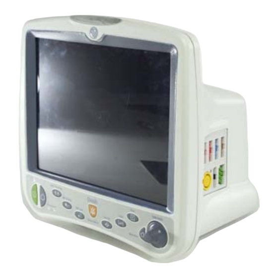
Equipment Overview Hardware Overview Front Battery Power Charging Status Graph NBP Go/Stop Zero All Trim Knob Silence Alarm/ Admit Charging Status Power Graph Go/Stop NBP Go/Stop Zero All Silence Alarm/ Admit Dash 4000 3000 4000 5000 Alarm light indicator Provides a visual alarm for patient status alarms. Control panel Provides quick function keys and the Trim Knob control to navigate menus and select options. -
Page 35: Left
Equipment Overview Patient connectors Allows patient cables to connect to the monitor. Enabled option labels Identifies the options enabled on the monitor. NOTE All patient connectors with the applied part symbol ( ) are high-insulation ports and defibrillator proof to ensure patient safety and protect the device during defibrillation and electrosurgery Left 4000... -
Page 36: Back
Equipment Overview Back 3000 Line voltage selector Matches the line voltage and frequency rating for your country. Product code label Identifies the product code for this monitor for identification and service needs. Equipotential stud Provides a common reference to an auxiliary device via a ground wire attached to the stud. -
Page 37: Control Panel
Control Panel 3000, 4000 and 5000 The following keys are on the monitor’s control panel. NOTE On the Dash 3000 patient monitor, there are no icons on the keys. Each key is identified by a label above it. 4000/5000 3000/4000/5000... -
Page 38: Trim Knob Control
Equipment Overview 5000 Icon Label Description Press once to enter the standby mode. Press again to return to normal mode. For more information, refer Standby Getting Started on page 3-2. Press once to close all open menus and information windows and return to the main display. For more Main Display information, refer to User Interface Overview on... -
Page 39: Indicators
Flashing yellow — WARNING patient status and system status alarms. Power On the Dash 3000 monitor front panel, there is an LED labeled AC and an LED labeled Battery. When the AC LED is illuminated, the monitor is running on AC power. -
Page 40: Optional Components
Equipment Overview Green — The battery is fully charged. No light — The battery is not installed, not charging or “asleep”. Or the monitor is using this battery for power. Battery Status Indicates the power status of the internal batteries. One inside each battery door. Green —... - Page 41 Equipment Overview Centralscope Central Station The Centralscope central station accepts patient data from monitors and allows bed- to-bed communication via a network connection. The central station may have a built-in, two-inch writer or a laser printer. For more information, refer to the Centralscope central station operator’s manual.
- Page 42 Equipment Overview Isolate the monitor from the interfering source or device or remove the interfering source or device. Laser Printer WARNING SHOCK HAZARD—Laser printers are UL 60950/IEC 60950 certified equipment, which may not meet the leakage current requirements of patient care equipment. This equipment must not be located in the patient vicinity unless the medical system standard EN 60601-1-1 is followed.
- Page 43 Equipment Overview Button Version Function Cardiac Output Adult and Operating Room Opens the CARDIAC OUTPUT menu. CRG Events Neonatal Opens the DOCUMENT CRG EVENTS window. CRG Print Neonatal Prints the CRG waveforms. CRG Recall Neonatal Opens the CRG TRENDS menu at the most recent CRG event. Defaults Adult, Neonatal and Operating Room Opens the MONITOR DEFAULTS menu.
-
Page 44: Operating Modes
Equipment Overview ® Cadex SMart Two+ Charger GE recommends using the Cadex SMart Two+ Charger (software version 1.1 or later) to care for all batteries used in this monitor. For more information, refer to Batteries on page A-7. Operating Modes Normal Press the Power key to begin the normal operating mode. -
Page 45: User Interface Overview
Equipment Overview Press the Power key and disconnect the monitor from AC power to turn the monitor off. When turned off, the monitor does not perform any operations. NOTE You cannot turn the monitor off when in COMBO or ROVER COMBO monitoring modes. -
Page 46: Menus
Equipment Overview Patient name Parameter windows Parameter waveforms MORE MENUS Large Clock/Date Message line Battery gauge The large CLOCK DISPLAY option uses the space of one parameter window and is only available in software version 6 or later. See Defining Control Settings on page 3-8. Menus There are three types of menus. - Page 47 Equipment Overview Alarm limits Units of measurement An information window is a large popup window that displays over most of the screen. It contains help and other non-real-time information. Up to six parameter windows and the last two seconds of real-time waveforms remain visible. 522D Information Window 2000966-386D...
- Page 48 Equipment Overview 2-16 Dash™ 3000/4000/5000 2000966-386D...
-
Page 49: Monitor Setup
Monitor Setup 2000966-386D Dash™ 3000/4000/5000... -
Page 50: Getting Started
For more information, refer to Control Settings on page 4-5. VIEW OTHER PATIENTS View other GE monitors on the network. For more information, refer to Chapter PATIENT DATA View patient data and access the calculation programs. For... -
Page 51: Software Options
Monitor Setup CARDIAC — Focuses on cardiac conductivity. Includes full arrhythmia analysis and storage, adjustable ST measurement point and ST segment trending, storage and templates. CARDIO-PULMONARY — Focuses on cardiac and pulmonary hemodynamics. Includes cardiac and pulmonary calculations, PA insert and wedge algorithms, intra-aortic balloon pump algorithm and a thermodilution cardiac output algorithm that includes predefined computation constants for major catheter manufacturers. -
Page 52: Patient-Monitor Type
Monitor Setup COMBO — Acquire ECG data from a monitor or a telemetry receiver cabinet and access all the available parameters from the monitor. A network connection is required. ROVER COMBO — Combines the mobility of ROVER mode and the telemetry compatibility of COMBO mode. -
Page 53: Locale
Monitor Setup Locale The monitor is set to one of two locale options when installed: DEFAULT or France. If the monitor is set to FRANCE, the following functionality varies from the standard, default monitor functions. France Alarms Alarm pause — Lasts no more than three minutes when in ADULT-ICU or NEONATAL-ICU patient-monitor types. -
Page 54: Customizing Monitor Setup
Monitor Setup Customizing Monitor Setup Monitor Defaults Overview There are three types of monitor defaults: Factory defaults Custom defaults Control settings Factory Defaults Factory defaults control alarm levels, alarm limits, display setup and parameter priority settings. Each monitor is programmed with three sets of factory defaults (one for each patient-monitor type). -
Page 55: Defining Custom Defaults
Monitor Setup You cannot create or adjust custom defaults while a patient is admitted to the monitor. If you change the patient-monitor type, all custom defaults are erased and the monitor returns to the factory default settings. If you create custom defaults, record your changes in Appendix Control Settings Control settings are temporary adjustments you can make to parameter settings or... -
Page 56: Defining Control Settings
Monitor Setup Option Function SETUP DEFAULTS Select the default alarm level for arrhythmias. The ARRHYTHMIA ALARM arrhythmias listed are determined by the software package, LEVELS patient monitor type and whether arrhythmia is set for lethal or full. BASIC software package — Only the V TACH alarm level can be changed. - Page 57 Monitor Setup Option Function WAVEFORMS ON/OFF Select the desired lead option for each waveform or select OFF to remove this waveform from the display. NOTE When the ECG parameter is turned off, the first waveform option displays the primary parameter monitoring the patient.
-
Page 58: Restoring Factory Defaults
Monitor Setup Option Function PARAMETERS ON/OFF Select the parameters to display. When turned off, the parameter window and waveform does not display, alarms do not sound and data is not collected in trends. PRINT SETUP Select the print locations, content and timing. For more information, refer to Chapter MONITOR DEFAULTS... -
Page 59: Defining Parameter Window Priority
Monitor Setup NOTE Discharge patients from the monitor before restoring factory defaults. Select MORE MENUS > MONITOR SETUP > MONITOR DEFAULTS. Select CUSTOM DEFAULTS > RESTORE FACTORY DEFAULTS. Position the pointer in front of the desired custom name. Press the Trim Knob control. Defining Parameter Window Priority The number of parameter windows that display on the screen depends on the display mode. - Page 60 Monitor Setup parameters with an asterisk may be displayed in a reduced sized parameter window in order to accommodate 10 parameters. The parameter priority also determines which parameters are displayed in GRAPHIC TRENDS and ALL LIMITS menus. You cannot select more than 10 parameters. The monitored parameters vary by patient-monitor type.
-
Page 61: Alarms
Alarms 2000966-386D Dash™ 3000/4000/5000... -
Page 62: Introduction
Alarms Introduction Overview The monitor notifies you of patient or system status alarms by tone, light or on-screen messages. On-screen messages display in the following locations on the main display: Alarming parameter waveform area Alarming parameter window ALRM parameter window Message line For more information on how and where you receive alarm notification, refer to Alarm Types on page... -
Page 63: Smart Alarms
Alarms Smart Alarms Alarm processing for each parameter is not activated until the monitor has detected valid physiologic data from the patient. This allows you to admit a patient and proceed with necessary patient connections without bothersome alarm tones. When a new parameter is added during monitoring, the alarm processing for that parameter is not activated until valid physiologic data has been detected. - Page 64 Alarms Indicator CRISIS WARNING ADVISORY MESSAGE Alarm tone Three beeps Two beeps One beep Alarm light Yellow On-screen message Automatic print ALARM HISTORY Alarm broadcast Remote alarm terminal The factory default for ADULT-ICU is ON; NEONATAL-ICU and OPERATING ROOM is OFF. You can change patient status alarm levels and limits.
-
Page 65: Safety
CAUTION —GE recommends that monitors without arrhythmia detection monitoring patients at risk of asystole should define the HR alarm as CRISIS. If the HR alarm is set to WARNING, the alarm clears after three minutes of continued asystole. -
Page 66: Silencing Alarms
Alarms Option Function ALL LIMITS Select the high and low alarm limits for all monitored parameters. ARRHYTHMIA ALARM Select the alarm level for arrhythmias. LEVEL PARAMETER ALARM Select the alarm level for all monitored parameters. LEVEL NOTE In NEONATAL-ICU, the heart rate limit alarm level cannot be set to MESSAGE. - Page 67 Alarms The number of times the Silence Alarm key is pressed. Whether any alarms are active when the Silence Alarm key is pressed. Alarms remained paused unless a CRISIS patient status alarm occurs. Alarm pause breakthrough allows any CRISIS patient status alarm to interrupt an alarm pause. Only CRISIS alarms breakthrough, other patient status alarms will not sound.
-
Page 68: Permanently
Alarms Permanently To permanently silence all audible alarms for the patient admitted to the monitor, select MORE MENUS > ALARM CONTROL > ALARM VOLUME > OFF. NOTE In NEONATAL-ICU, the alarm volume cannot be turned off. The lowest alarm volume can be set to is 10 percent. NOTE All changes are temporary and revert to the factory or custom defaults when the patient is discharged. -
Page 69: Managing Patients
Managing Patients 2000966-386D Dash™ 3000/4000/5000... -
Page 70: Introduction
Managing Patients Introduction Managing patients includes the following tasks: Admitting patients to the monitor. Discharging patients from the monitor. Viewing other patients. Admit Overview You can admit a patient to the monitor from the bedside or a central station. There are three ways to admit a patient to the monitor from the bedside: Standard Admit Quick Admit... -
Page 71: Quick Admit
Managing Patients LAST NAME Select the patient’s last name (up to 16 characters). FIRST NAME Select the patient’s first name (up to 10 characters). PATIENT ID Select a patient identification number (up to 13 characters) for a MUSE or a Lab Access Server. The default is 9999999999999. -
Page 72: Automatic Admit
Managing Patients Automatic Admit The AUTO ADMIT feature defaults to ON, but can be turned off in MONITOR DEFAULTS. When turned ON in MONITOR DEFAULTS, the AUTO ADMIT feature provides automatic admission of the patient and activation of alarms. The monitor will automatically admit the patient after 30 seconds of continuous ECG or physiologic data has been detected. -
Page 73: Control Settings
Managing Patients Control Settings To adjust the control settings for the patient admitted to the monitor, select MORE MENUS > ADMIT MENU. Then select any of the following options and make the desired changes. NOTE All changes are temporary and revert to the factory or custom defaults when the patient is discharged. -
Page 74: Discharge
Managing Patients Monitoring Patient-Monitor Option Function Mode Type SET LOCATION ID ROVER and Select the MUSE Cardiology Information System for network ROVER identification. COMBO ECG SOURCE COMBO and Select the monitor or telemetry transmitter to receive ECG data. If ROVER you select telemetry you must also select the transmitter number COMBO before you can admit a patient to the monitor. -
Page 75: View Other Patients
Auto View On Alarm (AVOA) AutoView XM Software Option Comparison NOTE GE recommends using ONE software option per care unit. All monitors outside the care unit have all automatic view on alarm functionality disabled. View On Alarm (VOA) Auto View On Alarm (AVOA) -
Page 76: Limitations
Managing Patients Limitations CAUTION ALARM NOTIFICATION—A maximum of four monitors can be displayed in the message line at one time, even if more than four monitors are alarming. Because of this limitation, automatic view on alarm should not be used in place of a central station. The following conditions prevent an alarming monitor from automatically displaying on another monitor: If any of the following menus are active:... - Page 77 Managing Patients Option Software Option Function VIEW ON ALARM Select one of the following options: OFF — Do not allow this monitor to view other monitors. ON — Display alarm messages from alarming monitors in the care unit. If running AutoView XM, the alarm levels that trigger an automatic display on a host monitor are defined in the AVOA ALARM LEVEL setting.
-
Page 78: Control Settings
Managing Patients All software options include View On Alarm (VOA), Auto View On Alarm (AVOA) and AutoView XM. Control Settings To adjust the control settings for the patient admitted to the monitor, select MORE MENUS > VIEW OTHER PATIENTS. Then select any of the following options and make the desired changes. - Page 79 Managing Patients WARNING —Due to space limitations in the alarm message line, it is possible that the alarm line will only display the beds that are in alarm, but not the alarm reason. Or the alarm reason may be abbreviated to the point where the reason is not immediately obvious to the user.
- Page 80 Managing Patients The host monitor is completely functional and two seconds of waveforms data continue to display. The menus still control the host monitor and any changes you make do not affect the function of the viewed monitor. Information windows will also display over the viewed monitor.
-
Page 81: Patient Data
Patient Data 2000966-386D Dash™ 3000/4000/5000... -
Page 82: Introduction
Patient Data Introduction Working with patient data includes the following tasks: Reviewing ALARM HISTORY. Reviewing VITAL SIGNS. Reviewing GRAPHIC TRENDS. Reviewing CRG TRENDS. Customizing the Trend key. Reviewing lab data. Managing cardiac calculations. Managing pulmonary calculations. Managing dose calculations. Reviewing Patient Data Alarm History When running the CARDIAC software package, the ALARM HISTORY information window displays CRISIS, WARNING and ADVISORY alarm level arrhythmia and... -
Page 83: Vital Signs
Patient Data Up to 36 arrhythmia events and 10 ST events (including alarms and references) are stored. Up to 15 events are displayed in the ALARM HISTORY information window at one time. When monitoring from telemetry, the event is stored at the tower and the last 36 events are viewable from the monitor. -
Page 84: Graphic Trends
Patient Data 607C Use the following options to review VITAL SIGNS. Option Function VIEW OLDER View the previous event. VIEW NEWER View the next event. TIME INTERVAL Select the desired time interval for the patient data display. SPECIFIC TIME Select a specific time period of collected patient data to display in the information window. - Page 85 Patient Data 611A Use the following options to review GRAPHIC TRENDS. Option Function PRESET TRENDS Select one of the preset parameter groups to trend. VIEW OLDER View the previous trend. VIEW NEWER View the next trend. TIME PERIOD Select one of the following time periods to for the trends. Displayed trends automatically update while displayed in the GRAPHIC TRENDS information window according to the following cycle for each time period.
-
Page 86: Crg Trends
Patient Data NOTE You cannot view older or newer trends when viewing a six minute time period. CRG Trends CRG TRENDS allows you to create high resolution trends for up to three CRG parameters (including HR, SpO , MAP, RESP and CO To view CRG TRENDS, select MORE MENUS >... -
Page 87: Lab Data
Patient Data NOTE When the monitor is set for the NEONATAL-ICU patient-monitor type and an apnea, brady or desaturation alarm occurs within 30 seconds of the first alarm, the monitor groups the alarms in one text line in the event directory. When more than one alarm is grouped in a text line, each alarm counts as a single event. -
Page 88: Customizing The Trends Key
The calculated parameter values are computed with input values. The input values are obtained from available monitored patient data. The patient’s height and weight are required to compute cardiac calculations. For more information on calculation parameters and formulas, refer to the GE “Critical Care Monitoring Clinical Reference and Troubleshooting Guide”. Dash™ 3000/4000/5000... -
Page 89: Dosage Calculations
(DRUG A, B, C or D). Make a note of the drug assigned to each generic drug name. For more information on dosage calculations, refer to the GE “Critical Care Monitoring Clinical Reference and Troubleshooting Guide”. To adjust the dosage calculations for the patient admitted to the monitor, select MORE MENUS >... -
Page 90: Pulmonary Calculations
For more information on pulmonary calculation parameters and formulas, refer to the GE “Critical Care Monitoring Clinical Reference and Troubleshooting Guide”. To adjust the pulmonary calculations for the patient admitted to the monitor, select MORE MENUS >... - Page 91 Patient Data Option Function CHANGE VALUE Select a new value for any monitored value. NOTE When a change is made, the date on the information window changes to the current date and any applicable calculated values display. SAVE CALC Select to save the displayed data. REVIEW CALC Select to review the saved calculation.
- Page 92 Patient Data 6-12 Dash™ 3000/4000/5000 2000966-386D...
-
Page 93: Printing
Printing 2000966-386D Dash™ 3000/4000/5000... -
Page 94: Introduction
Printing Introduction Overview You can print patient waveforms and most information windows. There are three possible printing devices: Built-in writer Writer on the network (another monitor or central station) Laser printer on the network Options There are two printing options: On demand —... -
Page 95: Printed Output
Printing Option Function ALARM GRAPH Select whether alarms print automatically. PRINT ON ALARM SPEED Select the print speed. The slower the speed, the more condensed the data. NOTE Alarms print at 25 mm/sec. Laser printers do not support 0.1 mm/sec print speed. TIMED GRAPH Select the amount of time to print for each manual print job. -
Page 96: Guidelines
Printing Guidelines Keep in mind the following printing guidelines: When printing to a laser printer, there may be a slight (one minute) delay to print the first page of data when any speed slower than 25 mm/sec is selected. Each page contains 20 seconds of waveforms per page in a cascade format. -
Page 97: Monitoring Ecg
Monitoring ECG 2000966-386D Dash™ 3000/4000/5000... -
Page 98: Introduction
Monitoring ECG Introduction Overview ECG is the primary patient monitoring parameter. It measures heart rate, analyzes arrhythmia, detects pacemaker function and detects myocardial ischemia. A parameter window and waveform display when a patient cable is connected to the monitor. The display updates every two seconds. The The parameter window varies by software package and the control settings. -
Page 99: Options
Alarm levels display on network devices that do not support AFIB arrhythmia identification as follows. Network Device Actual Displayed Text Central station <14> Dash 3000/4000 (version 3B or earlier) No text is displayed. Eagle 4000 patient monitor Split View No text is displayed. 2000966-386D... - Page 100 Monitoring ECG Network Device Actual Displayed Text Solar 7000/8000 patient monitor Full View Split View No text is displayed. Solar View OctaView Solar 8000M/i patient monitor Full View Split View No text is displayed. Unity View Solar 9500 information monitor View Other Patient No text is displayed.
-
Page 101: Combo And Rover Combo Monitoring Guidelines
Monitoring ECG After assessing the information extracted from each of the physiologic signals, the IntelliRate algorithm applies rule-based logic to determine which heart rate source has the highest likelihood of being accurate. By reporting the most accurate rate, the trended heart rate is more accurate, and occurrences of false heart rate limit violation alarms are greatly reduced. -
Page 102: Analog Output
SERVICE MODE > CALIBRATE > CAL ECG ANALOG OUT. For more information, refer to the service manual. Additional Information The GE “Critical Care Monitoring Clinical Reference and Troubleshooting Guide” provides the following information: Skin preparation. -
Page 103: Safety
Monitoring ECG Safety Pacemaker The following safety statements apply when monitoring pacemaker patients. WARNING FALSE CALLS—False low heart rate indicators or false asystole calls may result with certain pacemakers because of electrical overshoots. WARNING MONITORING PACEMAKER PATIENTS —Monitoring of pacemaker patients can only occur with the pace program activated. WARNING PACEMAKER SPIKE—An artificial pacemaker spike is displayed in place of the actual pacemaker spike. -
Page 104: Arrhythmia
Monitoring ECG CAUTION FDA POSTMARKET SAFETY ALERT—The United States FDA Center for Devices and Radiological Health issued a safety bulletin October 14, 1998. This bulletin states “that minute ventilation rate- adaptive implantable pacemakers can occasionally interact with certain cardiac monitoring and diagnostic equipment, causing the pacemakers to pace at their maximum programmed rate.”... -
Page 105: Monitoring
Monitoring ECG NOTE Arrhythmia processing is suspended during an “Artifact” condition. Should the artifact condition persist for 20 seconds out of 30 seconds, an audible system WARNING alarm will sound and the message “Arrhy Suspend” will be displayed in the top waveform window until the condition is resolved. NOTE The EK-Pro algorithm simultaneously uses leads I, II, III, and the V/VA lead for ECG and arrhythmia analysis. - Page 106 Monitoring ECG Option Function DISPLAY Select the primary (top trace) lead. The V lead choice is determined by the V lead identified in the ST menu. ECG SIZE Select the waveform size. 1X — Recommended for standard monitoring. 2X, 4X — Recommended for low amplitude QRS waveforms.
- Page 107 Monitoring ECG Option Function LD ANALYSIS Select one of the following for ECG and arrhythmia processing: SINGLE LEAD — Uses the top trace position lead. Recommended for adults using an external, temporary pacemaker with a Zoll interface cable or for troubleshooting pacemaker or arrhythmia detection.
-
Page 108: Custom Defaults
Monitoring ECG Option Function MORE ECG > BEAT Select the maximum pause between consecutive heart PAUSE INTERVAL beats before an alarm sounds. MORE ECG > SPEED Select a sweep speed for the displayed waveform. Custom Defaults Turning Off ECG Permanently To permanently turn the ECG parameter off, follow this procedure. - Page 109 Monitoring ECG Arrhythmia alarm levels HR, PVC and ST parameter alarm levels ECG SIZE DETECT PACE ARRHYTHMIA ST ANALYSIS LEAD ANALYSIS HR HIGH LIMIT and HR LOW LIMIT PVC LIMIT and PVC state To select the source of ECG settings, follow this procedure. Select MORE MENUS >...
-
Page 110: Ecg Rate Averaging
Monitoring ECG NOTE It is possible (but not a normal operation), to admit a patient to both a telemetry bed and a hardwired bed before entering COMBO mode. For example, bed101* (telemetry) AND bed101 (monitor) are two separate beds for the same patient. When you enter COMBO mode in this situation, the ECG setting source is always telemetry. -
Page 111: Afib Alarm Level
Monitoring ECG AFIB Alarm Level To adjust the AFIB arrhythmia patient status alarm level, follow this procedure. When this option is enabled, the factory default alarm level setting is MESSAGE. Select MORE MENUS > MONITOR SETUP > MONITOR DEFAULTS >SETUP DEFAULT ARRHYTHMIA ALARM LEVELS. Locate and select ATRIAL FIB. -
Page 112: Control Settings
Monitoring ECG Control Settings To adjust the control settings for the patient admitted to the monitor, select the ECG parameter window label then ST ANALYSIS. Then select any of the following options and make the desired changes. NOTE All changes are temporary and revert to the factory or custom defaults when the patient is discharged. -
Page 113: Performing 12 Lead Analysis
Monitoring ECG Option Function IDENTIFY V LEAD Locate the V lead being used for ECG and ST analysis. For 5-Leadwire Cables — Verify the V Lead used in ST and arrhythmia analysis is selected. This V Lead is also used for ST trends and complex displays. - Page 114 Monitoring ECG WARNING —This device uses a computerized 12-lead ECG analysis program which can be used as a tool in ECG tracing interpretation. This computerized interpretation is only significant when used in conjunction with clinical findings. All computer-generated tracings should be overread by a qualified physician. To ensure accuracy, use only computer-generated tracings and not the display for physician interpretation.
-
Page 115: Troubleshooting
12 LEAD AUTO and a time option. NOTE You can generate ACI-TIPI analysis separately by selecting ACI-TIPI ANALYSIS and entering the required patient information. Troubleshooting For clinical-level troubleshooting, refer to the GE “Critical Care Monitoring Clinical Reference and Troubleshooting Guide”. Problem Cause Solution... - Page 116 Monitoring ECG 8-20 Dash™ 3000/4000/5000 2000966-386D...
-
Page 117: Monitoring Invasive Pressures
Monitoring Invasive Pressures 2000966-386D Dash™ 3000/4000/5000... -
Page 118: Introduction
Monitoring Invasive Pressures Introduction Detailed operating procedures are given for the CVP pressure site. Other pressure sites function essentially the same, except for the PA pressure site which may include the optional PA Wedge feature. Overview Invasive blood pressure monitoring uses a transducer to convert the pressure variations into electrical signals. -
Page 119: Default Site Labels
If both pressure sites are labeled ART, BP1 is sent to the analog output. If no pressure sites are labeled ART, BP1 is sent to the analog output. Additional Information The GE “Critical Care Monitoring Clinical Reference and Troubleshooting Guide” provides the following information: IABP feature. -
Page 120: Control Settings
Admit the patient to the monitor. Connect a patient cable to the BP patient connector on the monitor. Level transducers according to unit policy. GE recommends the LA/RA level. Remove trapped air from the hydraulic system. For more information, refer to the manufacturer’s instructions. - Page 121 Monitoring Invasive Pressures Option Function SCALES Select the size of displayed waveforms. The higher the scale value, the smaller the waveform scale. AUTO — Adjusts the scale to patient’s ART pressure, Auto scaled waveforms print at a slightly different scale than the display scale.
- Page 122 Monitoring Invasive Pressures Option Function IABP NOTE Only available in the CARDIAC software package with ART and FEM parameter sites. NOTE Not available when in the NEONATAL-ICU patient- monitor type. NOTE The maximum ECG analog output delay specification with diagnostic ECG filter is less than 35 milliseconds. Turn the feature on or off.
-
Page 123: Performing Pa Wedge Measurements
Monitoring Invasive Pressures Performing PA Wedge Measurements Automatic To perform an automatic PA wedge measurement, follow this procedure. Select the PA parameter window label. From the PA menu, select PA WEDGE. A single beep sounds and the message “INFLATE BALLOON” displays in the PA parameter window. Inflate the balloon according to your unit’s policy and procedure. -
Page 124: Manual
To change the scale of the displayed pressure waveform, select FULL SCALE and select a scale option. To change the displayed waveform sweep speed, select SWEEP SPEED and select an option. Troubleshooting For clinical-level troubleshooting, refer to the GE “Critical Care Monitoring Clinical Reference and Troubleshooting Guide.” Dash™ 3000/4000/5000 2000966-386D... -
Page 125: Monitoring Nbp
Monitoring NBP 2000966-386D Dash™ 3000/4000/5000 10-1... -
Page 126: Introduction
Monitoring NBP Introduction Overview Automatic non-invasive blood pressure monitoring uses the oscillometric measurement method. The oscillometric method uses a sensitive transducer which measures cuff pressure and minute pressure oscillations within the cuff to determine the mean pressure and calculate the systolic and diastolic pressures. A parameter window display updates every second. -
Page 127: Options
Monitoring NBP NOTE Values change to X when no monitoring has taken place for more than 15 minutes (OPERATING ROOM), two hours (ADULT-ICU) or 12 hours (NEONATAL-ICU). Options The monitor supports two blood pressure technologies. To determine the technology on this monitor, select MORE MENUS > MONITOR SETUP > SOFTWARE CONFIGURATION. -
Page 128: Additional Information
SuperSTAT NBP determination, the coefficient of variation from the previous 120 ECG R-R intervals is used to determine if an irregular rhythm is present. Additional Information The GE “Critical Care Monitoring Clinical Reference and Troubleshooting Guide” provides the following information: Oscillometric versus auscultation measurement methods. Patient preparation. - Page 129 Monitoring NBP WARNING —Do not place the cuff on a limb being used for A-V fistulas, intravenous infusion or on any area where circulation is compromised or has the potential to be compromised. WARNING —Do not apply external pressure against the cuff while monitoring. Doing so may cause inaccurate blood pressure values.
-
Page 130: Monitoring
Monitoring NBP CAUTION —The pulse rate derived from an NBP determination (measurement) may differ from the heart rate derived from an ECG waveform because the NBP parameter measures actual peripheral pulses, not electrical signals or contraction from the heart. Differences may occur because electrical signals at the heart occasionally fail to produce a peripheral pulse or the patient may have poor peripheral perfusion. - Page 131 Monitoring NBP NOTE All changes are temporary and revert to the factory or custom defaults when the patient is discharged. To permanently change the these settings, refer to Defining Custom Defaults on page 3-7. Option Function NBP AUTO Turn automatic determination off or select the time interval to take automatic NBP measurements.
- Page 132 Monitoring NBP Option Function CUFF SIZE Select the type of NBP cuff used on the patient (ADULT, PEDIATRIC or NEONATAL). WARNING —The correct cuff size must be selected to obtain reliable NBP data and to prevent overpressure in neonatal or pediatric use.
-
Page 133: Custom Defaults
Monitoring NBP Custom Defaults Setup Custom Automatic NBP Measurements To define up to four individual automatic NBP measurement series, follow this procedure. CAUTION —Changes made to these control settings are persistent. They are recalled when a patient is discharged from the monitor. NOTE Only available in software version 6 or later. -
Page 134: Extended Nbp Alarm Silence
All patient status alarms that occur while alarms are silenced are stored in ALARM HISTORY (as a patient status MESSAGE). Troubleshooting For clinical-level troubleshooting, refer to the GE “Critical Care Monitoring Clinical Reference and Troubleshooting Guide.” NOTE The following messages display until the next measurement is initiated or manually cleared. - Page 135 Monitoring SpO 2000966-386D Dash™ 3000/4000/5000 11-1...
-
Page 136: Monitoring Spo2
Monitoring SpO2 Introduction Overview Non-invasive SpO monitoring measures the amount of oxygenated hemoglobin and pulse rate by measuring the absorption of selected wavelengths of light. The light generated in the sensor passes through the tissue and is converted into an electrical signal by photodetectors in the sensor. -
Page 137: Primary Parameter Monitoring Considerations
Monitoring SpO2 Primary Parameter Monitoring Considerations When ECG is turned off, the SpO parameter becomes the primary patient monitoring parameter. The following conditions apply when ECG is turned off: The SpO and SpO Rate parameter patient status alarm levels default to WARNING. - Page 138 Monitoring SpO2 WARNING MASIMO SET CABLES AND SENSORS —Do NOT immerse sensors or patient cables in water, solvents or cleaning solutions. Do NOT reuse sensors intended for single patient use. Do NOT sterilize sensors or patient cables by irradiation, steam, or ethylene oxide. CAUTION MASIMO SET CABLES AND SENSORS—Tissue damage can be caused by incorrect application or use of an LNOP or LNCS sensor,...
-
Page 139: Additional Information
The signal strength indicator is not proportional to pulse amplitude. Nellcor R-Cal technology compatible sensors are supported. Additional Information The GE “Critical Care Monitoring Clinical Reference and Troubleshooting Guide” provides the following information: Factors contributing to inaccurate measurements. Patient preparation. - Page 140 Monitoring SpO2 WARNING DATA VALIDITY—Do not expose sensor detector to strong ambient light while monitoring a patient. A poor signal may result. WARNING DATA VALIDITY —Do not allow tape to block the sensor photodetectors. WARNING PATIENT SAFETY—Prolonged monitoring may require changing the sensor site periodically.
-
Page 141: Neonates And Infants
Monitoring SpO2 WARNING INACCURATE MEASUREMENTS—Inaccurate measurements may be caused by various patient or mechanical conditions. These conditions include but are not limited to: venous pulsations; hypotension; severe vasoconstriction; severe anemia; hypothermia; shock; cardiac arrest; sensor tension; sensor placement on the same extremity as a blood pressure cuff, arterial catheter or intravascular line;... -
Page 142: Monitoring
Monitoring SpO2 Monitoring To verify that you are ready to monitor SpO , follow this procedure. Admit the patient to the monitor. Connect the patient cable to the SpO patient connector on the monitor. Position the sensor on the patient. Refer to the manufacturer’s instructions for placement information. - Page 143 Monitoring SpO2 Option Function RATE VOL Select the volume of the pulse rate tone to sound when an pulse is detected. This is a variable pitch tone. The tone pitch decreases as the patient’s saturation level decreases. The lower the setting, the quieter the tone. NOTE Turning the pulse tone volume off also automatically turns off the ECG QRS volume.
- Page 144 Monitoring SpO2 Option Function SAT SECONDS Select the amount of time that SpO saturation may be outside the set limits before an alarm sounds. OFF — Any alarm limit violation instantly alarms. 10 to 100 — Saturation seconds. Selectable in 5 saturation second intervals.
-
Page 145: Nellcor 395 Pulse Oximeter
Monitoring SpO2 Option Function SENSITIVITY Select the sensor sensitivity. NORMAL — Select for normal patient monitoring. MAXIMUM — Select for improved low perfusion performance and faster tracking of SpO saturation changes. CAUTION —The MAXIMUM setting delays “PROBE IS OFF THE PATIENT”... - Page 146 Monitoring SpO2 401A Power cable Standard category 5 cable Nellcor 395 DIDCA cable kit AC power source Use the following diagram to connect two pulse oximeters to the AUX ports on the monitor and docking station. 11-12 Dash™ 3000/4000/5000 2000966-386D...
-
Page 147: Guidelines
Nellcor Oxismart XL, GE Nellcor R-Cal compatible or other Nellcor R-Cal compatible sensors are supported. The following table identifies what conditions apply to the monitor and to other network devices when SpO data is acquired from an external oximeter. -
Page 148: Troubleshooting
As a result, the monitor displays the internal (primary) SpO parameter before an external (secondary) SpO parameter. Troubleshooting For clinical-level troubleshooting, refer to the GE “Critical Care Monitoring Clinical Reference and Troubleshooting Guide.” Message Cause Solution SPO2 PULSE SEARCH... -
Page 149: Measuring Cardiac Output
Measuring Cardiac Output 2000966-386D Dash™ 3000/4000/5000 12-1... -
Page 150: Introduction
GRAPHIC TRENDS. The monitor can save up to 20 calculations. Additional Information The GE “Critical Care Monitoring Clinical Reference and Troubleshooting Guide” provides the following information: Cardiac output washout curve information. Clinical techniques that can help obtain an accurate cardiac output. -
Page 151: Measuring
Measuring Cardiac Output Measuring To verify that you are ready to measure CO, follow this procedure. Admit the patient to the monitor. Connect the patient cable to the Temp/CO patient connector on the monitor. Position the patient. Verify the in-line sensor is connected to the tubing or that the bath probe is correctly sensing injectate temperature. -
Page 152: Performing The Co Procedure
Measuring Cardiac Output Option Function PRINT CO CURVE Print the displayed real-time waveform. A “PRINTING MANUAL” message displays when the waveform is printing. AUTO MODE Turn automatic measurements on or off. The monitor searches for a stable baseline by averaging approximately 8.5 seconds of the patient’s blood temperature and displays the message “INJECT WHEN READY”... - Page 153 Measuring Cardiac Output 730B If the monitor is configured for manual measurements, the “PUSH CO NOW OR TURN AUTO ON” message displays. If this message displays, select CARDIAC OUTPUT NOW and watch for the “INJECT NOW!” message. If the message “UNSTABLE BT DETECTED” displays, refer to Troubleshooting on page 12-6.
-
Page 154: Troubleshooting
Measuring Cardiac Output Troubleshooting For clinical-level troubleshooting, refer to the GE “Critical Care Monitoring Clinical Reference and Troubleshooting Guide.” Message Cause Solution CO COMPLETE The numeric value of the cardiac output has been calculated and displayed on the screen. COMPUTING CO... -
Page 155: Monitoring Respiration
Monitoring Respiration 2000966-386D Dash™ 3000/4000/5000 13-1... -
Page 156: Introduction
Using the respiration rate measurement from CO should be the preferred measurement method as an impedance respiration rate can be disrupted by many conditions. Additional Information The GE “Critical Care Monitoring Clinical Reference and Troubleshooting Guide” provides the following information: ECG skin preparation. 13-2 Dash™... -
Page 157: Safety
Monitoring Respiration Respiration lead placement. Clinical-level troubleshooting. Safety The following safety statements apply when monitoring respiration. WARNING ELECTRODE CONFIGURATION—Impedance respiration monitoring is not reliable when ECG electrodes are placed on the limbs. WARNING APNEA—The monitor may not detect all episodes of inadequate breathing, nor does it distinguish between central, obstructive and mixed no breath events. -
Page 158: Troubleshooting
“ARTIFACT” in the RR parameter window and sounds a one beep tone. SPEED Select a sweep speed for the displayed waveform. Troubleshooting For clinical-level troubleshooting, refer to the GE “Critical Care Monitoring Clinical Reference and Troubleshooting Guide.” Message Cause Solution LEARNING The monitor is relearning the patient’s... -
Page 159: Monitoring Temperature
Monitoring Temperature 2000966-386D Dash™ 3000/4000/5000 14-1... -
Page 160: Overview
Monitoring Temperature Overview Because the temperature patient connector on the monitor is also used for cardiac output, you cannot monitor temperature and cardiac output at the same time. A parameter window displays up to two temperature sites when a patient cable is connected to the monitor. -
Page 161: Troubleshooting
Monitoring Temperature NOTE All changes are temporary and revert to the factory or custom defaults when the patient is discharged. To permanently change the these settings, refer to Defining Custom Defaults on page 3-7. Option Function Select the T1 temperature site to acquire patient data. When off, no patient data is acquired or displayed. - Page 162 Monitoring Temperature 14-4 Dash™ 3000/4000/5000 2000966-386D...
- Page 163 Monitoring End-Tidal 2000966-386D Dash™ 3000/4000/5000 15-1...
-
Page 164: Monitoring End-Tidal Co2
Intubated patients — Use the SAM module or a direct connection to the CO patient connector on the monitor. Non-intubated patients — Use the CapnoFlex LF CO module. Additional Information The GE “Critical Care Monitoring Clinical Reference and Troubleshooting Guide” provides the following information: Mainstream and sidestream setup. Clinical-level troubleshooting. 15-2 Dash™... -
Page 165: Safety
Monitoring End-Tidal CO2 Safety The following safety statements apply when monitoring CO WARNING DEVICE PROXIMITY—Capnostat CO sensors should not be used in close proximity to wireless networking equipment or strong electromagnetic fields (for example, radio station transmitters, citizen’s band radios, cellular phones, etc.). Using these sensors under these conditions may cause one or all of the following to occur: Noise may be induced on the capnogram. -
Page 166: Monitoring
Attach the patient cable to the CO patient connector on the monitor. Setup the monitoring method (sidestream or mainstream). For more information, refer to the GE “Critical Care Monitoring Clinical Reference and Troubleshooting Guide”. NOTE Not required with CapnoFlex LF CO module. -
Page 167: Calibrating
Monitoring End-Tidal CO2 Option Function UNITS Select the units of measure of inspired and expired CO NOTE Respiration is measured in breaths per minute; no breath is measured in seconds. CO2 SCALE Select a scale for the displayed CO capnogram. The larger the scale, the smaller the displayed waveform. -
Page 168: Adapters
Monitoring End-Tidal CO2 Verify the sensor cable is attached to the CO patient connector on the monitor. Place the sensor on the cell marked “0”. 780A Select the CO parameter window label. From the CO menu, select CAL SENSOR TO ZERO CELL. Select READY. -
Page 169: Troubleshooting
When calibration is complete, the message clears. Connect the sample line to the patient. Troubleshooting For clinical-level troubleshooting, refer to the GE “Critical Care Monitoring Clinical Reference and Troubleshooting Guide.” NOTE Sidestream setup messages only display on the monitor, not at the central station. - Page 170 Monitoring End-Tidal CO2 15-8 Dash™ 3000/4000/5000 2000966-386D...
-
Page 171: Monitoring Anesthesia Gases
Monitoring Anesthesia Gases 2000966-386D Dash™ 3000/4000/5000 16-1... -
Page 172: Introduction
Monitoring Anesthesia Gases Introduction Overview The monitor uses a SAM module to monitor anesthesia gases. The SAM module is an infrared based multi-gas analyzer. It measures inspired and expired values for patient gas and calculates respiratory rate. When all connections are made and the module has warmed up, the CO and GAS parameter windows display. -
Page 173: Options
GAS menus. The settings you may view or adjust are dependent upon the connected device and may vary between devices. Additional Information Refer to the GE “Critical Care Monitoring Clinical Reference and Troubleshooting Guide” for the following information: Patient tube connections. Patient gas exhaust. - Page 174 Monitoring Anesthesia Gases CAUTION ANESTHETIC AGENT VERIFICATION—When administering anesthetic agents, always verify your anesthetic vaporizer settings. CAUTION ETHANOL AND METHANE—The presence of ethanol or methane with halogenated agents causes inaccuracy in the agent values. Methane, even when no halogenated agent is present, will cause a halothane value to be displayed.
-
Page 175: Monitoring
Monitoring Anesthesia Gases NOTE Always position the Luer-Lok connection and patient sample line in an upright position to avoid aspiration of fluids into the patient sample line, which will cause premature blockage of the Aqua-Knot water trap. NOTE Delivery of bronchodilators, mucolytics via aerosol, and meter dose inhalers will cause premature blockage of the Aqua-Knot water trap. -
Page 176: Co2
Monitoring Anesthesia Gases NOTE The following options are additional CO control settings. These are only available when using a SAM module. The other CO control settings are defined in the CO chapter. For more information, refer to Control Settings on page 15-4. -
Page 177: Enabling Hal And Enf
Monitoring Anesthesia Gases Option Function UNITS Select the units of measure for gas parameters. VIEW OTHER GASES Select one of the following to select the gases displayed: N2O — Display just N MIX — Displays the primary and secondary agents if a mix of three agents are detected REVIEW GAS DATA Review GRAPHIC TRENDS information. -
Page 178: Troubleshooting
Monitoring Anesthesia Gases In SETUP DISPLAY locate DISABLE SAM HAL and DISABLE SAM ENF and select ON. Troubleshooting For clinical-level troubleshooting, refer to the GE “Critical Care Monitoring Clinical Reference and Troubleshooting Guide.” Message Cause Solution BLOCKED LINE The sample or exhaust line blocked. -
Page 179: Monitoring Impedance Cardiography (Icg)
Monitoring Impedance Cardiography (ICG) 2000966-386D Dash™ 3000/4000/5000 17-1... -
Page 180: Introduction
Estimated Delivered Oxygen Index (eDO2I) Pre Ejection Period (PEP) Left Ventricular Ejection Time (LVET) Additional Information Refer to the GE “Critical Care Monitoring Clinical Reference and Troubleshooting Guide” for the following information: ICG formulas. Patient preparation. Sensor and cable placement. -
Page 181: Safety
Safety For important information about monitoring pacemaker patients, refer to Pacemaker on page 8-7 and the GE “Critical Care Monitoring Clinical Reference and Troubleshooting Guide”. WARNING —The ICG module is designed for use on adult patients in the resting position meeting the following height and weight criteria: Patient heights between 120–230 cm (48–90 in). -
Page 182: Monitoring
Monitoring Impedance Cardiography (ICG) CAUTION —Impedance cardiography is a theoretical model of blood flow and is subject to inaccuracies in cases where the model does not fit an individual patient's clinical profile. Conditions which may impede the accuracy of the ICG data are as follows: Septic shock. -
Page 183: Control Settings
Monitoring Impedance Cardiography (ICG) 13. Verify that a good quality waveform displays. 14. Adjust the control settings as necessary. Control Settings To adjust the control settings for the patient admitted to the monitor, select the ICG parameter window label. Then select any of the following options and make the desired changes. -
Page 184: Troubleshooting
CHANGE NORMALS Select the normal range for the parameters. CHECK LEADS Check for lead failures. Troubleshooting For clinical-level troubleshooting, refer to the GE “Critical Care Monitoring Clinical Reference and Troubleshooting Guide.” Message Cause Solution ENTER REQUIRED ICG PATIENT INFO... -
Page 185: Monitoring Bispectral Index (Bis)
Monitoring Bispectral Index (BIS) 2000966-386D Dash™ 3000/4000/5000 18-1... -
Page 186: Introduction
Monitoring Bispectral Index (BIS) Introduction Overview NOTE Only available in software version 6 or later. NOTE ® Although the external Aspect BISx can monitor EEG, the monitor does not support EEG monitoring. The external BISx uses an internal digital signal converter (DSC). The DSC uses EEG amplifiers and analog filters, and digitizes the resulting waveforms for transmission and processing by the monitor. -
Page 187: Additional Information
Monitoring Bispectral Index (BIS) Additional Information Refer to the GE “Critical Care Monitoring Clinical Reference and Troubleshooting Guide” for the following information: BIS sensor placement. Patient preparation. BIS reference literature. Clinical-level troubleshooting. NOTE You can also refer to the sensor packaging for instructions on patient preparation and sensor placement. -
Page 188: Monitoring
Connect BISx to an AC power source. Position the sensor on the patient. For more information, refer to the sensor packaging or the GE “Critical Care Monitoring Clinical Reference and Troubleshooting Guide”. Insert the BIS sensor paddle into the patient interface cable. -
Page 189: Disabling Continuous Lead Detection
Monitoring Bispectral Index (BIS) NOTE All changes are temporary and revert to the factory or custom defaults when the patient is discharged. To permanently change the these settings, refer to Defining Custom Defaults on page 3-7. Option Function SMOOTHING Select the averaging time used to calculate BIS: The factory default setting is 15 seconds. -
Page 190: Disabling The Waveform Filter
Monitoring Bispectral Index (BIS) potential. To temporarily stop the continuous lead detect signal, select the BIS parameter window label > BIS SETUP > LEAD DETECT > OFF. Disabling the Waveform Filter The monitor uses an EEG filter to modify the raw EEG waveform with a combination of low pass, high pass and notch filters. -
Page 191: Sqi
The indicator displays up to seven bars; the more bars the greater the EMG activity. No bars display when EMG values are less than 30 dB. Seven bars display when the EMG values are 55 dB. Troubleshooting For clinical-level troubleshooting, refer to the GE “Critical Care Monitoring Clinical Reference and Troubleshooting Guide.” Message Cause... - Page 192 Monitoring Bispectral Index (BIS) Message Cause Solution INCOMPATIBLE SENSOR The sensor is not compatible. Reconnect or replace the sensor, PIC cable or BISx. BIS ERROR Hardware failure. Contact service. PATIENT ISOELECTRIC No EEG activity detected for several Check the patient and sensor minutes.
-
Page 193: A Maintenance
Maintenance 2000966-386D Dash™ 3000/4000/5000... -
Page 194: Overview
If you have questions about this matter, please contact GE or its representatives. Inspection An effective maintenance schedule should be established for your monitoring equipment and reusable supplies. -
Page 195: Cleaning And Disinfecting
Maintenance Cleaning and disinfecting Procedure WARNING —Disconnect the monitor from AC power before cleaning or disinfecting its surface. CAUTION —Failure to follow these rules may melt, distort or dull the exterior surface finish, blur lettering on labels or cause equipment failure. NOTE For additional information, refer to the How to Reach Us page of the manual for contact information. -
Page 196: Cautions
Maintenance Dry thoroughly with a dry lint-free cloth and let air dry for at least 30 minutes. NOTE Drying times may vary based on the environmental conditions. Take care not to let fluid “pool” around connection pins. If this should happen, blot dry with a soft lint-free cloth. -
Page 197: Cleaning Products To Avoid
Maintenance Cleaning products to avoid Cleaning products known to cause the types of problems listed previously include, but are not limited to: Sani-Cloth® Wipes Ascepti® Wipes HB Quat® Clorox® Wipes (they do not contain bleach) Over-the-counter detergents (e.g., Fantastic®, Tilex®, etc.) Products that contain active ingredients and solutions similar to these products should be avoided. -
Page 198: Printer/Writer(S
Maintenance NBP Cuff and Hose To clean an NBP cuff, consult the manufacturer for the correct cleaning information. Make sure cleaning fluid used does not enter the valves. Fluid trapped in the valves can enter the monitor and may result in damage to the monitor. Other For other applied parts, such as temperature sensors, catheters, pulse oximetry probes and NBP cuffs, consult the manufacturer for cleaning, sterilization or disinfecting... -
Page 199: Batteries
Maintenance 640A Test the writer by initiating a graph strip. Remove the test graph by tearing downward. Batteries Overview General A complete battery management system provides maximum battery performance. Depending on usage, the run time per battery for new, fully-charged batteries is up to 3.5 hours. - Page 200 Cadex SMart Two+ Battery Charger NOTE To extend the life of batteries, GE recommends using the external Cadex SMart Two+ battery charger to perform all battery care functions. To use the external battery charger, the monitor must be running software version 2A or later and the charger must be running software version 1.1 or later.
-
Page 201: Identifying Capacity
If the liquid comes in contact with eyes or skin, flush with clean water and seek medical attention. NOTE For optimal performance and safety, use only batteries supplied by GE. Identifying Capacity One new, fully charged battery lasts about 3.5 hours. Two new, fully charged batteries last about 5 hours. -
Page 202: Installation Guidelines
Maintenance Battery Charger When you select the Target Capacity switch on the charger, the charger compares the battery’s performance to a 60, 70, or 80 percent target capacity set on the battery charger. If the battery fails to meet the target performance, the battery charger will prompt you to condition the battery. -
Page 203: Battery Care
Maintenance Avoid placing the monitor in corners where the airflow may be restricted. Battery Care Charging Charging a battery takes approximately 9 hours for both the external and the internal charging method. External Charger Method (Preferred) The Cadex SMart Two+ charger maintains a lower battery cell temperature during the charge cycle than the monitor. - Page 204 AC power source and is not powered by battery on a regular basis, the life of the battery may be less than 12 months. GE recommends that you remove the battery and store it near the monitor until it is needed for transport.
-
Page 205: Troubleshooting
Maintenance Insert the battery into the battery charger and wait for the RUN LED light to illuminate (approximately three minutes). If the RUN LED light does NOT illuminate, complete the following steps: Remove the battery from the battery charger. Insert the battery into the battery charger and let the battery trickle charge for two to three minutes while the FAIL LED flashes. -
Page 206: Technical Maintenance
Maintenance Message Solution BATTERY LOW When this system WARNING sounds and displays, only 10 minutes of battery run time is remaining. Replace the battery or connect the monitor to AC power. POWERING DOWN! When this system WARNING sounds and displays, there is no battery run time left. The monitor will power off unless connected to AC power. - Page 207 Maintenance If a service contract exists, safety tests may be performed by GE service personnel. Detailed information about safety tests can be found in the service manual. Once the safety tests have been performed, no additional regular maintenance is required.
- Page 208 Maintenance WARNING —When the NBP cuff is used in this procedure, it must be tightly wrapped around a rigid cylinder or pipe. Do not place the NBP cuff around a human limb during this procedure due to the potential for injury.
-
Page 209: Alarm Verification
Maintenance Select CHECK CALC IN PROGRESS > STOP to deflate the NBP cuff. Repeat procedure for the BP 2/4 patient connector. Alarm Verification To verify the system alarm functions, use the following procedure. Raise the heart rate limit until it is higher that the patient’s current heart rate. Verify the following: The audible alarm sounds the correct tone. - Page 210 Maintenance A-18 Dash™ 3000/4000/5000 2000966-386D...
-
Page 211: B Software Packages
Software Packages 2000966-386D Dash™ 3000/4000/5000... -
Page 212: Feature Comparison By Software Package
Software Packages Feature Comparison by Software Package High Gender Cardio- Resolution Specific Capability or Feature Basic Cardiac pulmonary 12SL & Trends ACI-TIPI 6-trace color display On-screen invasive BP site labels Common scale and individual scale BP displays Persistent SPO parameter window display Right-left overlapping BP scale display Waveform and numeric alignment MENTOR on-screen operational support... - Page 213 Software Packages High Gender Cardio- Resolution Specific Capability or Feature Basic Cardiac pulmonary 12SL & Trends ACI-TIPI Arterial disconnect alarm Arterial Smart BP function Intra-aortic balloon pump BP algorithm PA wedge measurement program PA insert wedge measurement program Non-invasive BP (NBP) measurement NBP clock sync NBP cuffs/measurement for adult, pediatric, neonate NBP manual, automatic, and stat measurement modes...
- Page 214 Software Packages Dash™ 3000/4000/5000 2000966-386D...
-
Page 215: C Factory Defaults
Factory Defaults 2000966-386D Dash™ 3000/4000/5000... -
Page 216: Arrhythmia Alarm Levels
Factory Defaults Arrhythmia Alarm Levels The following are the arrhythmia alarm level factory defaults. To access these options, select MORE MENUS > MONITOR SETUP > MONITOR DEFAULTS > SETUP DEFAULT ARRHYTHMIA ALARM LEVELS. OPERATING ADULT-ICU NEONATAL-ICU ROOM ASYSTOLE CRISIS VFIB/VTAC ADVISORY V TACH CRISIS... - Page 217 Factory Defaults OPERATING ADULT-ICU NEONATAL-ICU ROOM PVC/MIN ADVISORY ADVISORY ADVISORY SVO2 SPO2 ART RATE MESSAGE RESP APNEA CRISIS FEM RATE MESSAGE MESSAGE UAC RATE MESSAGE SPO2 RATE When ECG is turned off, SpO2 alarm levels are elevated from advisory to warning. 2000966-386D Dash™...
- Page 218 Factory Defaults Parameter Limits The following are the parameter alarm limit factory defaults. To access these options, select MORE MENUS > MONITOR SETUP > MONITOR DEFAULTS > SETUP DEFAULT LIMITS. ADULT-ICU NEONATAL-ICU OPERATING ROOM HIGH HIGH HIGH –1 PVC/MIN — —...
- Page 219 Factory Defaults ADULT-ICU NEONATAL-ICU OPERATING ROOM HIGH HIGH HIGH UAC-R –1 PA-S PA-D PA-M –99 –99 –99 CO2-EXP –1 –1 –1 CO2-INSP — — — CO2-RESP NO BREATH — — — SPO2 SPO2-R –1 30.0°C/ 42.0°C/ 30.0°C/ 42.0°C/ 0.0°C/ 42.0°C/ 86.0°F 107.6°F 86.0°F...
- Page 220 Factory Defaults ADULT-ICU NEONATAL-ICU OPERATING ROOM HIGH HIGH HIGH N2O-INSP 80.0 80.0 80.0 N2O-EXP 80.0 80.0 80.0 N2-INSP 85.0 85.0 85.0 N2-EXP 85.0 85.0 85.0 SEV-INSP SEV-EXP DES-INSP 12.0 12.0 12.0 DES-EXP 12.0 12.0 12.0 ENF-INSP –1.0 –1.0 –1.0 ENF-EXP HAL-INSP HAL-EXP HE-INSP...
- Page 221 Factory Defaults OPERATING ADULT-ICU NEONATAL-ICU ROOM ECG WAVEFORM MIN ARRHYTH LEVEL ARRHYTHMIA FULL LETHAL DETECT PACE ARTERIAL RATE LEAD ANALYSIS MULTI-LEAD ST ANALYSIS ST TEMPLATES TRENDS ST V LEAD ST TEMPLATE 1 ST TEMPLATE 2 ST TEMPLATE 3 ADJUST ST POINT J + 60 MS J + 30 MS J + 60 MS...
- Page 222 Factory Defaults OPERATING ADULT-ICU NEONATAL-ICU ROOM CO2 WF SPEED 6.25 NBP AUTO ADULT CUFF 160 MMHG PRESSURE PED CUFF 140 MMHG PRESSURE NEO CUFF 110 MMHG PRESSURE CO CATHETER BAXTER/EDWARDS CO INJ TEMP IN-LINE CO SIZE CO INJ VOL 10 CC CO AUTO MODE —...
- Page 223 Factory Defaults OPERATING ADULT-ICU NEONATAL-ICU ROOM SPO2 PULSE SYSTEM ADVISORY SEARCH MONITOR ISO/DES ISOFLURANE DISPLAY LIMITS DISPLAY UNITS UNITS FOR HEIGHT UNITS FOR WEIGHT TEMPERATURE C DEG UNITS CO2 UNITS MMHG O2 UNITS GAS UNITS NBP LIMITS TYPE SYSTOLIC ARTERIAL LIMITS TYPE PA LIMITS TYPE DIASTOLIC...
- Page 224 Factory Defaults OPERATING ADULT-ICU NEONATAL-ICU ROOM ICG SECONDARY PAR2 ICG SECONDARY PAR3 NBP SILENCE NORMAL ALARM PAUSE CRISIS BREAKTHRU MASIMO 8 SECS AVERAGING MASIMO ALARM 5 SECS DELAY SAT-SECONDS SPO2 RESPONSE NORMAL MODE ECG INTELLIRATE ECG PARAMETER DISCONNECT TO DEFAULT OPTION NBP CLOCK SYNC AVOA ALARM...
- Page 225 Factory Defaults OPERATING ADULT-ICU NEONATAL-ICU ROOM BIS SMOOTH 15 SEC RATE EEG WF SCALE EEG WF SPEED AUTO ADMIT Default Parameter Priority The following are the parameter priority factory defaults. To access these options, select MORE MENUS > MONITOR SETUP > MONITOR DEFAULTS > SETUP DEFAULT PARAMETER PRIORITY.
- Page 226 Factory Defaults SVO2 VENT* SPO2 ALARMS Neonatal-ICU VENT* SVO2* CVP* TEMP* UVC* ICP* RESP* SPO2* ALARMS Operating Room ICP* SPO2* SVO2* VENT* RESP* CVP* TEMP* UVC* ALARMS C-12 Dash™ 3000/4000/5000 2000966-386D...
- Page 227 Custom Defaults 2000966-386D Dash™ 3000/4000/5000...
- Page 228 Custom Defaults Overview Use this worksheet to record the custom defaults used in your care unit. Keep it in a prominent place. You may want to make additional copies of the worksheet for future use before filling it out. General Information Custom Default Name: _____________________________________________ Unit Name: ________________________________________________________ Patient-monitor type: _______________________________________________...
-
Page 229: Parameter Limits
Custom Defaults SVO2 SPO2 ART RATE RESP APNEA FEM RATE UAC RATE SPO2 RATE Parameter Limits HIGH PVC/MIN ST-I ST-II ST-III 2000966-386D Dash™ 3000/4000/5000... - Page 230 Custom Defaults HIGH ST-V1 ST-AVL ST-AVF ST-AVR ST-V2 ST-V3 ST-V4 ST-V5 ST-V6 NBP-S NBP-D NBP-M ART-S ART-D ART-M ART-R FEM-S FEM-D FEM-M FEM-R UAC-S UAC-D UAC-M UAC-R PA-S PA-D PA-M CO2-EXP Dash™ 3000/4000/5000 2000966-386D...
- Page 231 Custom Defaults HIGH CO2-INSP CO2-RESP NO BREATH SPO2 SPO2-R SVO2 RR-APNEA TEMP 1 TEMP 2 O2-INSP O2-EXP N2O-INSP N2O-EXP N2-INSP N2-EXP SEV-INSP SEV-EXP DES-INSP DES-EXP ENF-INSP ENF-EXP HAL-INSP HAL-EXP ISO-INSP ISO-EXP HE-INPS HE-EXP AR-INP AR-EXP 2000966-386D Dash™ 3000/4000/5000...
- Page 232 Custom Defaults Display Defaults PATIENT AGE DISPLAY MODE COLOR FORMAT PRIMARY ECG ECG WAVEFORM 2 ARRHYTHMIA DETECT PACE ARTERIAL RATE LEAD ANALYSIS ST ANALYSIS ST TEMPLATES ST V LEAD ST TEMPLATE 1 ST TEMPLATE 2 ST TEMPLATE 3 ADJUST ST POINT 12 LD ON ST HISTORY ECG WF SPEED PRINT WAVEFORM 2...
- Page 233 Custom Defaults CO2 WF SPEED NBP AUTO ADULT CUFF PRESSURE PED CUFF PRESSURE NEO CUFF PRESSURE CO CATHETER CO INJ TEMP CO SIZE CO INJ VOL CO AUTO MODE N2O COMPENSATION (OR ONLY) O2 COMPENSATION RR PARAMETER RR LEAD RR WF SPEED SPO2 WF SPEED VIEW ON ALARM VOA BROADCAST...
- Page 234 Custom Defaults O2 UNITS GAS UNITS NBP LIMITS TYPE ARTERIAL LIMITS TYPE PA LIMITS TYPE MENU TIMEOUT ECG FILTER BP FILTER QRS WIDTH CO2 DISPLAY MODE DISCHARGE ALERT VENT WF SPEED DISPLAY MAC VALUE DISABLE SAM HAL DISABLE SAM ENF TECH ID FIELD ICG PRIMARY PAR ICG SECONDARY PAR1...
- Page 235 Custom Defaults NBP PULSE RATE NBP NO DETERMINATION TRENDS HARDKEY COMBO DEFAULT SOURCE CLOCK DISPLAY BIS SMOOTH RATE EEG WF SCALE EEG WF SPEED AUTO ADMIT Parameter Priority Defaults Indicate which parameters you want to have priority in the first six positions on the display.
- Page 236 Custom Defaults D-10 Dash™ 3000/4000/5000 2000966-386D...
-
Page 237: E Interfacing With Non-Ge Devices
Interfacing with Non- GE Devices 2000966-386D Dash™ 3000/4000/5000... -
Page 238: Introduction
When connected to a Unity Network Interface Device (ID) connectivity device, the monitor can interface with up to seven non-GE peripheral bedside devices at the same time. The connectivity device is intended for use on one patient at a time. -
Page 239: Non-Ge Device Information
Interfacing with Non-GE Devices WARNING SINGLE PATIENT USE—All eight serial ports on the connectivity device must only be used by ONE patient. CAUTION INSTALLATION—To avoid accidental ingress of liquids, always mount the connectivity device in a vertical position with the connectors at the bottom. -
Page 240: Compatible Devices
NOTE The following peripheral devices are compatible with Dash 3000/4000 software version 3 or later, Dash 5000 software version 6.4 or later, and Unity Network ID connectivity device software version 5 or later. - Page 241 Interfacing with Non-GE Devices Supported Anesthesia Machines Part Number for Part Number for Supported Device Interface Supported Device Waveform Parameter Alarms Interface Software Version(s) Installation Adapter Instructions Dräger Julian Anesthesia Dräger Medibus VNT Pres, VNT, GAS, 420915-038 418265-038 Machine Version 3.0 & Device Version 1.0...
- Page 242 Interfacing with Non-GE Devices Supported Continuous Cardiac Output Monitors Part Number for Supported Device Part Number for Interface Supported Device Waveform Parameter Alarms Software Version(s) Interface Adapter Installation Instructions Abbott Q-Vue and Q-Vue CCO — Status 420915-025 418265-025 computer: messages...
- Page 243 Interfacing with Non-GE Devices Infusion Pumps Supported Infusion Pumps Part Number for Supported Device Part Number for Interface Supported Device Waveform Parameter Alarms Software Version(s) Interface Adapter Installation Instructions Abbott LifeCare 5000 — Status 420915-026 418265-026 Infusion Pump messages Baxter Flo-Gard 6201 6201: 1.04–1.13,...
- Page 244 Interfacing with Non-GE Devices Patient Monitors Supported Anesthesia Machines Part Number for Supported Device Part Number for Interface Supported Device Waveform Parameter Alarms Software Version(s) Interface Adapter Installation Instructions Hellige SMU EVO Hellige SMU-EVO — GAS, CO 420915-032 418265-032 Monitor REL version 8.0 E...
- Page 245 Interfacing with Non-GE Devices Transcutaneous Monitors Supported Transcutaneous Monitors Part Number for Supported Device Part Number for Interface Supported Device Waveform Parameter Alarms Software Version(s) Interface Adapter Installation Instructions Novametrix 840 PtcO2 840: 3.3 TCO2M: — Status 420915-022 418265-022 PtcCO2 Monitor and...
- Page 246 Interfacing with Non-GE Devices Ventilators Supported Ventilators Part Number for Part Number for Supported Device Interface Supported Device Waveform Parameter Alarms Interface Software Version(s) Installation Adapter Instructions Nellcor Puritan Bennett 24300-85-A through F — 420915-001 418265-001 7200 SPE/AE/E/A (English) Ventilator...
- Page 247 Interfacing with Non-GE Devices Supported Ventilators Part Number for Part Number for Supported Device Interface Supported Device Waveform Parameter Alarms Interface Software Version(s) Installation Adapter Instructions Ohmeda 7800/7810 Ohmeda version — 420915-019 418265-019 Ventilators 7800: 1500-9001-000 CATV00557 Bird VIP, 6400ST, and —...
-
Page 248: Limitations
Interfacing with Non-GE Devices Supported Ventilators Part Number for Part Number for Supported Device Interface Supported Device Waveform Parameter Alarms Interface Software Version(s) Installation Adapter Instructions Puritan-Bennett 840 BASELINE-000-R4-1 — Yes, with 420915-063 418265-063 Ventilator 4-070212-85-F, -G, - following H, -K (English) - Page 249 If a device only provides one of the parameters, the connectivity device does not recognize the other parameter from any other peripheral device. However, when the connectivity device is connected to a Dash 3000/4000/5000 monitor, the monitor controls which source of CO and Gas parameter data is used.
-
Page 250: Setup
Refer to the instructions provided with the interface adapter for setup and installation instructions. To assure proper operation, GE recommends permanently connecting interface adapters to peripheral device cables. To connect peripheral devices to the connectivity device, follow this procedure. -
Page 251: Establishing Communication
Interfacing with Non-GE Devices Connect the interface adapter in any of the remaining serial ports labeled 2-8. Serial port 1 is reserved for the monitor. Turn on the connectivity device and peripheral devices. Establishing Communication When properly connected, the monitor and the connectivity device automatically identify each other and the connected peripheral device. -
Page 252: Customizing Data Display
Interfacing with Non-GE Devices Customizing Data Display Default Parameter Alarm Levels Configure all alarm levels on the monitor. When connected to a monitor, the connectivity device follows the alarm levels defined in the MONITOR DEFAULTS menu. The peripheral device does not determine the alarm level displayed or broadcast by the monitor. - Page 253 Interfacing with Non-GE Devices For more information, refer to Chapter 15 Chapter Gas Interface When a gas interface is connected, the following applies: The monitor displays CO and GAS parameter windows. The information displayed varies by device. For more information, refer to...
- Page 254 Interfacing with Non-GE Devices The information displayed varies by device. Urometers When a urometer interface is connected, the following applies: The monitor displays a UO parameter window. The information displayed varies by device. The temperature is displayed and trended as an indicator of core temperature.
-
Page 255: F Abbreviations And Symbols
Abbreviations and Symbols 2000966-386D Dash™ 3000/4000/5000... -
Page 256: Abbreviations
Abbreviations and Symbols Abbreviations The following abbreviations and symbols that you may encounter while reading this manual are listed below with their meanings. 12SL 12-lead ECG analysis alternating current accelerated acceleration index adult AFIB atrial fibrillation ALRM alarm acute myocardial infarctions anterior Arr, Arrhy arrhythmia... - Page 257 Abbreviations and Symbols Clinical Information Center centimeter cardiac output carbon monoxide carbon dioxide comm communication cardiopulmonary cerebral perfusion pressure cardiorespirogram Canadian Standards Association central venous pressure diastolic direct digital writer desflurane DIDCA direct interface device connection adapter digital signal converter expired e.g.
- Page 258 Abbreviations and Symbols gram gigahertz drops halothane hemoglobin heart rate hertz inspired IABP intra-aortic balloon pump impedance cardiography intracranial pressure intensive care unit identification inches INDV individual infusion, inferior Inject injectate INSP inspired interior inferior isoflurane injectate temperature intravenous ST measurement point kilogram kilopascals lead...
- Page 259 Abbreviations and Symbols left atrial local area network lateral pounds LCWI left cardiac work index lead light emitting diode lab information system left leg LVET left ventricular ejection time LVSWI left ventricular stroke work index mean minimum alveolar concentration mean arterial pressure minimum millimeters mmHg...
- Page 260 Abbreviations and Symbols parameter pulmonary artery wedge personal computer , pO partial pressure of arterial carbon dioxide pediatric pre-ejection period premature ventricular contractions interval of ventricular depolarization quantity right rate right arm right atrial reference Reprep re-prepare resistance Resp respiration radio-frequency rhythm right leg...
- Page 261 Abbreviations and Symbols stroke volume SvO2 mixed venous oxygen saturation systemic vascular resistance SVRI systemic vascular resistance index Sync synchronized T1, T2 temperature site Tachy tachycardia transcutaneous Tech technical Temp, TMP, TP temperature thoracic fluid content technical information report umbilical artery catheter urometer umbilical venous catheter volt...
- Page 262 Abbreviations and Symbols Symbols & ° degree(s) > greater than < less than minus number percent ± plus or minus " inches µ micro Dash™ 3000/4000/5000 2000966-386D...
- Page 263 Index 12 lead analysis ............ 8-17 display mode ..........16-6 12SL................ 3-3 gas alarm limits ........16-7 MAC values..........16-7 mode ............16-6 admit ..............5-2–5-6 review gas data ........16-7 control settings ..........5-5 units of measurement....... 16-7 bed number ..........5-5 view other gases ........
- Page 264 products to avoid ..........A-5 arrhythmia alarm levels ........3-8 CO..............12-2–12-6 default display options ........3-8 control settings ..........12-3 parameter alarm limits ........3-8 automatic trial........12-3, 12-4 parameter priority ..........3-8 blood pressure values ......12-4 recall defaults ........... 3-8 blood temperature alarm limits....
- Page 265 patient information........17-5 secondary parameters ......17-5 lab data ..............6-7 signal quality ..........17-6 trends ............17-5 monitor defaults..........3-6–3-7 units of measurement....... 17-5 control settings ..........3-7 waveform speed........17-6 custom defaults ..........3-6 waveform types ........17-5 parameter alarm levels.......
- Page 266 patient status alarms ..........4-3 12SL ECG ............3-3 patient-monitor type ..........3-4 high resolution trends ........3-3 pressures see IP Unity Network ........... 3-3 print software packages ..........3-2 control settings ..........7-2 basic ..............3-2 locations ............. 7-2 cardiac ..............
- Page 267 troubleshooting view alarm ..........5-10 anesthesia gases..........16-8 view trends ..........5-10 batteries............A-13 custom defaults ..........5-8 BIS..............18-7 alarm level..........5-9 CO ..............12-6 alert tone ............ 5-9 CO2 ..............15-7 broadcast ........... 5-9 ECG..............8-19 remote silence..........5-9 ICG ..............
- Page 268 Index-6 Dash™ 3000/4000/5000 2000966-386D...
- Page 270 + 86 21 5257 4650 Fax: + 1 414 355 3790 Fax: + 49 761 45 43 - 233 Fax: + 86 21 5208 2008 GE Medical Systems Information Technologies, a General Electric Company, going to market as GE Healthcare. www.gehealthcare.com 0459...