
Related Manuals for ABB Slimline XRG00


Summary of Contents for ABB Slimline XRG00
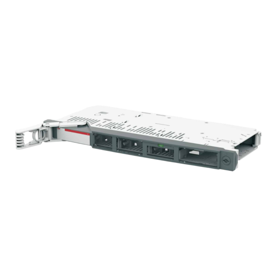
- Page 1 — I N S TA L L AT I O N I N S T R U C TI O N Switch Disconnector Fuse Slimline XRG00...
-
Page 2: Table Of Contents
— Table of contents Use of symbols Busbar overview Manual operation Motor operation Fuse replacement Accessory... -
Page 3: Use Of Symbols
SWITC H D ISCO NNEC TO R FUSE, XRG 00 — Use of symbols Hazardous voltage Caution Warns about a situation where a hazardous Provides important information or warns voltage may cause physical injury to a per - about a situation that may have a detrimen - son or damage to equipment. - Page 4 If damage is evident, or there is vis - ible indication of rough handling, immedi- Warning ately file a damage claim with the transpor - tation company, and notify your local ABB sales office. HAZARD OF EQUIPMENT Do not remove the shipping package until OVERTURNING ready to install the switch.
- Page 5 SWITC H D ISCO NNEC TO R FUSE, XRG 00 — Read these safety instructions carefully before using this product! HAZARD OF ELECTRIC SHOCK, EXPLOSION, OR ARC FLASH • Apply appropriate personal protective equipment and follow safe electrical work practices. Danger •...
-
Page 6: Busbar Overview
SWITC H D ISCO NNEC TO R FUSE, XRG 00 — Busbar overview 50/5-2p 50/5-3p 50/5-4p 50/10-2p 50/10-3p 50/10-4p... - Page 7 SWITC H D ISCO NNEC TO R FUSE, XRG 00 — Busbar overview 185/10-2p 77.5 185/10-3p 77.5 185/10-4p 97.5 77.5...
-
Page 8: Manual Operation
SWITC H D ISCO NNEC TO R FUSE, XRG 00 — Manual operation 45° Max. 4Nm Max. 4Nm M6 thread forming screw (not included) -
Page 9: Motor Operation
SWITC H D ISCO NNEC TO R FUSE, XRG 00 — Motor operation 45° 45° Max. 4Nm Max. 4Nm Pos. 3, 6 - M6 thread forming screw (not included) Pos. 5 - M5X8 thread forming screw with a TX30 head (included) - Page 10 SWITC H D ISCO NNEC TO R FUSE, XRG 00 — Motor operation Signal: >0.5 sec or permanent Close Open Manual operation: long hexagon bit size 3mm - approx. 40 revolutions Front cover must be locked before operating...
- Page 11 SWITC H D ISCO NNEC TO R FUSE, XRG 00 — Motor operation (*) Will go to NO at loss of +24V power supply, even when the XRG apparatus is in closed position. For indication purposes only. (*) Motor multiplug connect diagram is different from ITS+Motor configurations. Refer to the ITS page of instruction.
-
Page 12: Its
Connect, use the USB connector at the bottom side of the Ekip Display. The connection cable has to be the T&P cable kit (Order code : 1SDA066989R1 ) The Ekip Connect software tool can be downloaded for free at: http://library.abb.com... - Page 13 SWITC H D ISCO NNEC TO R FUSE, XRG 00 — Terminal Signal 24 VDC 24 V GND (0V) RS-485 0V RS-485 + (A) RS-485 - (B) Multiplug If a termination resistor is needed, it must be fitted to terminals 4 and 5 in the last ITS2.1 or ITS2.D unit in the multi drop line.
-
Page 14: Efm
SWITC H D ISCO NNEC TO R FUSE, XRG 00 — Red LED: One or more fuses are blown Green LED: All fuses are OK Diagram XR AC EFM Diagram XR DC 110/500 EFM F2 F3 11 NO 11 NO 13 NC 13 NC 12 NO/NC... - Page 15 SWITC H D ISCO NNEC TO R FUSE, XRG 00 — Application 280-880V 40-140 ± The EFM unit will survive an insulation test voltage of 1.6kV. However, by insulation test, we recommend that the EFM module can be completely removed by also disconnecting the internal plug to the rear side of the Multiplug.
-
Page 16: Fuse Replacement
SWITC H D ISCO NNEC TO R FUSE, XRG 00 — Fuse replacement Hex socket 8 mm... -
Page 17: Accessory
SWITC H D ISCO NNEC TO R FUSE, XRG 00 — Accessory Guide rail M6X16 thread forming screw with a TX30 head (included) - Page 18 SWITC H D ISCO NNEC TO R FUSE, XRG 00 — Accessory Multiplug...
- Page 19 SWITC H D ISCO NNEC TO R FUSE, XRG 00 — Accessory Contact extension M6: 9Nm M8: 15Nm 2.5Nm Pos. 2, 4 - TX20 head (fasteners included) Pos. 3 - bolt and nut hex socket 13 mm (fasteners included)
- Page 20 SWITC H D ISCO NNEC TO R FUSE, XRG 00 — Accessory...
- Page 21 SWITC H D ISCO NNEC TO R FUSE, XRG 00 — Accessory A-meter 1 2 3 4 Pin 1 mark T1-S2 T1-S1 X3-1 insulation tube X3-5 A-S2 T1-S1...
- Page 22 SWITC H D ISCO NNEC TO R FUSE, XRG 00 — Accessory Auxiliary switch snap out or in the multiplug to access or break connection...
- Page 23 SWITC H D ISCO NNEC TO R FUSE, XRG 00 — Accessory Auxiliary switch Diagram for multiplug with motor EFM NO EFM NO/NC EFM NC C.T.No.1( ) Position feedback NO C.T.No.2 Field closed Field open Field common C.T.No.3 +24VDC Neutral(0V) Diagram for multiplug without motor EFM NO EFM NO/NC...
- Page 24 SWITC H D ISCO NNEC TO R FUSE, XRG 00 — Accessory Switch replacement tool...
- Page 25 SWITC H D ISCO NNEC TO R FUSE, XRG 00 — Cable shrouds installation 1. Install the three cables (socket 13mm). 4. Insert the 3 pole cable shroud. 15 Nm 12mm 16...120 mm² 2. Open the 3 pole cable shroud 5.
- Page 26 SWITC H D ISCO NNEC TO R FUSE, XRG 00 — MNS arc protection back cover for XRG 1. Install the MNS arc protection back cover to the electrical cabinet . 2. Install 3 pole switch to the electrical cabinet. Note: For XRG00-50/5-3P 3P version...
- Page 27 SWITC H D ISCO NNEC TO R FUSE, XRG 00 — RBBS arc protection back cover for XRG 1. Install the RBBS arc protection back cover for XRG to the electrical cabinet. 2. Install 3 pole switch to the electrical cabinet. Note: For XRG00-50/10-3P For XRG00-50/10-3P with contact extensions...
- Page 28 SWITC H D ISCO NNEC TO R FUSE, XRG 00 — Notes...
- Page 29 SWITC H D ISCO NNEC TO R FUSE, XRG 00 —...
- Page 30 SWITC H D ISCO NNEC TO R FUSE, XRG 00 —...
- Page 31 SWITC H D ISCO NNEC TO R FUSE, XRG 00...
- Page 32 — Contact us ABB Oy Smart Power P.O. Box 622 FI-65101 Vaasa Finland https://new.abb.com/contact-centers > Low Voltage Products and Systems © Copyright 2019 ABB. All rights reserved. Specifications subject to change without notice.