NEC 78K0R - Save It! Manuals
Manuals and User Guides for NEC 78K0R - Save It!. We have 2 NEC 78K0R - Save It! manuals available for free PDF download: User Manual
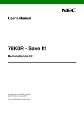
NEC 78K0R - Save It! User Manual (52 pages)
Demonstration Kit for the 78K0R 16-bit microcontroller family
Brand: NEC
|
Category: Motherboard
|
Size: 3.6 MB
Table of Contents
Advertisement
NEC 78K0R - Save It! User Manual (52 pages)
Brand: NEC
|
Category: Motherboard
|
Size: 3.24 MB
Table of Contents
Advertisement