Sign In
Upload
Manuals
Brands
Siemens Manuals
Controller
LME73
Siemens LME73 Manuals
Manuals and User Guides for Siemens LME73. We have
3
Siemens LME73 manuals available for free PDF download: Technical Instructions, Basic Documentation, Manual
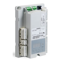
Siemens LME73 Basic Documentation (116 pages)
Burner control
Brand:
Siemens
| Category:
Safety Equipment
| Size: 2.94 MB
Table of Contents
Table of Contents
3
1 Safety Notes
8
Warning Notes
8
Mounting Notes
9
Installation Notes
10
Electrical Connection of Flame Detectors
11
Commissioning Notes
12
Standards and Certificates
13
Lifetime
14
Disposal Notes
14
Typographical Conventions
15
Safety Notes
15
Qualified Personnel
15
Correct Use
15
2 System Makeup / Function Description
16
Features
17
3 Type Summary
18
Burner Controls
18
Program Module
19
PME7 with Mains Voltage AC 120 V
19
PME7 with Mains Voltage AC 230 V
21
External Display and Operating Units
23
Flame Detectors
24
Actuators
25
Pressure Switch
25
Dummy Plugs for RJ11
25
Connector Sets for LME7
26
Service- Tools
27
4 Technical Data
28
Basic Unit LME7
28
Terminal Rating Inputs
29
Terminal Rating Outputs
30
Cable Lengths
32
Actuators
33
Cross-Sectional Areas
33
RAST5 Connector
34
RAST3.5 Connector
34
Signal Cable AGV50
34
Azl2 Bci
34
Dummy Plug for RJ11
34
Environmental Conditions
35
Flame Supervision
36
Ionization Probe
36
QRA2 / QRA4 / QRA10 (LME71 / LME73 Only)
38
Qrb1/Qrb3/ Qrb4
39
Qrc
41
5 Dimensions
42
6 Function
43
Preconditions for Burner Startup
43
Undervoltage
43
Controlled Intermittent Operation
43
Control Sequence in the Event of Fault
44
Resetting the LME7
44
Restart Limitation
45
Restart in the Event of Loss of Flame
45
Repetition in Case of no Flame Is Established by the End of Safety Time (TSA)
45
7 Operation, Indication, Diagnostics
46
Operation
46
Indication of Operating State
46
Diagnostics of Cause of Fault
47
8 Inputs / Outputs
49
9 Connection Diagram AGG9 Connector
50
Lme71
50
Lme72
51
Lme73
52
10 LME7 Burner Control
53
Description of Inputs and Outputs
53
Digital Input
54
Safety Loop Terminal X3-04 Pin 1 and 2
54
Input for External Controller (ON/OFF) Terminal X5-03 Pin 1
54
Air Pressure Switch Terminal X3-02
55
Input Gas Pressure Switch-Min
55
11 Multistage or Modulating Mode with Actuator
56
Relevant Parameters
56
Connection Diagram for Feedback Potentiometer ASZ12.33
56
Connection Diagram for Load Controller (LME71/LME73 Only)
57
Actuators
57
Function
57
Load Controller Inputs
58
3-Position Step Input Terminal X5-03
58
Analog Input Terminal X65 (LME71/LME73 Only)
58
Selection Source Preset Output Analog / 3-Position Step Input (Parameter 654) (LME71/LME73 Only)
58
Actuator Output Terminal X2-09
58
Setting the Maximum Running Time of the Actuator (Parameter 259 / 260 Timeout)
58
Multistage / Modulating Mode Via 3-Position Step Input Terminal X5-03
59
Maximum Possible Resolution
59
Modulating Mode Via Analog Input Signal Terminal X65 (LME71/LME73 Only)
59
Standardization of Modulation Range
59
Setting the Minimum Power Control Step (Dead Band) (Parameter 123)
60
(LME71/LME73 Only)
60
User Limitations / Application Examples
61
12 Safety Notes Relating to Operation of AZL2
62
13 Operation Via AZL2
63
Description of the Unit / Display and Buttons
63
Meaning of Symbols on the Display
64
Special Functions
64
Manual Lockout
64
Operation
65
Normal Display
65
Display in Standby Mode
65
Display During Startup / Shutdown
65
Display of Program Phases
65
List of Phase Display (Display Depending on Program)
66
Display of Operating Position
67
Fault Status Messages, Display of Errors and Info
68
Display of Errors (Faults) with Lockout
68
Reset
68
Menu-Driven Operation
69
Assignment of Levels
69
Info Level
70
Display of Info Level
70
Display of Info Values
71
Identification Date
71
Identification Number
71
Identification of Burner
72
Number of Startups Resettable
73
Total Number of Startups
74
End of Info Level
74
Service Level
75
Display of the Service Level
75
Display of Service Values
76
Error History
76
Mains Voltage
76
Intensity of Flame
76
End of Service Level
76
Parameter Level
77
Entering the Password
78
Changing the Heating Engineer's Password
80
Changing the Oem's Password
82
Backup
83
Restore
85
Operating Variants of the Parameters
87
Parameters Without Index, with Direct Display
87
Example of Parameter 225 (Prepurge Time) on the Parameter Level
87
Parameters Without Index, with no Direct Display
89
Example of Parameter 224 (Specified Time Air Pressure Switch) on the Parameter Level
89
Parameters with Index, with or Without Direct Display
91
Example of Parameter 701: Actual Error on the Service Level
91
14 Error Code List with Operation Via External AZL2 Display
94
15 Operation Via Internal LED
96
Description of Display and Buttons
96
Normal Display
97
Display in Standby Mode
97
Display During Startup / Shutdown
97
Display of Program Phases
97
List of Phase Display
98
Display of Operating Position
100
Special Functions
100
Manual Lockout
100
Fault Status Messages, Display of Errors
101
Display of Errors (Faults) with Lockout
101
Display of Flame Current ION or QRA
102
Reset
102
Display of Preset Output
103
Manual Adjustment (Depending on the PME7)
104
Position of Actuator or Speed of PWM Fan in Modulating Operation with Analog Signal
104
Initial Startup with a New PME7 or in Case of Replacement of the PME7
107
Manual Backup
109
Error During Backup Process
110
Manual Restore
111
Errors During the Restore Process
112
Reset
112
16 List of Figures
116
Advertisement
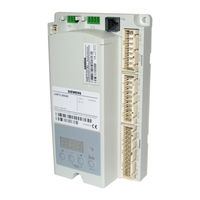
Siemens LME73 Manual (106 pages)
Burner
Brand:
Siemens
| Category:
Controller
| Size: 3.69 MB
Table of Contents
Table of Contents
3
1 Safety Notes
8
Warning Notes
8
Mounting Notes
9
Installation Notes
10
Electrical Connection of Flame Detectors
11
Commissioning Notes
12
Standards and Certificates
13
Lifetime
14
Disposal Notes
14
Typographical Conventions
15
Safety Notes
15
2 System Makeup / Function Description
16
Features
17
3 Type Summary
18
Burner Controls
18
Program Module
19
PME7 with Mains Voltage AC 120 V
19
PME7 with Mains Voltage AC 230 V
20
External Display and Operating Units
21
Flame Detectors
21
Actuators
22
Pressure Switch
22
Dummy Plugs for RJ11
22
Connector Sets for LME7
23
Service- Tools
24
4 Technical Data
25
Basic Unit LME7
25
Terminal Rating Inputs
26
Terminal Rating Outputs
27
Cable Lengths
28
Actuators
28
Cross-Sectional Areas
28
RAST5 Connector
29
RAST3.5 Connector
29
Signal Cable AGV50
29
Azl2 ↑ Bci
29
Dummy Plug for RJ11
29
Environmental Conditions
30
Flame Supervision
31
Ionization Probe
31
Flame Detector QRA2 / QRA4 / QRA10
33
5 Dimensions
34
6 Function
35
Preconditions for Burner Startup
35
Undervoltage
35
Controlled Intermittent Operation
35
Control Sequence in the Event of Fault
36
Resetting the Burner Control
36
Limitation of Repetitions
37
Repetition in Case of Loss of Flame
37
Repetition in Case of no Flame Is Established by the End of Safety Time (TSA)
37
7 Operation, Indication, Diagnostics
38
Operation
38
Indication of Operating State
38
Diagnostics of Cause of Fault
39
8 Inputs / Outputs
41
9 Connection Diagram AGG9 Connector
42
Lme71
42
Lme73
43
10 Basic Unit
44
Description of Inputs and Outputs
44
Digital Input
45
Safety Loop Terminal X3-04 Pin 1 and 2
45
Input for External Controller (ON/OFF) Terminal X5-03 Pin 1
45
Air Pressure Switch Terminal X3-02
46
Input Gas Pressure Switch-Min
46
11 Multistage or Modulating Mode with Actuator
47
Relevant Parameters
47
Connection Diagram for Feedback Potentiometer ASZ12.33
47
Connection Diagram for Load Controller
48
Actuators
48
Function
48
Load Controller Inputs
49
3-Position Step Input Terminal X5-03
49
Analog Input Terminal X65
49
Selection Source Preset Output Analog / 3-Position Step Input (Parameter 654)
49
Actuator Output Terminal X2-09
49
Setting the Maximum Running Time of the Actuator (Parameter 259 / 260 Timeout)
49
Multistage / Modulating Mode Via 3-Position Step Input Terminal X5-03
50
Maximum Possible Resolution
50
Modulating Mode Via Analog Input Signal Terminal X65
50
Standardization of Modulation Range
50
Setting the Minimum Power Control Step (Dead Band) (Parameter 123) in Modulating Mode Via Analog Input Signal Terminal X65
51
User Limitations / Application Examples
52
12 Safety Notes Relating to Operation of AZL2
53
13 Operation Via AZL2
54
Description of the Unit / Display and Buttons
54
Meaning of Symbols on the Display
55
Special Functions
55
Manual Lockout
55
Operation
56
Normal Display
56
Display in Standby Mode
56
Display During Startup / Shutdown
56
Display of Program Phases
56
List of Phase Display (Display Depending on Program)
57
Display of Operating Position
58
Fault Status Messages, Display of Errors and Info
59
Display of Errors (Faults) with Lockout
59
Reset
59
Menu-Driven Operation
60
Assignment of Levels
60
Info Level
61
Display of Info Level
61
Display of Info Values
62
Identification Date
62
Identification Number
62
Identification of Burner
63
Number of Startups Resettable
64
Total Number of Startups
65
End of Info Level
65
Service Level
66
Display of the Service Level
66
Display of Service Values
67
Error History
67
Mains Voltage
67
Intensity of Flame
67
End of Service Level
67
Parameter Level
68
Entering the Password
69
Changing the Heating Engineer's Password
71
Changing the Oem's Password
73
Backup
74
Restore
76
Operating Variants of the Parameters
78
Parameters Without Index, with Direct Display
78
Example of Parameter 225 (Prepurge Time) on the Parameter Level
78
Parameters Without Index, with no Direct Display
80
Example of Parameter 224 (Specified Time Air Pressure Switch) on the Parameter Level
80
Parameters with Index, with or Without Direct Display
82
Example of Parameter 701: Actual Error on the Service Level
82
14 Error Code List with Operation Via External AZL2 Display
85
15 Operation Via Internal LED
87
Description of Display and Buttons
87
Normal Display
88
Display in Standby Mode
88
Display During Startup / Shutdown
88
Display of Program Phases
88
List of Phase Display
89
Display of Operating Position
91
Special Functions
91
Manual Lockout
91
Fault Status Messages, Display of Errors
92
Display of Errors (Faults) with Lockout
92
Display of Flame Current ION or QRA
93
Reset
93
Display of Preset Output
94
Manual Adjustment (Depending on Program Module)
95
Position of Actuator or Speed of PWM Fan in Modulating Operation with Analog Signal
95
First Startup with a New Program Module or in Case of Replacement of Program Module
98
Manual Backup
100
Error During Backup Process
101
Manual Restore
102
Errors During the Restore Process
103
Reset
103
16 List of Figures
106
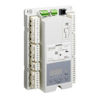
Siemens LME73 Technical Instructions (140 pages)
Burner Controls
Brand:
Siemens
| Category:
Controller
| Size: 6.3 MB
Table of Contents
Table of Contents
3
Introduction
9
Document No. LME
9
LME7 System Builder
10
Mounting
18
Important Safety Notes
20
Approvals
21
LME71 Wiring Diagrams
25
LME71 Parameter List
28
LME71 Phase Diagrams
35
LME73 Wiring Diagrams
41
LME73 Parameter List
44
LME73 Phase Diagrams
49
LME75 Wiring Diagrams
55
LME75 Parameter List
57
LME75 Phase Diagrams
62
Section 5: Commissioning
65
Commissioning a New LME7 Burner Control
67
Parameter Backups / Restores
68
Displaying the Flame Signal from the LME7 Burner Control
69
Displaying the Actuator Position / PWM Blower Speed from the LME7 Burner Control
70
Control
70
AZL23 Display Unit Icons
70
Introduction
73
Document No. LME
73
PWM Blower Fundamentals
73
Centrifugal Blower Fundamentals
74
Blower Speed Monitoring
75
Commissioning the LME7 When Using a PWM Blower
77
Adjusting P0, P1, and P2 Via the LME7 Built-In Display
79
Adjusting P0, P1, and P2 Via the AZL23 Display Unit
80
Additional Tips for Burners with PWM Blowers
81
Troubleshooting Introduction
85
Complete Fault Code List
87
Other Common Faults
91
Introduction
95
Physical Connections
95
Status LED
96
Tx/Rx LED
96
Modbus RTU Connection Details
97
Bacnet MS/TP Connection Details
98
Using the OCI417 Configuration Utility
99
Updating the OCI417.10 Firmware
101
Modbus Mapping
102
Bacnet Mapping
105
Unused Inputs
107
ACS410 Software Introduction
111
Software Installation
112
Connecting to a PC
113
Saving a Parameter Set to a PC
114
Uploading a Parameter Set to an LME7
115
Creating an LME7 Startup Report
116
Synchronizing the LME7 and PME Parameters
117
Saving and Viewing Trends
118
Viewing the Status Screen
120
Appendix A: Application Guide
124
Honeywell Modutrol IV Motor with the LME75
124
Two Flame Detectors
135
Advertisement
Advertisement
Related Products
Siemens LME7 Series
Siemens LME75
Siemens LME71
Siemens LME71.000A1
Siemens LME71.000A2
Siemens LME72.000A2
Siemens LME73.000A1
Siemens LME73.000A2
Siemens LME22.131A2
Siemens LME22.331A1
Siemens Categories
Industrial Equipment
Controller
Control Unit
Oven
Washer
More Siemens Manuals
Login
Sign In
OR
Sign in with Facebook
Sign in with Google
Upload manual
Upload from disk
Upload from URL