Beko METPOINT BDL compact Installation And Operating Manual
Hide thumbs
Also See for METPOINT BDL compact:

Related Manuals for Beko METPOINT BDL compact


Summary of Contents for Beko METPOINT BDL compact
- Page 1 EN - english Installation and operating manual Intelligent screen saver METPOINT BDL compact ®...
-
Page 2: Table Of Contents
9.3.2. Galv. isolated pulse option ............................. 19 9.4. Terminal assignment connector "E" (RS485 - Modbus) ....................... 20 9.5. Terminal assignment connector "A – B" (alarm relay) ......................20 9.6. Connection of BEKO sensors ..............................22 9.6.1. Connection of METPOINT SD11 / SD21 ........................22 ®... - Page 3 11.1.2. Home after switching-on ............................. 44 11.2. Settings ......................................44 11.2.1. Password ..................................45 11.2.2. Sensor settings ................................45 11.2.2.1. Selecting sensor type (example: BEKO Digital sensor) ..............46 11.2.2.2. Labelling measurements and defining resolution (decimals) ............48 11.2.2.3. Recording measuring data ........................49 11.2.2.4. Alarm settings ............................. 49 11.2.2.5.
- Page 4 Installation and operating manual 11.2.4. Backlight ..................................76 11.2.5. Cleaning ................................... 76 11.2.6. System Status ................................. 77 11.2.7. Virtual channels (optional) ............................77 11.2.7.1. Activating "virtual channels” option ...................... 77 11.2.7.2. Virtual channel settings ..........................78 11.2.7.3. Selecting sensor type ..........................78 11.2.7.4. ...
-
Page 5: Safety Instructions
Installation and operating manual 1. Safety instructions 1.1. Pictograms and symbols General hazard symbol (danger, warning, caution) General instructions Observe installation and operating instructions (on the type plate) Observe installation and operating instructions 1.2. Signal words according to ISO 3864 and ANSI Z.535 Imminent danger DANGER Consequences of non-compliance: serious or even fatal injury... -
Page 6: General Safety Instructions
If you have any queries regarding the content of this installation and operating manual, please contact BEKO TECHNOLOGIES. WARNING! Risk of injury to personnel with insufficient qualification! Incorrect operation of the device might cause serious injury or damage to property. All tasks described in this operating manual must be performed by skilled technical personnel who meet the criteria outlined below. -
Page 7: Device Features
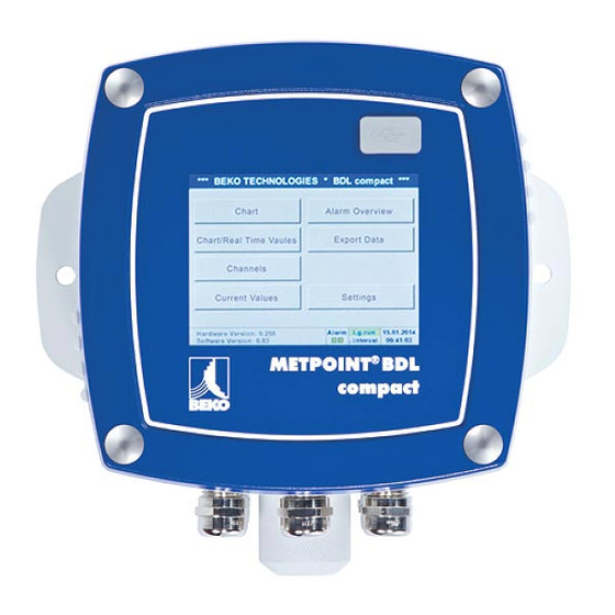
An alarm message can be sent e-mail through the BEKO web server and the Ethernet connection. All relevant information is displayed on the 3.5" colour display with an intuitive and barrier-free touch screen. The display shows measurements, curves and limit exceedances. -
Page 8: Proper Use
Installation and operating manual 3. Proper use The METPOINT BDL compact data logger has been specifically designed for the stationary measured data acquisition and ® storage of analog and digital input signals; the device must not be operated in potentially explosive atmospheres. The METPOINT BDL compact data logger is exclusively designed and constructed for the proper application purpose that ® is described herein and must only be used accordingly. A check in order to ascertain whether or not the device is suitable for the chosen employment must be carried out by the user. The technical data specified in data sheet are binding. -
Page 9: Storage And Transport
METPOINT BDL compact for visible damage. If you detect such damage, ® immediately notify the carrier company and BEKO TECHNOLOGIES or one of its agents. WARNING! Overheating Overheating can damage the evaluation electronics. Observe the permissible storage, transport and operating temperature (protect measuring device from direct sunlight). -
Page 10: Technical Data
4 (2x2) sensor inputs for analog and digital sensors, free assignment Sensor signals Analog signals: 0 - 1/10/30 V Pulse signals Pt100; Pt1000 Digital signals: RS485, BEKO-SDI Alarm outputs (alarm relays) 2x floating switchover contacts freely programmable, alarm management Analog output and pulse output Looped with sensors with own signal output, e.g. - Page 11 Operating temperature: -30 … +60 °C BEKO sensors Digital BEKO sensors for pressure dew point and consumption with RS485 interface, Series: DPM SD23, FLM SFxx Digital BEKO sensors for dew point and consumption with SDI interface, Series: DP 109, DP 110, FS 109, FS 211 Analogue BEKO sensors preconfigured for pressure, temperature, consumption, current clamp,...
-
Page 12: Dimensions And Mounting
The device can be integrated into a control panel or mounted on a wall, using suitable wall plugs and screws. For details, see drawing below. Dimensions for wall mounting 180 (7.1) 160 (6.3) 140 (5.5) 115 (4.5) *** BEKO TECHNOLOGIES * BDL compact *** Chart Alarm overview Chart/Real time values Export/Import Channels Real time values Settings 2 x O 6,5 (0.3) - Page 13 Installation and operating manual Dimensions for control panel installation 140 (5.5) 67 (2.6) 10 (0.4) 109 (4.3) *** BEKO TECHNOLOGIES * BDL compact *** Chart Alarm overview Chart/Real time values Export/Import Channels Real time values Settings Hardware Version: 1.21 Lg.run 24.06.2014...
-
Page 14: Installation
Installation and operating manual 8. Installation 8.1. Safety instructions DANGER! Mains voltage Risk of serious or even fatal injury from electric shock when coming into contact with non-insulated, powered components. Actions: • For the electrical installation of the device, adhere to all applicable regulations (e.g. VDE 0100). •... - Page 15 Installation and operating manual DANGER! Mains voltage When wiring the power supply line, ensure that the double or reinforced insulation between the electric circuits and the secondary circuit remains intact. NOTICE Insulation The additional insulation must be suitable for a test voltage of 1500 VAC. The thickness of the insulation must be at least 0.4 mm (e.g.
-
Page 16: Prevention Of Electrostatic Discharge (Esd)
Installation and operating manual 8.1.1. Prevention of electrostatic discharge (ESD) DANGER! Risk of damage from ESD The device contains electronic components that might be destroyed by electrostatic discharge (ESD). Avoid contact with persons or objects that are electrically charged. In the worst case, components sensitive to ESD might be instantly destroyed when touched or fail after start-up. -
Page 17: Notes For Installation
Installation and operating manual 8.2. Notes for installation 8.2.1. Protection class of housing (IP code) The METPOINT BDL compact data logger meets the requirements of protection class IP 44 according to EN 60529. ® The protection class of a housing is indicated by the two-digit IP code. The first digit indicates the protection rating with to persons and objects), the second digit indicates the rating for protection against water ingress. IP 44 according to EN 60529 International Protection Protection against access to hazardous parts with a wire (Ø... -
Page 18: Terminal Assignment And Wiring Diagram Of Metpoint ® Bdl Compact
Installation and operating manual 9. Terminal assignment and wiring diagram of METPOINT BDL compact ® Connections at rear of device 1 2 3 1 2 3 1 2 3 4 5 6 7 8 1 2 3 4 5 6 7 8 9 1 2 3 4 5 6 7 1 2 3 4 5 6 7 8 1 2 3 4 5 6 7... -
Page 19: Terminal Assignment Connector "A1 - B2" (Analog And Digital Channels)
Installation and operating manual 9.2. Terminal assignment connector "A1 – B2" (analog and digital channels) Both boards are equipped with internal bridges Analog Board Digital Board Depending on the selected option, the following combinations are supported: Channel Combination D = digital channel A = analog channel 9.3. -
Page 20: Terminal Assignment Connector "E" (Rs485 - Modbus)
Installation and operating manual 9.4. Terminal assignment connector "E" (RS485 - Modbus) 9.5. Terminal assignment connector "A – B" (alarm relay) The alarm outputs are designed as floating switchover contacts. The alarm signal can be forwarded to a control desk, etc. through the floating contacts. The connectors for the alarm contacts are labelled as "A" and "B". DANGER! Mains voltage When wiring the electric power supply line, ensure that the double or reinforced insulation between the electric circuits and the secondary circuit remains intact. - Page 21 Installation and operating manual Connections at rear of device 1 2 3 1 2 3 1 2 3 4 5 6 7 8 1 2 3 4 5 6 7 8 9 1 2 3 4 5 6 7 1 2 3 4 5 6 7 8 1 2 3 4 5 6 7 1 2 3 4 5 6 1 2 3 4 5 6 7...
-
Page 22: Connection Of Beko Sensors
Installation and operating manual 9.6. Connection of BEKO sensors The connection diagram shows the options for the connection of the BEKO sensors. Sensor RS485 Pulse 0 - 10 V 4 - 20 mA 2-wire 3-wire 4-wire 2-wire 3-wire 4-wire SD11 / SD21... -
Page 23: Connection Of Metpoint ® Sd23
Installation and operating manual 9.6.2. Connection of METPOINT SD23 ® Pin assignment of plug-type connector, M12 x 1, 8-pin, A-coded Pin assignment of connector Pin assignment of connector Pin assignment of connector Transmitter side Bush side view Screw side 9.6.2.1. Analogue - 4-wire, 4 … 20 mA Connection diagram METPOINT SD23 and METPOINT BDL compact... -
Page 24: Analogue - 4-Wire, 0
Installation and operating manual 9.6.2.2. Analogue - 4-wire, 0 … 10 V Connection diagram METPOINT SD23 and METPOINT BDL compact ® ® SD23 (-) V - PT - I (+) V - PT 0 ... 10 V 0 ... 10 V Wire Pin assignment Pin assignment - sensor... -
Page 25: Sp11 / Sp21 / Sp61
Installation and operating manual 9.6.3. Connection of METPOINT SP11 / SP21 / SP61 ® Pin assignment of plug-type connector, M12 x 1, 4-pin, A-coded Pin assignment of connector Pin assignment of connector Pin assignment of connector Transmitter side Bush side view Screw side 9.6.3.1. -
Page 26: Sp22 / Sp62
Installation and operating manual 9.6.4. Connection of METPOINT SP22 / SP62 ® Pin assignment of plug-type connector, M12 x 1, 4-pin, A-coded Pin assignment of connector Pin assignment of connector Pin assignment of connector Transmitter side Bush side view Screw side 9.6.4.1. -
Page 27: Connection Of Metpoint ® Sf13 / Sf53
Installation and operating manual 9.6.5. Connection of METPOINT SF13 / SF53 ® Pin assignment of plug-type connector A, M12 x 1, 5-pin, A-coded (according to EN 61076-2-101) Pin assignment of connector Pin assignment of connector Pin assignment of connector Transmitter side Bush side view Screw side Pin assignment of plug-type connector B, M12 x 1, 5-pin, A-coded (according to EN 61076-2-101) -
Page 28: Analogue - 3-Wire, 4
Installation and operating manual 9.6.5.2. Analogue - 3-wire, 4 … 20 mA Connection by means of plug-type connector A. Connection diagram METPOINT SF13 / SF53 and METPOINT BDL compact (analogue board) ® ® SF13 / SF53 (+) I (-) V - PT - I 4 ... -
Page 29: Fs109 / Fs211
Installation and operating manual 9.6.6. Connection of METPOINT FS109 / FS211 ® Pin assignment of plug-type connector, M12 x 1, 5-pin, A-coded Pin assignment of connector Pin assignment of connector Pin assignment of connector Transmitter side Bush side view Screw side 9.6.6.1. -
Page 30: Connection Of Ocv Compact
Installation and operating manual 9.6.7. Connection of OCV compact 9.6.7.1. Analogue - 2-wire, 4 … 20 mA Connection diagram METPOINT OCV compact and METPOINT BDL compact ® ® compact X22:3 (+) I X22:4 4... 20 mA 4 ... 20 mA Assignment Wire Pin assignment... -
Page 31: Connection Of Pc 400
Installation and operating manual 9.6.8. Connection of PC 400 9.6.8.1. Digital - bidirectional RS485 bus system Connection diagram PC 400 and METPOINT BDL compact ® PC 400 (+) A / RS485 (-) B / RS485 RS485 Wire Pin assignment Pin assignment - sensor Function colour BDL compact... -
Page 32: Connection Of Further Sensors
Installation and operating manual 9.7. Connection of further sensors Further analogue and digital sensors compact can be connected to the METPOINT BDL compact. ® The different connection options are shown sorted according how the measuring signals are transmitted. 9.7.1. Analogue, 0/4 … 20 mA 9.7.1.1. Analogue - 2-wire 0/4 … 20 mA Connection diagram analogue 2-wire, 0/4... 20 mA (+) I 4... -
Page 33: Analogue - 4-Wire 0/4
Installation and operating manual 9.7.1.3. Analogue - 4-wire 0/4 … 20 mA Connection diagram analogue 4-wire, 0/4... 20 mA (+) I (-) V - PT - I 4... 20 mA 0/4 ... 20 mA 0 ... 1/10/30 V Pin assignment Pin assignment - sensor Function BDL compact... -
Page 34: Analogue - 4-Wire, 0
Installation and operating manual 9.7.2.2. Analogue - 4-wire, 0 … 1/10/30 V Connection diagram analogue 4-wire, 0 … 1/10/30 V (-) V - PT - I (+) V - PT 0 ... 1/10/30 V 0 ... 10 V Pin assignment Pin assignment - sensor Function BDL compact... -
Page 35: Digital - 4-Wire Sdi-Interface
Installation and operating manual 9.7.3.2. Digital - 4-wire SDI-interface Connection diagram 4-wire SDI-interface 4... 20 mA 0/4 ... 20 mA Pin assignment Pin assignment - sensor Function BDL compact Plus (+) connection, voltage supply PIN-1 Minus (-) connection, voltage supply PIN-2 Current output PIN-2... -
Page 36: Analogue - Galvanically Isolated Pulse Sensors
Installation and operating manual 9.7.5. Analogue - galvanically isolated pulse sensors Connection diagram pulse sensor (-) V - PT - I I = 2.5V - 30 V (+) V - PT 0 = 0V - 0.7 V Pin assignment Pin assignment - sensor Function BDL compact Pulse... -
Page 37: Resistance Sensors
Installation and operating manual 9.7.6. Resistance sensors 9.7.6.1. 2-wire resistance sensors Connection diagram 2-wire resistance sensors PT GND (-) V - PT - I (+) V - PT PT Supply Pin assignment Pin assignment - sensor Function BDL compact connection Minus (-) PIN-6 PT GND... -
Page 38: 4-Wire Resistance Sensors
Installation and operating manual 9.7.6.3. 4-wire resistance sensors Connection diagram 4-wire resistance sensors PT GND (-) V - PT - I (+) V - PT PT Supply Pin assignment Pin assignment - sensor Function BDL compact connection Minus (-) PIN-6 PT GND connection Minus (-) -
Page 39: Connection Of External Displays (Plc / Ztl)
Installation and operating manual 9.8. Connection of external displays (PLC / ZTL) Power signals for an external PLC / ZTL or external display unit can be tapped at the METPOINT BDL compact. ® The different connection options are shown sorted according how the measuring signals are transmitted. 9.8.1. Analogue, 0/4 … 20 mA 9.8.1.1. -
Page 40: Analogue - 4-Wire 0/4
Installation and operating manual 9.8.1.3. Analogue - 4-wire 0/4 … 20 mA Connection diagram analogue 4-wire, 0/4... 20 mA SPS / (+) I (-) V - PT - I 4... 20 mA 4 ... 20 mA 0/4 ... 20 mA Pin assignment Pin assignment - sensor Function... -
Page 41: Digital - 4-Wire Sdi-Interface
Installation and operating manual 9.8.2.2. Digital - 4-wire SDI-interface Connection diagram analogue 4-wire SDI-interface SPS / 4... 20 mA 4 ... 20 mA 0/4 ... 20 mA Pin assignment Pin assignment - sensor Function BDL compact Plus (+) connection, voltage supply PIN-1 Minus (-) connection, voltage supply PIN-2... -
Page 42: Connecting The Metpoint ® Bdl Compact With A Pc
Installation and operating manual 10. Connecting the METPOINT BDL compact with a PC ® NOTICE Static IP address The IP addresses of the PC and the METPOINT BDL compact must be static (DHCP off) and part of ® the same network. If the IP address of the METPOINT BDL compact has been changed, you must restart the device! ®... -
Page 43: Operation Of Metpoint Bdl Compact
Installation and operating manual 11. Operation of METPOINT BDL compact ® The BDL is operated through a menu-driven, intuitive touch screen. To select a menu option, touch it lightly with your finger or a soft-pointed pen. Caution: Do not use normal pens or pointed implements as these could damage the foil! After the sensors have been connected, they must be configured. Entries or changes can be made in the white fields. The measured values are displayed as values or in the form of curves. Text in green letters refers mainly to figures in the respective chapter. Important menus and menu options are also shown with green letters. The menu navigation is generally shown in green letters! -
Page 44: Home After Switching-On
Installation and operating manual 11.1.2. Home after switching-on Important: Before entering the sensor settings, select the language and set the time. Notice: Chapter 11.2.3.1 Language (English menu navigation: Home Settings Device Settings Set Language) Chapter 11.2.3.2 Date and time ... -
Page 45: Password
Confirm new password displayed in red. If you have forgotten your password, enter the master password and then a new password. The master password can be requested from BEKO TECHNOLOGIES GmbH, with the serial number of the METPOINT BDL compact specified in ® the request. -
Page 46: Selecting Sensor Type (Example: Beko Digital Sensor)
The following combinations are supported, depending on the METPOINT BDL compact model: ® Combination Channel D = digital channel A = analog channel 11.2.2.1. Selecting sensor type (example: BEKO Digital sensor) Home Settings Sensor-settings If no sensor has been configured yet, No sensor displayed in the type field. Touch the sensor text field to call up a list of ... - Page 47 Installation and operating manual Settings Sensor-settings A1 Home right arrow (2. page) Diameter Important: Unless it has been automatically set, enter the Inside diameter of the flow pipe. If the new sensor replaces another one, enter the Counter value of the previous sensor (optional). Confirm with OK and go back with left arrow...
-
Page 48: Labelling Measurements And Defining Resolution (Decimals)
Installation and operating manual Settings Home Sensor settings Confirm the changes with OK. The sensor configuration is now completed. For other sensor configuration options, see chapters 11.2.2.5 to 11.2.2.9. See also chapter 11.2.2.7 Labelling and configuring text fields Note: After confirming with OK, the field labels change to black. The values and settings are applied. Caution: Reference temperature and reference pressure (factory settings 20°C, 1000 hPa): All volume flow (m³/h) and consumption (m³) values shown on the display refer to 20 °C and 1000 hPa (according to ISO 1217). Alternatively, enter 0°C and 1013 hPa (=standard cubic metre according to DIN 1343) as the reference values. Do not enter the operating pressure or the operating temperature as the reference values! 11.2.2.2. -
Page 49: Recording Measuring Data
Installation and operating manual 11.2.2.3. Recording measuring data Home Settings Sensor-settings A1 Record button Press the Record buttons to select the measurements to be recorded and stored on the activated data logger. Caution: Prior to recording the selected measuring data, configure the data logger and then start it (see chapter 11.2.3 Logger settings (data logger)). 11.2.2.4. Alarm settings ... - Page 50 Installation and operating manual Settings Home Sensor settings A1 Alarm button Relay buttons You can choose between 5 different delays. The set delays (T1 to T4) apply to all the relays. s = second m = minute h= hour Settings Sensor-settings A1 Home Alarm button...
-
Page 51: Advanced Settings (Scaling Of Analog Output)
Installation and operating manual Settings Home Sensor settings Screen of channel A1 after alarm configuration and activation. Press to save and apply the settings. 11.2.2.5. Advanced settings (scaling of analog output) Home Settings Sensor-settings A1 right arrow (2. page) Advanced settings In the Advanced settings, you can determine whether the 4-20 mA analog output of the sensor is to be based on flow volume or velocity. -
Page 52: Beko Digital Dew Point Sensor
Installation and operating manual 11.2.2.6. BEKO Digital dew point sensor Step 1: select a free sensor channel Home Settings Sensor settings Step 2: select type "BEKO Digital" Home Settings Sensor settings Type BEKO-Digital Step 3: confirm 2x with OK Configuration: see chapter 11.2.2.7 Labelling and configuring text fields) ... -
Page 53: Labelling And Configuring Text Fields
Installation and operating manual 11.2.2.7. Labelling and configuring text fields Home Settings Sensor settings If the data logger is activated, the following window appears. Press to activate the data logger. (Data loggers are only activated if the relevant settings and recordings have been configured.) Note: Before entering or changing sensor settings, set... - Page 54 Installation and operating manual Settings Sensor-settings A1 Home Type Touch the Type text field and select one of the available options Home Settings Sensor-settings A1 right arrow (2. page) Unit Preselection of matching Units. Home Settings Sensor settings A1 right arrow (2. page) ...
- Page 55 Installation and operating manual Home Settings Sensor settings A1 right arrow (2. page) Gas constant Preselection of matching Units. The remaining text fields can be labelled and configured in the same manner. For details, see chapter 11.2.2.7 Labelling and configuring text fields! Home Settings Sensor settings A1 right arrow (2. page) If a text field is displayed with red text, the ...
-
Page 56: Configuring Analog Sensors
BDL compact models with fully equipped analog board. ® Overview of the possible Type settings, including examples. BEKO-Digital see chapter 11.2.2.8.1 Selecting sensor type (example: BEKO Digital sensor) and chapter 11.2.2.1 BEKO Digital dew point sensor Alarm Record buttons, the Resolution... - Page 57 Installation and operating manual Settings Sensor-settings B1 Home Unit Preselection of suitable units for 0/4 – 20 Press the Page button to page forward. If required, define User units (user-defined units). Home Settings Sensor-settings Type 0/4 – 20 mA Here: Type 4 –...
-
Page 58: Type "Pulse
Installation and operating manual 11.2.2.8.2. Type PT100x and KTY81 Home Settings Sensor-settings B2 right arrow (2. page) Type In the example, sensor type PT100 Unit °C have been chosen. Alternatively, select the sensor types PT1000 and KTY81, and Unit °F. - Page 59 Installation and operating manual Home Settings Sensor settings B2 right arrow (2. page) Consumption Units for the current Consumption Type Pulse. Notice: Here: cubic metres! Home Settings Sensor-settings B2 right arrow (2. page) Counter unit Available units for Counter unit Type Pulse...
- Page 60 Installation and operating manual 11.2.2.9.1. Type "No sensor" Home Settings Sensor-settings Type No sensor This option is used to declare a channel that is not in use as not configured. When returning from No sensor to the respective sensor settings, the respective channel (here: channel A1) displayed as free.
-
Page 61: Type "Modbus
Installation and operating manual 11.2.2.10. Type "Modbus" 11.2.2.10.1. Selecting and activating sensor type Step 1: select a free sensor channel Home Settings Sensor settings Step 2: select Modbus type Home Settings Sensor-settings Type Modbus Step 3: confirm with OK Enter a name (see chapter 11.2.2.7 “Labelling and configuring text fields”). - Page 62 Installation and operating manual Settings Sensor-settings A1 right arrow (2. page) Register address Home The sensor stores the measured values in registers. These values can be addressed by the BDL and read out via Modbus. For this purpose, specify the register addresses in the BDL.
- Page 63 Installation and operating manual Examples: Holding register – UI1(8b) - numerical value: 18 Select register type Holding register, data type U1 (8b) and byte order HByte LByte 18 => Data Order 1. Byte 2. Byte Holding register – UI4(32) - numerical value: 29235175522 AE41 5652 Select register type Holding register,...
- Page 64 Installation and operating manual Settings Sensor-settings A1 right arrow (2. page) Scal. text field Home Enter a factor that is applied to adjust the respective output value. Home Settings Sensor-settings A1 right arrow (2. page) OK Press the button to store and apply the user- defined factor.
- Page 65 Installation and operating manual 11.2.2.10.3. Modbus settings for METPOINT SD23 ® When connecting a METPOINT SD23 via Modbus, the following settings are required: ® Step 1: select a free sensor channel Home Settings Sensor settingsSelect a free channel (here: channel A1) Step 2: select Modbus type Home ...
-
Page 66: Device Settings
Installation and operating manual The settings for the register/data format apply to all registers. Step 6: enter Modbus parameters To enter the Modbus parameters, press the white buttons (1) – (4). The following parameters can be retrieved from the respective registers: Register Designation Register address... -
Page 67: Language
Installation and operating manual 11.2.3.1. Language Home Settings Device settings Language Select the language for the METPOINT BDL compact interface. ® 11.2.3.2. Date and time Home Settings Device settings Date & time Touch the Time zone field and enter the correct UTC. To cater for daylight saving time, check the Daylight saving box. -
Page 68: Network Settings
Installation and operating manual 11.2.3.3. Network settings Home Settings Device settings Network settings Here, a connection to a computer can be configured, with or without DHCP. Notice: If the DHCP box is ticked, the BDL is automatically integrated into the existing network. In this case, there is no need to manually configure the network settings. Alternatively, enter the relevant network settings in the fields: ... -
Page 69: Modbus (Slave)
Installation and operating manual 11.2.3.4. Modbus (Slave) RS485 Modbus bus/interface allows customers to connect their own systems (BMS, PLC, SCADA) to the METPOINT BDL compact. ® Settings Home Device settings Modbus settings Enter the transmission parameters for Modbus ID, baud rate, stop bit and parity. -
Page 70: Relay Settings
Installation and operating manual 11.2.3.5. Relay settings Home Settings Device settings Relay settings If the Relay buttons are activated, you have the option to permit relay reset upon an alarm. The relevant settings must be made in the password- protected Device settings menu. -
Page 71: System
Installation and operating manual 11.2.3.7. System Settings Home Device settings System Overview of system settings Important: Before carrying out an update, save the device settings to a USB memory stick! Notice: The yellow field shows the update options that are available. 11.2.3.7.1. System update Home Settings Device settings... - Page 72 Installation and operating manual 11.2.3.7.2. Saving device settings Home Export/Import Export system settings Pressing the SdCard button sets the storage medium. Home Export/Import Export system settings Pressing new file will initiate saving. It is possible to enter a name with up to 8 characters. By pressing OK, the entries made are accepted and saved.
- Page 73 Installation and operating manual 11.2.3.7.3. Check for updates (USB) Home Settings Device settings System Update system Check USB stick for new Software updates If the USB memory stick is correctly connected to the BDL, the letters change to black and the various available update options (software, pictures, etc.) are shown with a green tick to the left.
- Page 74 Installation and operating manual 11.2.3.7.4. Loading device settings Home Export/Import Import Settings After selecting the storage medium (SdCard or USB), a desired previously saved device setting can be selected and loaded. Important: After the channel and system settings have been reset, press the button and then press the Restart button to...
-
Page 75: Calibrating Touch Screen
Installation and operating manual If required, the BDL can be re-booted by pressing the Restart button. 11.2.3.8. Calibrating touch screen Home Settings Device settings Calibration touchscreen If required, the touch screen calibration can be changed. Press the Calibrate button. A calibration cross appears, first in the top left corner, then in the ... -
Page 76: Backlight
Installation and operating manual 11.2.4. Backlight Home Settings Set Backlight In this menu, you can adjust the Backlight of the display (15 -100%). Example: Backlight set to 50% Check the Dim after box to reduce the Backlight a minimum after the set time interval has elapsed (here: 15 minutes). -
Page 77: System Status
Installation and operating manual 11.2.6. System Status Home Settings System Status System Status menu provides information on the applied voltages and currents of the individual Channels, as well as on the voltage supply of the power supply units. In addition, the most important network parameters such as Hostand are displayed. -
Page 78: Virtual Channel Settings
Installation and operating manual 11.2.7.2. Virtual channel settings Home Settings Sensor-settings Virtual channels After the virtual channels have been activated, the 4 available channels are shown in the sensor settings menu. Note: By default, the channels are not preconfigured. 11.2.7.3. Selecting sensor type Home Settings Sensor-settings Virtual channels ... -
Page 79: Configuring Virtual Values
Installation and operating manual Settings Sensor-settings V1 Home Virtual channels Name Enter a Name for the virtual channel. 11.2.7.4. Configuring virtual values For each virtual channel, up to 8 virtual values can be calculated. These values must be activated separately: 11.2.7.4.1. - Page 80 Installation and operating manual Home Settings Sensor-settings Virtual channels V1 right arrow (2. page) 1st operand A1 Press a hardware or virtual channel button (e.g. A1) to call up a list of the available measuring channels or measurements including the defined virtual ...
- Page 81 Installation and operating manual 11.2.7.4.3. Defining operations Home Settings Sensor-settings Virtual channels V1 right arrow (2. page) 1st operation Touch the operation. The available mathematical operations are displayed. Press the respective button to select and apply an operation.
- Page 82 Installation and operating manual To enter the new unit, press the Edit button. Enter the unit and accept with OK. <- To correct an entry, press the button. <- button deletes the last character button deletes the entire value Important: After all values and operators have been entered, the system is able to perform calculations with 3 values and 2 operands as follows: Example:...
-
Page 83: Resolution Of Decimal Places - Labelling And Recording Data Values
Installation and operating manual 11.2.7.5. Resolution of decimal places – labelling and recording data values Home Settings Sensor-settings Virtual channels V1 Tool button Press the Tool button to view the Resolution decimal places, the Short name and the Value name. -
Page 84: Example: Calculation Of "Specific Performance
Installation and operating manual 11.2.7.6. Example: calculation of "specific performance" This example is based on a compressor plant with 3 compressors. The consumption is measured with an FS109 consumption probe at inputs A1 - B1, and an electricity meter at input B2. The total consumptions for air and energy, and the "specific performance" of the entire plant are calculated. - Page 85 Installation and operating manual Settings V1 right arrow (2. page) V1a Home Sensor settings Virtual channels For instructions regarding the input of the operands and operations, see chapters „11.2.7.4.2. Defining operands“ page 79 and „11.2.7.4.3. Defining operations“ page 81. The result for is the sum of consumption sensors (see result panel).
-
Page 86: Analog Total (Optional)
Installation and operating manual 11.2.8. Analog total (optional) The "Analog total" option allows you to calculate the consumption based on sensors with analog outputs, e.g. 0-1/10/30 V or 0/4 – 20 mA. 11.2.8.1. Activating "Analog total" option After having acquired the "Analog total" option, you must activate it. Home ... -
Page 87: Selecting Sensor Type
Installation and operating manual 11.2.8.2. Selecting sensor type See also chapter 11.2.2.8 Configuring analog sensors Home Settings Sensor settings If no sensor has been configured yet, No sensor displayed in the type field. Touch the type field (reading No sensor) to call up a list of available sensor types (see next step). Home Settings Sensor-settings B1 Type Select the required sensor type by pressing the respective button (here: 4-20 mA). -
Page 88: Web Server (Optional)
Installation and operating manual 11.3. Web server (optional) After having acquired the "web server" option, you must activate it. 11.3.1. Activating web server option Home Settings About BDL compact Press the button for "Analog total". You are prompted to enter the activation code. Enter your activation code and press the button. -
Page 89: User Interface
Installation and operating manual 11.3.2. User interface The user interface can be called up with any conventional web browser. To call up the user interface, enter the IP address of the web server in the address bar of the web browser (e.g. http:\\172.16.4.56). The start page is the information page. -
Page 90: Selecting Language
Installation and operating manual 11.3.2.2. Selecting language The web server user interface language is factory-set to German. If required, choose a different language from the dropdown list Available languages: • German • English NOTICE Restriction of access Access to certain menu options is restricted. To have read and write access to all settings, you must log in as Administrator and enter the password specified in „11.3.3. Login“ page 90 (e.g. 1234). For the configuration of additional users, call up the User menu, see chapter 11.3.10 page 96. -
Page 91: Favourites
Installation and operating manual 11.3.4. Favourites This menu provides access to 4 user-defined web pages (favourites) that can be configured for the display of measurements. This menu is accessible without prior login. Description Select user-defined page (favourite) Select channels and measurements to be displayed Select update interval for display Select font size for measurements 11.3.5. Status The status menu shows the statuses of the individual relays and the data logger. METPOINT BDL compact ®... -
Page 92: Current Value
Installation and operating manual 11.3.6. Current value This menu shows the current measurements transmitted by the connected sensors. You have the option to narrows the overview down to selected sensors and measurements. Description Select sensors to be displayed Select measurements to be displayed Select update interval for display Select font size METPOINT... -
Page 93: Display
Installation and operating manual 11.3.7. Display The menu shows the current METPOINT BDL GUI and enables you to configure the BDL. The display is automatically ® updated every 60 seconds. It is thus not a real-time display. Description Current METPOINT BDL touch screen display ® Buttons for the operation and configuration of the METPOINT ® Current alarm status of relays Current status of data logger Press the buttons to change the settings as if you were operating the BDL on site. -
Page 94: Chart
Installation and operating manual 11.3.8. Chart This menu is used to view charts. All measurements stored on the SD card can be displayed in the form of charts. Description Selection of measurements stored on the SD card Press the >>previous<< and >>next<< to move to the previous/next data record Period for the display of the measurements Select channel to be displayed Draw chart for selected channel Chart plotting area... -
Page 95: Alarmmail
Installation and operating manual 11.3.9. AlarmMail This menu allows you to have e-mail alerts sent to certain e-mail addresses, if a limit value is exceeded. The content of the message is preset, but you can add a brief comment. BDL ALARM Event: 12.06.2012 18:14:57 IP: 172.16.4.142 Hostname: BDL-PMA... -
Page 96: User
Installation and operating manual 11.3.10. User In this menu, you can configure the users of the web server and define their access rights. The access rights are assigned to user groups. The available user groups are listed in the table below: Access rights User/mail recip- User groups Info Status display Chart AlarmMail ient management no login Guest User Operator... -
Page 97: Data Logger Settings
Installation and operating manual 11.4. Data logger settings Home Settings Logger settings In the top row, select one of the pre-defined Intervals (1, 2, 5, 10, 15, 30, 60, and 120 seconds) for recording. Alternatively, enter a user-defined Interval in the white text field in the top right corner showing the currently selected Interval (here: 20 seconds). Notice: The longest possible Interval is 300 seconds (5 minutes). - Page 98 Installation and operating manual Home Settings Logger settings Enforce new logger file button Home Settings Logger settings Enforce new logger file button Comment Check the Enforce new logger file box to create a new recording file with the name/comment entered in the Comment text field.
- Page 99 Installation and operating manual Home Settings Logger settings Stop time button Check the Stop time box and enter the stop date/ time for the data logger recording in the fields below the box. Notice: When the Stop time box is checked, the current time plus 1 hour is displayed in the date/time field. Home ...
- Page 100 Installation and operating manual Home Settings Logger settings Start time button After the Start time and/or Stop time has been set, press the Start button to set the data logger to active. The data logger will start recording at the set time! Home ...
-
Page 101: Charts
Installation and operating manual 11.5. Charts Home Charts Caution: Only recordings that are completed can be viewed in the form of charts! Currently running recordings can be viewed with Chart/current values (see chapter 11.5.1 Chart/real time values). While a measurement is running, no values are displayed! Zooming and scrolling in Charts: The maximum time period that can be viewed in a chart is 1 day (24h). - Page 102 Installation and operating manual Home Chart Date Press the Date field to call up a calendar where you can select the desired date. Select saved measurements by Time (Start Stop time), by Comment and/or by File name (contains date in UK format). Home Chart Tool Button In the...
- Page 103 Installation and operating manual Home Chart Setup Unit Select the Unit of the recording to be displayed. Home Charts Tool Button Select the y-axis scaling with min., max. and grid. Press the A.Scale button to define calculation-based automatic scaling. To configure the other y-axes, proceed as described above! Four different grid settings with different Units Colours.
-
Page 104: Chart/Real Time Values
Installation and operating manual 11.5.1. Chart/Real time values Chart/Real time values Home One or more channels for the recording and the visualisation of the measurements can be selected here (e.g. on dew point sensor or a number of different sensors). Chart/Real time values Home ... - Page 105 Installation and operating manual For each channel a value can be selected for display in the Chart. Here: channel A1 has been selected. For each channel, select a value for visualisation in the Chart , and one value to be displayed In addition, you can define a Colour and the y-axis scaling factors (min,...
- Page 106 Installation and operating manual Home Channels Current values menu shows the current measurements of all the connected sensors. If a set alarm limit has been exceeded, the respective measured value flashes in yellow (Alarm 1) or red (Alarm Home Channels You have the option to select a channel to call up and check the settings.
-
Page 107: Current Values
Installation and operating manual 11.6. Current values Home Current values Current values view allows for the display of up to 5 user-defined measurements. If a set alarm limit has been exceeded, the respective measured value flashes in yellow (Alarm 1) or red (Alarm Notice: Changes to the layout must always be made in Setup menu! Home... -
Page 108: Alarm Overview
Installation and operating manual 11.7. Alarm overview Home Alarm overview In the alarm overview, you can immediately see whether the alarm is an Alarm 1 or an Alarm The type of the alarm is also shown in other menu: Home ... - Page 109 Installation and operating manual Home Export data Export logger data Press the Select buttons to select the Start time of the period you wish to export. The stored bitmaps captured within the set period are exported. Home Export data Export logger data change The selected date is highlighted in green.
-
Page 110: Screenshot Function
Installation and operating manual 11.9. Screenshot function This function allows you to store screenshots of charts, charts/current values, channels and current values on an USB memory stick or a SD card. 11.9.1. Saving screenshots Home Charts Home Chart/current values Home ... - Page 111 Installation and operating manual Home Export/Import Export screenshots Press the Select buttons to select the Start and End time of the period you wish to export. The stored bitmaps captured within the set period are exported. Home Export/Import Export screenshots Change The selected date is highlighted in green.
-
Page 112: Sd Card And Batteries
An integrated battery (button cell) ensures that the configuration data is not lost when the device is shut down. DANGER Battery and SD card The battery and the SD card must be changed by authorised skilled technical personnel of BEKO. Before changing the battery or SD card, ensure that the device is de-energised. Danger! Risk of damage from ESD The device contains electronic components that might be damaged or even destroyed by electrostatic discharge (ESD). -
Page 113: Cleaning/Decontamination
Installation and operating manual 13. Cleaning/decontamination NOTICE Observe display during cleaning The METPOINT BDL compact has a cleaning function which protects the display against ® unintentional operation when cleaning it. For details, see chapter „11.2.5. Cleaning“ page 76. To clean the METPOINT BDL compact plug-on display, use a damp (but not wet) cotton cloth or disposable tissue and a ®... -
Page 114: Dismantling And Disposal
BDL compact from BEKO TECHNOLOGIES GmbH can be returned to the manufacturer for disposal. ® If the BDL compact is not returned to BEKO TECHNOLOGIES GmbH for disposal, dispose of it according to waste code: Discarded electrical and electronic equipment other than those mentioned in 20 01 21, 20 01 23 20 01 36 and 20 01 35. - Page 115 Installation and operating manual METPOINT BDL compact ®...
-
Page 116: Declaration Of Conformity
Installation and operating manual 15. Declaration of Conformity METPOINT BDL compact ®... - Page 117 Installation and operating manual BEKO TECHNOLOGIES GMBH Im Taubental 7 41468 Neuss, GERMANY Phone: +49 2131 988-0 www.beko-technologies.com EU Declaration of Conformity We hereby declare that the products indicated hereafter comply with the stipulations of the relevant directives and technical standards. This declaration only refers to products in the condition in which they have been placed into circulation.
- Page 118 Tel. +86 21 508 158 85 info.cn@beko-technologies.cn BEKO Tecnológica España S.L. BEKO TECHNOLOGIES LIMITED BEKO TECHNOLOGIES INDIA Pvt. Ltd. Torruella i Urpina 37-42, nave 6 Unit 1010 Miramar Tower Plot No.43/1 CIEEP Gandhi Nagar E - 08758 Cervelló 132 Nathan Rd.