Huawei Telepresence TP3106 Installation Manual
Hide thumbs
Also See for Telepresence TP3106:
- User manual (75 pages) ,
- Quick start manual (6 pages) ,
- Commissioning manual (202 pages)

Related Manuals for Huawei Telepresence TP3106


Summary of Contents for Huawei Telepresence TP3106
- Page 1 7420001 HUAWEI TP3106&TP3118S&TP3118 Telepresence Installation Guide Issue Date 2013-11-08 HUAWEI TECHNOLOGIES CO., LTD.
- Page 2 All other trademarks and trade names mentioned in this document are the property of their respective holders. Notice The purchased products, services and features are stipulated by the contract made between Huawei and the customer. All or part of the products, services and features described in this document may not be within the purchase scope or the usage scope.
-
Page 3: Table Of Contents
8.6 Installing the Cable Troughs............................62 8.7 Installing the Microphones............................63 8.8 Installing the Multi-Functional Sockets........................65 8.9 Installing the Tabletop Display Buttons........................66 8.10 Checking the Multi-Functional Conference Table After Installation.................68 Issue 07 (2013-11-08) Huawei Proprietary and Confidential Copyright © Huawei Technologies Co., Ltd. - Page 4 14.1 Parts List...................................120 14.2 Installation Procedure...............................120 15 Installing the Multi-Functional Conference Table Decorative Parts......126 15.1 Parts List...................................127 15.2 Installation Procedure...............................127 16 Installing the Top Cooling Plates..................135 16.1 Parts List...................................136 Issue 07 (2013-11-08) Huawei Proprietary and Confidential Copyright © Huawei Technologies Co., Ltd.
- Page 5 HUAWEI TP3106&TP3118S&TP3118 Telepresence Installation Guide Contents 16.2 Installation Procedure...............................136 17 Parts List Sorted by Packing Case..................139 18 Screws and Accessories......................147 Issue 07 (2013-11-08) Huawei Proprietary and Confidential Copyright © Huawei Technologies Co., Ltd.
-
Page 6: About This Document
1 About This Document About This Document This guide is intended for qualified personnel who are responsible for installing the HUAWEI TP3106, TP3118S, or TP3118 telepresence system. The HUAWEI TP3106, TP3118S, and TP3118 have basically the same quantity of and installation method for most of their components (except their multi-functional conference tables). - Page 7 SwitchManager and the SwitchCentre. Symbol Conventions The symbols that may be found in this document are defined as follows. Issue 07 (2013-11-08) Huawei Proprietary and Confidential Copyright © Huawei Technologies Co., Ltd.
- Page 8 Screws of this type are mainly used to connect and secure surfaces with thinner cross-sections. Fixture The fixture is a tool used to determine the locations of parts in relation to each other during assembly. Issue 07 (2013-11-08) Huawei Proprietary and Confidential Copyright © Huawei Technologies Co., Ltd.
-
Page 9: Installation Precautions
Use the correct, special-purpose tools to perform high voltage AC operations. Do not use general purpose tools, or your own tools. Issue 07 (2013-11-08) Huawei Proprietary and Confidential Copyright © Huawei Technologies Co., Ltd. - Page 10 Signal Cable Bundling Signal cables must be bundled separately from heavy-current or high-voltage cables. The minimum distance between bundles is 150 mm. Issue 07 (2013-11-08) Huawei Proprietary and Confidential Copyright © Huawei Technologies Co., Ltd.
-
Page 11: Telepresence Room Decoration Requirements
To reproduce the experience of a real-life, in- person meeting, high-fidelity audio and HD video must also be delivered. This installation guide details the design principles and specifications for Huawei telepresence rooms, including principles for decoration, acoustics, illumination, and heating, ventilation, and air conditioning (HVAC) requirements. -
Page 12: Room Layout
To create a conformable meeting environment, telepresence rooms must be designed and laid out to relevant requirements. For details about the decoration instructions for telepresence rooms, see the Proposal for Decoration of the HUAWEI TP3106 Telepresence Room. System Dimensions Dimensions of the TP3106 (H x W x D): 1840 mm x 5600 mm x 3200 mm. See Figure 3-1. -
Page 13: Environmental Requirements
In a telepresence room, the background noise level must be ≤ 38 dB (with the door closed and all equipment turned off) before the telepresence system is installed. Issue 07 (2013-11-08) Huawei Proprietary and Confidential Copyright © Huawei Technologies Co., Ltd. -
Page 14: Power Supply And Network
Three independent power supply systems are required in a telepresence room to provide power to the illumination system, the telepresence system, and the air conditioning system respectively. Issue 07 (2013-11-08) Huawei Proprietary and Confidential Copyright © Huawei Technologies Co., Ltd. -
Page 15: Fire Control Facilities
Figure 3-3 shows the layout of the suspended ceiling fire control system in a telepresence room. Issue 07 (2013-11-08) Huawei Proprietary and Confidential Copyright © Huawei Technologies Co., Ltd. - Page 16 HUAWEI TP3106&TP3118S&TP3118 Telepresence Installation Guide 3 Telepresence Room Decoration Requirements Figure 3-3 Layout of the suspended ceiling fire control system Issue 07 (2013-11-08) Huawei Proprietary and Confidential Copyright © Huawei Technologies Co., Ltd.
-
Page 17: Installation Preparation
This chapter describes the preparation required before installing the telepresence system, including preparing tools, performing unpacking check, and setting IP addresses. 4.1 Tools List 4.2 Unpacking 4.3 Setting Parameters Issue 07 (2013-11-08) Huawei Proprietary and Confidential Copyright © Huawei Technologies Co., Ltd. -
Page 18: Tools List
Used for dismantling packages and mallet leveling tabletop segments. Diagonal Cuts cables and straps. pliers Safety Protect hands from injury. gloves Safety Protect eyes from dust. glasses Issue 07 (2013-11-08) Huawei Proprietary and Confidential Copyright © Huawei Technologies Co., Ltd. - Page 19 Open-end Caliber: 8 mm to 10 mm and 24 mm wrench to 28 mm. Rechargea Recommended model: Bosch GSR 18 V-LI. battery- powered electric screwdriv Issue 07 (2013-11-08) Huawei Proprietary and Confidential Copyright © Huawei Technologies Co., Ltd.
-
Page 20: Unpacking
When transporting, moving and installing equipment, parts, or components, never touch uncoated surfaces with sweat-soaked or dirty gloves. Table 4-3 lists the items to be checked. Issue 07 (2013-11-08) Huawei Proprietary and Confidential Copyright © Huawei Technologies Co., Ltd. - Page 21 4-3, unpack the cartons for acceptance. If the outer package is damaged or soaked, or the equipment has got wet and there is evidence of corrosion, stop unpacking and find the cause. Report the issue to the local Huawei representative office.
- Page 22 The following description and procedure uses the carton for packing boards as an example. Figure 4-2 illustrates the procedure for unpacking the carton. Issue 07 (2013-11-08) Huawei Proprietary and Confidential Copyright © Huawei Technologies Co., Ltd.
- Page 23 Check whether the number of boards is consistent with that specified on the carton label. Then, remove the boards from the carton. Check the number and type of boards against the Packing List, and accept them. Issue 07 (2013-11-08) Huawei Proprietary and Confidential Copyright © Huawei Technologies Co., Ltd.
- Page 24 If damage is identified, fill in the Cargo Replacement Application Form. Meanwhile, the supervisor must fill in the Cargo Shortage and Miscarriage Report and submit it to the local Huawei representative office within three days. If the delivered equipment is inconsistent with the stipulated items, move the unpacked equipment indoors for proper storage.
-
Page 25: Setting Parameters
Table 4-4. NOTICE l If items included differ from those listed in the table, contact the local Huawei representative office. l If any connector is damaged or loosened, or any cable is scratched, repair or replace the cable. Table 4-4 Item checklist for the equipment... - Page 26 Touch panel 172.16.21.65 Left tabletop 172.16.21.30 Default IP address: display 172.16.21.30. Center tabletop 172.16.21.31 Default IP address: display 172.16.21.30. Right tabletop 172.16.21.32 Default IP address: display 172.16.21.30. Issue 07 (2013-11-08) Huawei Proprietary and Confidential Copyright © Huawei Technologies Co., Ltd.
-
Page 27: Installation Overview
HD displays, tri-lens camera, and tabletop displays. To correctly and safely install a telepresence system, read this guide carefully before installation, and strictly follow the instructions herein during installation. Figure 5-1 describes the installation procedure. Issue 07 (2013-11-08) Huawei Proprietary and Confidential Copyright © Huawei Technologies Co., Ltd. - Page 28 HUAWEI TP3106&TP3118S&TP3118 Telepresence Installation Guide 5 Installation Overview Figure 5-1 Installation procedure Issue 07 (2013-11-08) Huawei Proprietary and Confidential Copyright © Huawei Technologies Co., Ltd.
-
Page 29: Installing The Racks
To ensure the successful installation and cable routing of other devices and high quality of telepresence conferences, the racks must be installed according to the instructions in this chapter. 6.1 Parts List 6.2 Installation Procedure Issue 07 (2013-11-08) Huawei Proprietary and Confidential Copyright © Huawei Technologies Co., Ltd. -
Page 30: Parts List
6-1, ensuring that the center rack is 570 mm from the rear wall. Figure 6-1 Location of the center rack 570mm Step 2 Install the connecting plates, as shown in Figure 6-2. Issue 07 (2013-11-08) Huawei Proprietary and Confidential Copyright © Huawei Technologies Co., Ltd. - Page 31 Step 3 Attach the left and right curved connecting rods. The methods for installing the left and right curved connecting rods are the same. The following procedure uses the right connecting rod as an example. See Figure 6-3. Issue 07 (2013-11-08) Huawei Proprietary and Confidential Copyright © Huawei Technologies Co., Ltd.
- Page 32 Step 4 Adjust all support legs to ensure that the distance between the top of the base of the rack (see Figure 6-4) and the floor is 120 mm. Issue 07 (2013-11-08) Huawei Proprietary and Confidential Copyright © Huawei Technologies Co., Ltd.
- Page 33 Step 5 Adjust the screws on the left and right sides of the HD display base until it is level with the side level line (red line shown in Figure 6-5), ensure that the distance between the side surface level and the floor is 630 mm. Issue 07 (2013-11-08) Huawei Proprietary and Confidential Copyright © Huawei Technologies Co., Ltd.
- Page 34 The distance between the left rack and the rear wall is the same as the distance between the right rack and the rear wall. The side surface level of each rack is 630 mm above the floor. Figure 6-6 shows the racks after installation. Issue 07 (2013-11-08) Huawei Proprietary and Confidential Copyright © Huawei Technologies Co., Ltd.
- Page 35 HUAWEI TP3106&TP3118S&TP3118 Telepresence Installation Guide 6 Installing the Racks Figure 6-6 Racks after installation Issue 07 (2013-11-08) Huawei Proprietary and Confidential Copyright © Huawei Technologies Co., Ltd.
-
Page 36: Installing The Hd Displays
Installing the HD Displays About This Chapter Each telepresence system utilizes three 65-inch HD displays (liquid crystal displays) to display video and presentations. 7.1 Parts List 7.2 Installation Procedure Issue 07 (2013-11-08) Huawei Proprietary and Confidential Copyright © Huawei Technologies Co., Ltd. -
Page 37: Parts List
To prevent injury, do not place hands at the rear of the HD displays. DANGER The HD displays are large and heavy. Be careful when lifting or moving them. Issue 07 (2013-11-08) Huawei Proprietary and Confidential Copyright © Huawei Technologies Co., Ltd. - Page 38 2, tightened using an H3 Allen wrench. Step 2 Mount the center HD display onto the center rack, as shown in Figure 7-2. Issue 07 (2013-11-08) Huawei Proprietary and Confidential Copyright © Huawei Technologies Co., Ltd.
- Page 39 Fine-tune the HD display base, if required, to ensure that the distance is 630 mm, as shown Figure 6-5. l Use a spirit level to check the center HD display along axes X and Y, as shown in Figure 7-3. Issue 07 (2013-11-08) Huawei Proprietary and Confidential Copyright © Huawei Technologies Co., Ltd.
- Page 40 After mounting the HD displays, ensure that: No gaps exist between the HD displays. All the HD displays are on the same plane. Figure 7-4 illustrates the HD displays after installation. Issue 07 (2013-11-08) Huawei Proprietary and Confidential Copyright © Huawei Technologies Co., Ltd.
- Page 41 Seven M6 x 16 countersunk screws are required for each of the center top brackets. Attach the six top brackets to the racks, as shown in Figure 7-5. Issue 07 (2013-11-08) Huawei Proprietary and Confidential Copyright © Huawei Technologies Co., Ltd.
- Page 42 Attach straight connecting rods to the center of the outer side of the left and right racks. The attachment method is the same for the left and right racks. The following procedure uses the right rack as an example. See Figure 7-6. Issue 07 (2013-11-08) Huawei Proprietary and Confidential Copyright © Huawei Technologies Co., Ltd.
- Page 43 Attach side connecting rods to the top and bottom of the left and right racks. The attachment method is the same for the left and right racks. The following procedure uses the right rack as an example. See Figure 7-7. Issue 07 (2013-11-08) Huawei Proprietary and Confidential Copyright © Huawei Technologies Co., Ltd.
- Page 44 Attach ladder stands to the outer side of the left and right racks. The attachment method is the same for the left and right racks. The following procedure uses the right rack as an example. See Figure 7-8. Issue 07 (2013-11-08) Huawei Proprietary and Confidential Copyright © Huawei Technologies Co., Ltd.
- Page 45 Mount side mounting frames to the left and right ladder stands. The mounting methods for the left and right racks are the same. The following procedure uses the left rack as an example. See Figure 7-9. Issue 07 (2013-11-08) Huawei Proprietary and Confidential Copyright © Huawei Technologies Co., Ltd.
- Page 46 Mount the mounting frame with smaller openings to the rear side of the ladder stand. Orient the screw bayonet toward the rack and fix it to the innermost spacer. Tighten all screws to complete. Issue 07 (2013-11-08) Huawei Proprietary and Confidential Copyright © Huawei Technologies Co., Ltd.
-
Page 47: Installing The Front Row Of The Multi-Functional Conference Table
Step 8 Install the tabletop display buttons. ----End 8.1 Parts List 8.2 Installing the Fixture 8.3 Installing the Multi-Functional Conference Table Stand 8.4 Installing the Tabletop Displays Issue 07 (2013-11-08) Huawei Proprietary and Confidential Copyright © Huawei Technologies Co., Ltd. - Page 48 8.6 Installing the Cable Troughs 8.7 Installing the Microphones 8.8 Installing the Multi-Functional Sockets 8.9 Installing the Tabletop Display Buttons 8.10 Checking the Multi-Functional Conference Table After Installation Issue 07 (2013-11-08) Huawei Proprietary and Confidential Copyright © Huawei Technologies Co., Ltd.
-
Page 49: Parts List
Left steel frame Center steel frame Right steel frame Tabletop display Tabletop display left backboard Tabletop display center backboard Tabletop display right backboard U-shaped board Side board Issue 07 (2013-11-08) Huawei Proprietary and Confidential Copyright © Huawei Technologies Co., Ltd. -
Page 50: Installing The Fixture
M6 x 25 screw Several Connecting rod 8.2 Installing the Fixture Context Before installing the multi-functional conference table, install the fixture to locate the table legs. Issue 07 (2013-11-08) Huawei Proprietary and Confidential Copyright © Huawei Technologies Co., Ltd. -
Page 51: Installing The Multi-Functional Conference Table Stand
Step 1 Place the four table legs to the corresponding seats of the fixture, with the edges of the table legs parallel to the those of the fixture, as shown in Figure 8-2. Figure 8-3 shows the table legs. Issue 07 (2013-11-08) Huawei Proprietary and Confidential Copyright © Huawei Technologies Co., Ltd. - Page 52 90-degree corners toward the HD displays. Step 2 Install the center (fan-shaped) steel plates, as shown in Figure 8-4. Issue 07 (2013-11-08) Huawei Proprietary and Confidential Copyright © Huawei Technologies Co., Ltd.
- Page 53 Align the screw holes. Secure the steel frame with five M6 x 16 countersunk screws. Step 4 Attach the connecting rod to the left center and right center table legs. Issue 07 (2013-11-08) Huawei Proprietary and Confidential Copyright © Huawei Technologies Co., Ltd.
- Page 54 Step 6 The installation method is the same for the left and right steel frames. The following description uses the left steel frame as an example. See Figure 8-8. Issue 07 (2013-11-08) Huawei Proprietary and Confidential Copyright © Huawei Technologies Co., Ltd.
- Page 55 Step 7 Attach the connecting rod to the left and left center table legs. For details about the attaching method, see Step Step 8 Attach the connecting rod to the right and right center table legs. For details about the attaching method, see Step ----End Issue 07 (2013-11-08) Huawei Proprietary and Confidential Copyright © Huawei Technologies Co., Ltd.
-
Page 56: Installing The Tabletop Displays
Step 1 Using a Phillips screwdriver, remove the securing tabs by loosening the four screws holding them in place, as shown in Figure 8-9. Figure 8-9 Removing the securing tabs Issue 07 (2013-11-08) Huawei Proprietary and Confidential Copyright © Huawei Technologies Co., Ltd. - Page 57 Pull the frame snaps in the order 1, 2, and 3 in the direction of 4, as shown in Figure 8-11. Open the screens in the direction of 5. Remove the frames in the direction of 6. Issue 07 (2013-11-08) Huawei Proprietary and Confidential Copyright © Huawei Technologies Co., Ltd.
- Page 58 Step 3 Mount the tabletop display backboards, as shown in Figure 8-12. Issue 07 (2013-11-08) Huawei Proprietary and Confidential Copyright © Huawei Technologies Co., Ltd.
- Page 59 Place the top edge of the frames over those of the screens. Press the frame snaps in the order 1, 2, and 3 to fasten the frames, as shown in Figure 8-13. Issue 07 (2013-11-08) Huawei Proprietary and Confidential Copyright © Huawei Technologies Co., Ltd.
- Page 60 Installation Guide Conference Table Figure 8-13 Pressing and fastening the frames Close the screens, and fix the five screws to their rear, as shown in Figure 8-14. Issue 07 (2013-11-08) Huawei Proprietary and Confidential Copyright © Huawei Technologies Co., Ltd.
- Page 61 Step 5 Open the screens, and mount the U-shaped boards to the rear of the tabletop displays, as shown Figure 8-15. Figure 8-15 Mounting the U-shaped boards Issue 07 (2013-11-08) Huawei Proprietary and Confidential Copyright © Huawei Technologies Co., Ltd.
- Page 62 Follow-up Procedure Tighten the screws on the tabletop displays after the tabletop is installed. For details about how to install the tabletop, see 8.5 Installing the Tabletop. Issue 07 (2013-11-08) Huawei Proprietary and Confidential Copyright © Huawei Technologies Co., Ltd.
-
Page 63: Installing The Tabletop
Step 1 Place the three tabletop segments onto the conference table stand. Align the holes, and secure the center tabletop segment with six ST6_3 x 40 self-tapping screws, as shown in Figure 8-18. Figure 8-18 Installing the center tabletop segment Issue 07 (2013-11-08) Huawei Proprietary and Confidential Copyright © Huawei Technologies Co., Ltd. - Page 64 Step 3 Secure the left and right tabletop segments with eight ST6_3 x 40 self-tapping screws. The method is the same for the left and right tabletop segments. The following procedure uses the left tabletop segment as an example. See Figure 8-20. Issue 07 (2013-11-08) Huawei Proprietary and Confidential Copyright © Huawei Technologies Co., Ltd.
- Page 65 Fix the center tabletop display first, then the left and right tabletop displays. Do not exert excessive torque to the screws when using a rechargeable battery-powered electric screwdriver to fasten them. Issue 07 (2013-11-08) Huawei Proprietary and Confidential Copyright © Huawei Technologies Co., Ltd.
- Page 66 Arrange one person to hold the tabletop display under the conference table and adjust its position. Arrange another person to watch the gaps between the edges of the tabletop displays and the tabletop. Issue 07 (2013-11-08) Huawei Proprietary and Confidential Copyright © Huawei Technologies Co., Ltd.
-
Page 67: Installing The Cable Troughs
Step 2 Install the left and right cable troughs. The installation method for the left and right cable troughs is the same. The following procedure uses the left cable trough as an example. Align the screw holes. Issue 07 (2013-11-08) Huawei Proprietary and Confidential Copyright © Huawei Technologies Co., Ltd. -
Page 68: Installing The Microphones
Ensure that the straight edges of the microphone are parallel to the shorter edges of the corresponding tabletop display, as shown in Figure 8-23. Issue 07 (2013-11-08) Huawei Proprietary and Confidential Copyright © Huawei Technologies Co., Ltd. - Page 69 Step 3 Install the washer removed earlier, and turn it anticlockwise. CAUTION Fully tighten the washer to ensure that the microphones sit properly on the tabletop. Step 4 Connect the XLR cable. Issue 07 (2013-11-08) Huawei Proprietary and Confidential Copyright © Huawei Technologies Co., Ltd.
-
Page 70: Installing The Multi-Functional Sockets
Step 1 Slide the two multi-functional sockets separately to their installation locations. Step 2 Secure the multi-functional sockets with six ST3 x 40 self-tapping screws, as shown in Figure 8-25. Issue 07 (2013-11-08) Huawei Proprietary and Confidential Copyright © Huawei Technologies Co., Ltd. -
Page 71: Installing The Tabletop Display Buttons
The tabletop display buttons open or close the tabletop displays, and mute or unmute the local microphones. Procedure Step 1 Connect the power cable to the tabletop display, as shown in Figure 8-26. Issue 07 (2013-11-08) Huawei Proprietary and Confidential Copyright © Huawei Technologies Co., Ltd. - Page 72 Step 2 Pinch the four corners of a tabletop display button, and insert it into its installation location, as shown in Figure 8-27. Figure 8-27 Installing the tabletop display buttons ----End Issue 07 (2013-11-08) Huawei Proprietary and Confidential Copyright © Huawei Technologies Co., Ltd.
-
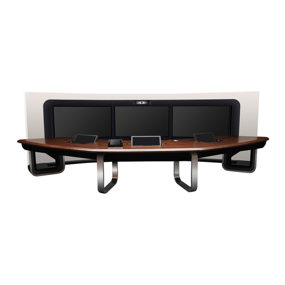
Page 73: Checking The Multi-Functional Conference Table After Installation
Step 2 The three tabletop segments are level, and the gaps between adjacent tabletop segments are small and even. For details, see 8.5 Installing the Tabletop. ----End Example Figure 8-28 shows the installed multi-functional conference table. Figure 8-28 Multi-functional conference table Issue 07 (2013-11-08) Huawei Proprietary and Confidential Copyright © Huawei Technologies Co., Ltd. -
Page 74: Installing The Second Row Of The Multi-Functional Conference Table
9.5 Install the Cable Troughs 9.6 Installing the Microphones 9.7 Installing the Multi-Functional Sockets 9.8 Installing the Tabletop Display Buttons 9.9 Checking the Multi-Functional Conference Table After Installation Issue 07 (2013-11-08) Huawei Proprietary and Confidential Copyright © Huawei Technologies Co., Ltd. -
Page 75: Parts List
All the front connecting rods are identical, as shown connecting Figure 9-2. Rear All the rear connecting rods are identical, as shown connecting Figure 9-3. Tabletop All the tabletop displays are identical. display Issue 07 (2013-11-08) Huawei Proprietary and Confidential Copyright © Huawei Technologies Co., Ltd. - Page 76 XLR cable Multi- functional socket Tabletop display button M6 x 16 Seve countersunk screw ST_3 x 40 Seve self-tapping screw M6 x 25 Seve countersunk screw Spacer Seve Issue 07 (2013-11-08) Huawei Proprietary and Confidential Copyright © Huawei Technologies Co., Ltd.
- Page 77 The tabletop segments 2 and 5 present in the TP3118 segments are removed from the TP318S. Front panel Cable trough All cable troughs are identical, as shown in Figure 9-4. Issue 07 (2013-11-08) Huawei Proprietary and Confidential Copyright © Huawei Technologies Co., Ltd.
- Page 78 M6 x 25 Seve countersunk screw Spacer Seve The following figures show some of the parts listed in Table 9-2. Figure 9-1 Steel frame Figure 9-2 Front connecting rod Issue 07 (2013-11-08) Huawei Proprietary and Confidential Copyright © Huawei Technologies Co., Ltd.
- Page 79 9 Installing the Second Row of the Multi-Functional Installation Guide Conference Table Figure 9-3 Rear connecting rod Figure 9-4 Cable trough Figure 9-5 Center table leg Figure 9-6 Right table leg Issue 07 (2013-11-08) Huawei Proprietary and Confidential Copyright © Huawei Technologies Co., Ltd.
-
Page 80: Installing The Multi-Functional Conference Table Stand
4 secured to its base along the line, as shown in Figure 9-7. Figure 9-7 Installing table leg 4 Step 4 Mount steel plate 4 on table leg 4, as shown in Figure 9-8. Issue 07 (2013-11-08) Huawei Proprietary and Confidential Copyright © Huawei Technologies Co., Ltd. - Page 81 Step Step 7 Mount steel frame 4 into the slots of steel plates 4 and 5, as show in Figure 9-9. Figure 9-9 Mounting steel frame 4 Issue 07 (2013-11-08) Huawei Proprietary and Confidential Copyright © Huawei Technologies Co., Ltd.
- Page 82 Fasten the six M6 x 16 countersunk screws to fix the rear connecting rod. Step 9 Attach the front connecting rod to table legs 4 and 5, as shown in Figure 9-11. Issue 07 (2013-11-08) Huawei Proprietary and Confidential Copyright © Huawei Technologies Co., Ltd.
- Page 83 Step 15 Secure table legs 1 and 7 to their bases. Place table legs 1 and 7 to appropriate locations. Then install the relevant components based on description in Step 6 through Step ----End Issue 07 (2013-11-08) Huawei Proprietary and Confidential Copyright © Huawei Technologies Co., Ltd.
-
Page 84: Installing The Tabletop Displays
When laying out an XLR microphone cables that comprise multiple cable segments, place the cable joints out of the cable trough of the multi-functional conference table. Otherwise, you may fail to install the trough cover (a conference table decorative part). Issue 07 (2013-11-08) Huawei Proprietary and Confidential Copyright © Huawei Technologies Co., Ltd. -
Page 85: Installing The Microphones
Ensure that the angle between the leftmost or rightmost microphone's straight edge and the adjacent tabletop display edge is 30 degrees. Figure 9-12 shows the angle between the rightmost microphone's straight edge and the adjacent tabletop display edge. Issue 07 (2013-11-08) Huawei Proprietary and Confidential Copyright © Huawei Technologies Co., Ltd. -
Page 86: Installing The Multi-Functional Sockets
For details, see 8.9 Installing the Tabletop Display Buttons. 9.9 Checking the Multi-Functional Conference Table After Installation After the multi-functional conference table is installed, verify the following: Issue 07 (2013-11-08) Huawei Proprietary and Confidential Copyright © Huawei Technologies Co., Ltd. - Page 87 The six tabletop segments are level with each other. For details, see 8.5 Installing the Tabletop. Figure 9-13 shows the installed second row of the multi-functional conference table. Figure 9-13 Second row of the multi-functional conference table Issue 07 (2013-11-08) Huawei Proprietary and Confidential Copyright © Huawei Technologies Co., Ltd.
-
Page 88: Mounting Front Panel 1
10 Mounting Front Panel 1 Mounting Front Panel 1 About This Chapter This chapter describes how to mount the lower front panels of the racks. 10.1 Parts List 10.2 Installation Procedure Issue 07 (2013-11-08) Huawei Proprietary and Confidential Copyright © Huawei Technologies Co., Ltd. -
Page 89: Parts List
Step 2 Align the screw holes of the lower front panel segment (left) and those of the left rack, and partially tighten four M6 x 16 countersunk screws into the holes. Issue 07 (2013-11-08) Huawei Proprietary and Confidential Copyright © Huawei Technologies Co., Ltd. - Page 90 Result After the lower front panel is mounted, verify that: The three segments are level with each other. No gaps or steps exist between adjacent panel segments. Issue 07 (2013-11-08) Huawei Proprietary and Confidential Copyright © Huawei Technologies Co., Ltd.
-
Page 91: Installing Telepresence Devices
11.5 Installing the Telepresence Host 11.6 Installing the Power Supply Controller 11.7 Installing the Network Switch 11.8 Installing the Wireless Router 11.9 Installing the Telepresence Codecs 11.10 Installing Active Speaker Systems Issue 07 (2013-11-08) Huawei Proprietary and Confidential Copyright © Huawei Technologies Co., Ltd. -
Page 92: Parts List
Hanging corner Several 11.2 Installation Locations Figure 11-1 shows the rear view of the device placement. NOTE Before installing the devices, print Figure 11-1 for reference during installation. Issue 07 (2013-11-08) Huawei Proprietary and Confidential Copyright © Huawei Technologies Co., Ltd. -
Page 93: Installing The Tri-Lens Camera
Before installing the tri-lens camera, power it on and verify that its video can be transmitted to the HD displays, that is, the video captured by the tri-lens camera can be viewed on the HD displays. Figure 11-2 illustrates the tri-lens camera. Issue 07 (2013-11-08) Huawei Proprietary and Confidential Copyright © Huawei Technologies Co., Ltd. - Page 94 HUAWEI TP3106&TP3118S&TP3118 Telepresence Installation Guide 11 Installing Telepresence Devices Figure 11-2 Tri-lens camera Procedure Step 1 Install the camera spacer to the rack, as shown in Figure 11-3. Issue 07 (2013-11-08) Huawei Proprietary and Confidential Copyright © Huawei Technologies Co., Ltd.
- Page 95 Step 2 With the lens oriented toward the conference area, place the tri-lens camera on the spacer. Step 3 Align the screw holes. Step 4 Fasten the four M6 x 16 countersunk screws to fix the tri-lens camera, as shown in Figure 11-4. Issue 07 (2013-11-08) Huawei Proprietary and Confidential Copyright © Huawei Technologies Co., Ltd.
-
Page 96: Installing The Pdus
Figure 11-4 Installing the tri-lens camera ----End 11.4 Installing the PDUs Context Seven power distribution units (PDUs) shown in Figure 11-5 must be installed to the racks. Figure 11-5 PDUs Issue 07 (2013-11-08) Huawei Proprietary and Confidential Copyright © Huawei Technologies Co., Ltd. -
Page 97: Installing The Telepresence Host
IP address 172.16.21.10, to configure its parameters. Figure 11-6 shows the telepresence host. Figure 11-6 Telepresence host Procedure Step 1 Install the securing tabs, as shown in Figure 11-7. Issue 07 (2013-11-08) Huawei Proprietary and Confidential Copyright © Huawei Technologies Co., Ltd. - Page 98 You need to install one audio processing board for both the TP3118 and TP3118S telepresence hosts. Loosen the screws in the baffle, as shown in Figure 11-8. Issue 07 (2013-11-08) Huawei Proprietary and Confidential Copyright © Huawei Technologies Co., Ltd.
- Page 99 Remove the baffle, as shown in Figure 11-9. Figure 11-9 Removing the baffle Insert the audio processing board into the correct slot, as shown in Figure 11-10. Issue 07 (2013-11-08) Huawei Proprietary and Confidential Copyright © Huawei Technologies Co., Ltd.
- Page 100 HUAWEI TP3106&TP3118S&TP3118 Telepresence Installation Guide 11 Installing Telepresence Devices Figure 11-10 Installing the audio processing board Tighten screws, as shown in Figure 11-11. Issue 07 (2013-11-08) Huawei Proprietary and Confidential Copyright © Huawei Technologies Co., Ltd.
- Page 101 HUAWEI TP3106&TP3118S&TP3118 Telepresence Installation Guide 11 Installing Telepresence Devices Figure 11-11 Tightening screws Lock the level of the audio processing board into place, as shown in Figure 11-12. Issue 07 (2013-11-08) Huawei Proprietary and Confidential Copyright © Huawei Technologies Co., Ltd.
- Page 102 You need to install one audio interface board for the TP3118S and two for the TP3118. Loosen the screws in the baffle, as shown in Figure 11-13. Issue 07 (2013-11-08) Huawei Proprietary and Confidential Copyright © Huawei Technologies Co., Ltd.
- Page 103 HUAWEI TP3106&TP3118S&TP3118 Telepresence Installation Guide 11 Installing Telepresence Devices Figure 11-13 Loosening the screws in the baffle Remove the baffle, as shown in Figure 11-14. Issue 07 (2013-11-08) Huawei Proprietary and Confidential Copyright © Huawei Technologies Co., Ltd.
- Page 104 HUAWEI TP3106&TP3118S&TP3118 Telepresence Installation Guide 11 Installing Telepresence Devices Figure 11-14 Removing the baffle Insert the audio interface board into the correct slot, as shown in Figure 11-15. Issue 07 (2013-11-08) Huawei Proprietary and Confidential Copyright © Huawei Technologies Co., Ltd.
- Page 105 HUAWEI TP3106&TP3118S&TP3118 Telepresence Installation Guide 11 Installing Telepresence Devices Figure 11-15 Installing the audio interface board Tighten screws, as shown in Figure 11-16. Issue 07 (2013-11-08) Huawei Proprietary and Confidential Copyright © Huawei Technologies Co., Ltd.
- Page 106 HUAWEI TP3106&TP3118S&TP3118 Telepresence Installation Guide 11 Installing Telepresence Devices Figure 11-16 Tightening screws Lock the level of the audio interface board into place, as shown in Figure 11-17. Issue 07 (2013-11-08) Huawei Proprietary and Confidential Copyright © Huawei Technologies Co., Ltd.
-
Page 107: Installing The Power Supply Controller
Step 6 Tighten the screws to secure the telepresence host. ----End 11.6 Installing the Power Supply Controller Context Figure 11-18 shows the power supply controller. Figure 11-18 Power supply controller Issue 07 (2013-11-08) Huawei Proprietary and Confidential Copyright © Huawei Technologies Co., Ltd. -
Page 108: Installing The Network Switch
Before installing the wireless router, power it on and verify that you can log in to its Web interface, using the default IP address 172.16.21.64, to configure its parameters. Figure 11-20 shows the wireless router. Figure 11-20 Wireless router Issue 07 (2013-11-08) Huawei Proprietary and Confidential Copyright © Huawei Technologies Co., Ltd. -
Page 109: Installing The Telepresence Codecs
HD displays, that is, the home screens of the telepresence codecs can be viewed on the HD displays. Figure 11-22 shows the telepresence codec. Issue 07 (2013-11-08) Huawei Proprietary and Confidential Copyright © Huawei Technologies Co., Ltd. -
Page 110: Installing Active Speaker Systems
11.10 Installing Active Speaker Systems Context The telepresence system has two active speaker systems, each comprising one speaker host and one pair of speakers. Figure 11-23 shows the active speaker system. Issue 07 (2013-11-08) Huawei Proprietary and Confidential Copyright © Huawei Technologies Co., Ltd. - Page 111 6 before starting the telepresence system. Procedure Step 1 Locate the DIP switch (enclosed in the red box shown in Figure 11-24) on the back of the main speaker. Issue 07 (2013-11-08) Huawei Proprietary and Confidential Copyright © Huawei Technologies Co., Ltd.
- Page 112 Step 5 Align the front sides of the speaker hosts with the cooling holes of the rear panel, and place the speaker hosts to the left and right speaker chairs respectively. Issue 07 (2013-11-08) Huawei Proprietary and Confidential Copyright © Huawei Technologies Co., Ltd.
- Page 113 NOTE Place two speakers into the center rack and one into each of the left and right racks. ----End Issue 07 (2013-11-08) Huawei Proprietary and Confidential Copyright © Huawei Technologies Co., Ltd.
-
Page 114: Mounting Front Panel 2
12 Mounting Front Panel 2 Mounting Front Panel 2 About This Chapter This chapter describes how to mount the racks' upper and side front panels. 12.1 Parts List 12.2 Installation Procedure Issue 07 (2013-11-08) Huawei Proprietary and Confidential Copyright © Huawei Technologies Co., Ltd. -
Page 115: Parts List
Step 2 The installation method for the left and right front panel segments is the same. The following procedure uses the right front panel segment as an example. See Figure 12-1. Issue 07 (2013-11-08) Huawei Proprietary and Confidential Copyright © Huawei Technologies Co., Ltd. - Page 116 Fasten three M6 x 16 countersunk screws to secure the right front panel segment to the side mounting frame. ----End Result After the lower front panel is mounted, ensure that: All panel segments are level with each other. Issue 07 (2013-11-08) Huawei Proprietary and Confidential Copyright © Huawei Technologies Co., Ltd.
- Page 117 12 Mounting Front Panel 2 No gaps or steps exist between adjacent panel segments. No gaps exist between the upper front panel, lower front panel, and HD displays. Issue 07 (2013-11-08) Huawei Proprietary and Confidential Copyright © Huawei Technologies Co., Ltd.
-
Page 118: Installing The Front Panel Decorative Parts
13 Installing the Front Panel Decorative Parts Installing the Front Panel Decorative Parts About This Chapter This chapter describes how to install the front panel decorative parts. 13.1 Parts List 13.2 Installation Procedure Issue 07 (2013-11-08) Huawei Proprietary and Confidential Copyright © Huawei Technologies Co., Ltd. -
Page 119: Parts List
CAUTION For the second row of the multi-functional conference table, install a cable trough around the right table leg only. Issue 07 (2013-11-08) Huawei Proprietary and Confidential Copyright © Huawei Technologies Co., Ltd. - Page 120 Place the decorative parts in the cable trough. Secure the decorative parts to the cable trough using two M6 x 25 countersunk screws, as shown in Figure 13-2. Issue 07 (2013-11-08) Huawei Proprietary and Confidential Copyright © Huawei Technologies Co., Ltd.
- Page 121 Figure 13-2 Installing cable trough decorative parts CAUTION For the TP3106, skip Step Step 2 Install the center decorative part to the rack bottoms, as shown in Figure 13-3. Issue 07 (2013-11-08) Huawei Proprietary and Confidential Copyright © Huawei Technologies Co., Ltd.
- Page 122 Insert two wood bolts into the location holes from the top down to secure the decorative parts. Step 3 Install the left and right decorative parts to the bottom of the racks. For details, see Step Issue 07 (2013-11-08) Huawei Proprietary and Confidential Copyright © Huawei Technologies Co., Ltd.
- Page 123 The following procedure uses the right cable trough decorative part as an example. See Figure 13-4. Figure 13-4 Installing the left cable trough decorative part ----End Issue 07 (2013-11-08) Huawei Proprietary and Confidential Copyright © Huawei Technologies Co., Ltd.
-
Page 124: Installing The Rear Panel
14 Installing the Rear Panel Installing the Rear Panel About This Chapter This chapter describes how to install the rear panel. 14.1 Parts List 14.2 Installation Procedure Issue 07 (2013-11-08) Huawei Proprietary and Confidential Copyright © Huawei Technologies Co., Ltd. -
Page 125: Parts List
The rear panel must be installed in the following order, as shown Figure 14-1: Leftmost and rightmost rear panel segments. Left center and right center rear panel segments. Five center rear panel segments. Issue 07 (2013-11-08) Huawei Proprietary and Confidential Copyright © Huawei Technologies Co., Ltd. - Page 126 Step 1 The installation method for the leftmost and rightmost rear panel segments is the same. The following procedure uses the rightmost rear panel segment as an example. See Figure 14-2. Issue 07 (2013-11-08) Huawei Proprietary and Confidential Copyright © Huawei Technologies Co., Ltd.
- Page 127 Step 2 The installation method for the left center and right center rear panel segments is the same. The following procedure uses the right center rear panel segment as an example. See Figure 14-3. Issue 07 (2013-11-08) Huawei Proprietary and Confidential Copyright © Huawei Technologies Co., Ltd.
- Page 128 Step 3 Install the five center rear panel segments. The following procedure uses the panel segment next to the right center rear panel segment as an example. See Figure 14-4. Issue 07 (2013-11-08) Huawei Proprietary and Confidential Copyright © Huawei Technologies Co., Ltd.
- Page 129 Step 4 Attach the hook-and-loop fasteners to the seams between adjacent panel segments from the top down, with the end of the hook-and-loop fastener level with the top of the panel segment, as shown in Figure 14-5. Issue 07 (2013-11-08) Huawei Proprietary and Confidential Copyright © Huawei Technologies Co., Ltd.
- Page 130 ----End Result After installation, ensure that: The gaps between adjacent panel segments are even and about 10 mm wide. The hook-and-loop fasteners are smooth without any folds. Issue 07 (2013-11-08) Huawei Proprietary and Confidential Copyright © Huawei Technologies Co., Ltd.
-
Page 131: Installing The Multi-Functional Conference Table Decorative Parts
This chapter describes how to install the multi-functional conference table decorative parts. The installation method is the same for the front row and the second row. 15.1 Parts List 15.2 Installation Procedure Issue 07 (2013-11-08) Huawei Proprietary and Confidential Copyright © Huawei Technologies Co., Ltd. -
Page 132: Parts List
The installation method is the same for the front row and the second row. The following procedure uses the front row of the multi-functional conference table as an example. Install the decorative parts in the following order: Issue 07 (2013-11-08) Huawei Proprietary and Confidential Copyright © Huawei Technologies Co., Ltd. - Page 133 Step 2 The method for installing the inner decorative parts to the left and right table legs is the same. The following procedure uses the right table leg as an example. See Figure 15-2. Issue 07 (2013-11-08) Huawei Proprietary and Confidential Copyright © Huawei Technologies Co., Ltd.
- Page 134 Secure the inner decorative part with six M6 x 25 countersunk screws. Step 3 Install the decorative parts on the front side of the center conference table, as shown in Figure 15-3. Issue 07 (2013-11-08) Huawei Proprietary and Confidential Copyright © Huawei Technologies Co., Ltd.
- Page 135 Step 4 Partially tighten 12 M6 x 16 countersunk screws into the holes on the front decorative panel (left). Step 5 Secure the front decorative panel (left) to the front decorative panel (center) with screws, as shown in Figure 15-4. Issue 07 (2013-11-08) Huawei Proprietary and Confidential Copyright © Huawei Technologies Co., Ltd.
- Page 136 15 Installing the Multi-Functional Conference Table Installation Guide Decorative Parts Figure 15-4 Securing the connecting piece Step 6 Secure the front decorative panel (left), as shown in Figure 15-5. Issue 07 (2013-11-08) Huawei Proprietary and Confidential Copyright © Huawei Technologies Co., Ltd.
- Page 137 Step 8 Install the decorative parts on the rear side of the center conference table, as shown in Figure 15-6. Issue 07 (2013-11-08) Huawei Proprietary and Confidential Copyright © Huawei Technologies Co., Ltd.
- Page 138 Figure 15-7 Installing the rear decorative part (left) Align the screw holes, and partially tighten the 10 M6 x 25 countersunk screws on the rear panel (left). Issue 07 (2013-11-08) Huawei Proprietary and Confidential Copyright © Huawei Technologies Co., Ltd.
- Page 139 Result Figure 15-8 shows the multi-functional conference table after the decorative parts have been installed. Figure 15-8 Multi-functional conference table after the decorative parts have been installed Issue 07 (2013-11-08) Huawei Proprietary and Confidential Copyright © Huawei Technologies Co., Ltd.
-
Page 140: Installing The Top Cooling Plates
16 Installing the Top Cooling Plates Installing the Top Cooling Plates About This Chapter This chapter describes how to install the top cooling plates. 16.1 Parts List 16.2 Installation Procedure Issue 07 (2013-11-08) Huawei Proprietary and Confidential Copyright © Huawei Technologies Co., Ltd. -
Page 141: Parts List
Step 1 The installation method for the leftmost and rightmost cooling plates is the same. The following procedure uses the rightmost cooling plate as an example. See Figure 16-1. Issue 07 (2013-11-08) Huawei Proprietary and Confidential Copyright © Huawei Technologies Co., Ltd. - Page 142 Step 2 The installation method for the left center and right center cooling plates is the same. The following procedure uses the right center cooling plate as an example. See Figure 16-2. Issue 07 (2013-11-08) Huawei Proprietary and Confidential Copyright © Huawei Technologies Co., Ltd.
- Page 143 Step 3 Install the center cooling plates. For details, see Step Step 4 Fine-tune the cooling plates until, using visual inspection, the gaps between them are adjusted even. Then fully tighten all screws. ----End Issue 07 (2013-11-08) Huawei Proprietary and Confidential Copyright © Huawei Technologies Co., Ltd.
- Page 144 Packing case number, which is the unpacking order Table 17-1 Center rack packing case Packi Sub- Name Quantit Reference Chapter Packin Case g Case Numbe Center rack TP3106 Screw Accessory Issue 07 (2013-11-08) Huawei Proprietary and Confidential Copyright © Huawei Technologies Co., Ltd.
- Page 145 Name Quantit Remarks Packing Case Case Numbe Fixture TP3106 Table 17-5 Table leg packing case Packi Sub- Name Quantit Remarks Packing Case Case Numbe Table leg TP3106 Issue 07 (2013-11-08) Huawei Proprietary and Confidential Copyright © Huawei Technologies Co., Ltd.
- Page 146 Tabletop display panel Table 17-7 Front panel packing case Packi Sub- Name Quantity Remarks Packin Case g Case Numb Front panel TP3106 (center) Accessory and screw Issue 07 (2013-11-08) Huawei Proprietary and Confidential Copyright © Huawei Technologies Co., Ltd.
- Page 147 Table 17-10 Multi-functional conference table cable trough packing case Packi Sub- Name Quantity Remarks Packin Case g Case Numb Left cable trough 1 TP3106 Right cable trough Issue 07 (2013-11-08) Huawei Proprietary and Confidential Copyright © Huawei Technologies Co., Ltd.
- Page 148 Table 17-13 Second-row steel frame packing case Packi Sub- Name Quantity Remarks Packin Case g Case Numb Table leg TP3118S Multi-functional TP3118S conference table stand Issue 07 (2013-11-08) Huawei Proprietary and Confidential Copyright © Huawei Technologies Co., Ltd.
- Page 149 Screws and TP3118S accessories Table 17-16 Second-row decorative part packing case Packi Sub- Name Quantity Remarks Packin Case g Case Numb Multi-functional TP3106 conference table decorative part Accessories Issue 07 (2013-11-08) Huawei Proprietary and Confidential Copyright © Huawei Technologies Co., Ltd.
- Page 150 Table 17-19 Second-row multi-functional conference table packing case Packi Sub- Name Quantity Remarks Packin Case g Case Numb Cable trough TP3118S Multi-functional TP3118S conference table decorative part Issue 07 (2013-11-08) Huawei Proprietary and Confidential Copyright © Huawei Technologies Co., Ltd.
- Page 151 17 Parts List Sorted by Packing Case Table 17-20 Second-row multi-functional conference table packing case Packi Sub- Name Quantity Remarks Packin Case g Case Numb Cable trough TP3106 Multi-functional conference table decorative part Issue 07 (2013-11-08) Huawei Proprietary and Confidential Copyright © Huawei Technologies Co., Ltd.
- Page 152 Used for securing curved connecting rods to the racks. ST_3 x 40 self- Length: 40 mm. tapping screw Used for securing steel frames and tabletop segments. Issue 07 (2013-11-08) Huawei Proprietary and Confidential Copyright © Huawei Technologies Co., Ltd.