Table of Contents
Advertisement
Overview of Equipment
Front side of the receiver
Rear side of the receiver
Remote control
Overview of Equipment
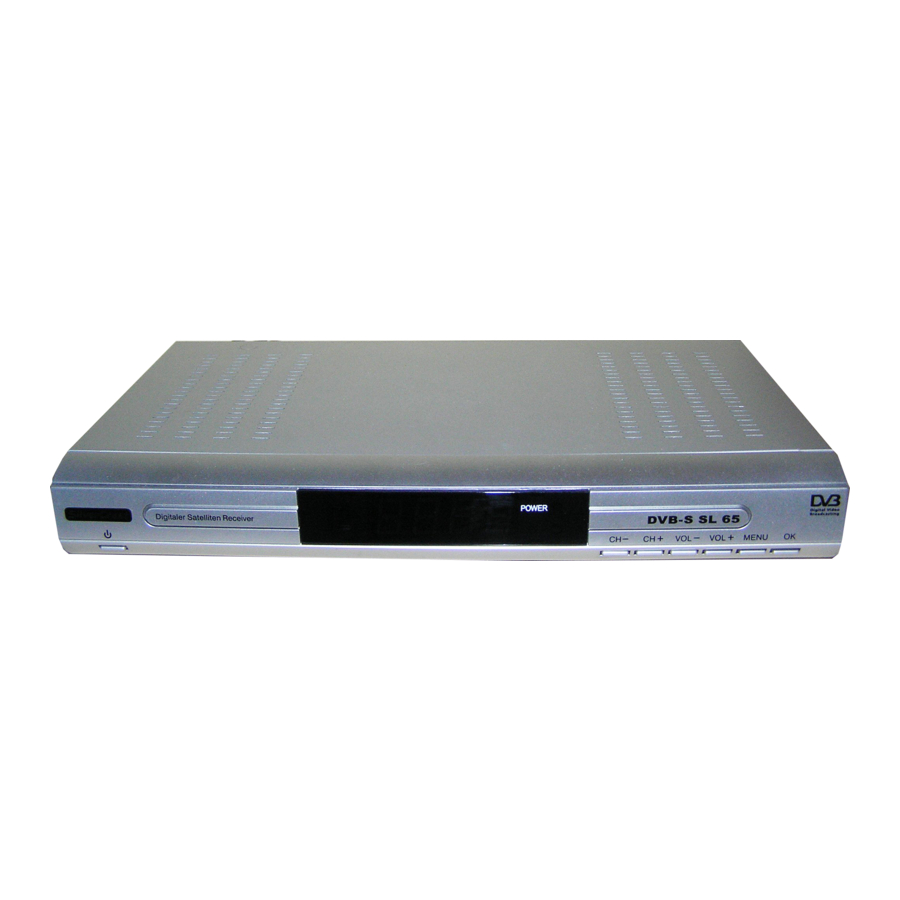
Front side of the receiver
1
LED display
Shows channel location or ttime
2
–
Infrared sensor for the signal of the remote control
3
LED POWER
LED is illuminated if the receiver is switched on or in
standby mode
4
OK
Confi rm
5
MENU
Invokes main menu
6
VOL +
Increases volume
Cursor moves to the right
7
VOL –
Decreases volume
Cursor moves to the left
8
CH +
Switches to the next higher channel location
Cursor moves up
9
CH –
Switches to the next lower channel location
Cursor moves down
10 POWER
Switches on and switches to the standby mode
Rear side of the receiver
1
RF OUT
LNB connection for a second satellite receiver
2
LNB IN
LNB connection for the antenna cable
3
VCR
SCART connection for the video set
4
TV
SCART connection for the TV set
5
100 – 240 V~
Mains connection
50/60 Hz, 30 W
6
0/1
Mains switch
7
S-VHS
S-Video connection
8
COAXIAL
Digital coaxial audio output
9
OPTICAL
Digital optical audio output
10 RS 232
Serial port
11 VIDEO
Analog video connection
12 AUDIO L
Left analog audio connection
13 AUDIO R
Right analog audio connection
Advertisement
Table of Contents

Related Manuals for Silvercrest SL 65


Summary of Contents for Silvercrest SL 65
-
Page 1: Overview Of Equipment
Overview of Equipment Overview of Equipment Front side of the receiver Front side of the receiver LED display Shows channel location or ttime – Infrared sensor for the signal of the remote control LED POWER LED is illuminated if the receiver is switched on or in standby mode Confi... - Page 2 Remote control POWER Switches on and switches to the standby mode ZOOM Enhances the TV image LIST Shows favourits list (groups) TIMER Timer TEXT Teletext MUTE Turns off sound Without function Increases volume/cursor moves to the right Confi rms menu or menu item 10 CH q Switches to the next lower channel location / cursor moves down...
- Page 3 Digital Satellite Receiver SL 65 Operating Manual Version 1, as of 03.05.2005...
-
Page 4: Preface
Preface This operating manual will help you in the • appropriate, • safe and • favorable usage of the digital satellite receiver, in short, the ”receiver”. We assume that the user of the receiver has overall knowledge regarding the handling of audio and video equipment. Each person who •... -
Page 5: Table Of Contents
Contents Preface ....................2 Style Features ................... 2 Contents .................... 3 Safety Instructions ................5 Basic Safety Instructions ..............5 Explanation of Safety Instructions ............7 Appropriate Usage................7 Scope of Supply................8 Description ..................9 Connecting the Receiver..............12 LNB cable installation ............... - Page 6 DiSEqC motor setting ............... 40 Boot channel..................40 Company Setting ................40 Acoustic signal for the orientation of the satellite antenna ....40 Software upgrade via satellite ............41 Games ....................41 Keys with special functions ............42 EPG mode ..................42 Timer....................
-
Page 7: Safety Instructions
Safety Instructions Please read the safety instructions carefully before operating the receiver. Please follow all warnings and instructions on the equipment and in the operating manual. Basic Safety Instructions Electrical connection • Do not expose the receiver to rain as well as any kind of humidity to avoid risk of fire and electric shock. - Page 8 • Disconnect the receiver from the power source in case of operational disruptions. Suitable location • Place the receiver on a stable and even base. • Avoid proximity to: heat sources, like e. g. heaters, naked flames, like e. g. candles, devices with strong magnetic fields, like e.
-
Page 9: Explanation Of Safety Instructions
Appropriate Usage The digital satellite receiver SL 65 receives digital channels in a covered area. It is exclusively meant for this purpose and should only be used for the same. This also includes paying attention to all information in this operating manual especially that of safety instructions. -
Page 10: Scope Of Supply
Scope of Supply Check the scope of supply after purchase. The scope of supply may vary according to the type of the receiver. Please follow the information on the packaging. Pieces Description Digital Satellite Receiver SL -65 Remote control 2 batteries type LR 03/AAA/1,5 V SCART cable... -
Page 11: Description
Description With this receiver, you are able to receive digital satellite channels via a satellite antenna. You need not program the receiver. The most common broadcasting stations of the mostly used satellites are pre-programmed. You can receive the channels broadcasted through these satellites as soon as you have connected the receiver to a satellite antenna and oriented it to one of these satellites. - Page 12 The receiver gets a firmware update program through the Astra 19° satellite. Other features of the equipment: • OSD languages: German, English, French, Turkish, Polish, Greek, Hungarian, Spanish, Czech, Italian, and Dutch • Software update via satellite Astra 19° or RS232 connection •...
- Page 13 • Loop-through function for the connection of an analogue receiver, (F connection, loop through) • Super Fast Videotext with a memory of 800 pages • Radio reception, background image for radio • Channel information on the screen, current time • DiSEqC 1.0, 1.2, Goto X is supported if an appropriate antenna unit is connected •...
-
Page 14: Connecting The Receiver
Connecting the Receiver The receiver is connected by means of an LNB cable with the connector box of your satellite antenna. You must install the LNB cable before connecting the receiver, if necessary. The LNB cable is not included in the scope of supply. Caution! Connect the receiver to the mains only after you have connected it to all equipment and the antenna properly. - Page 15 Installation diagram...
-
Page 16: Connection With The Scart Cable
Connection with the SCART cable Fasten the IF-connector of the LNB cable onto the “LNB IN“ antenna connection on the receiver. Insert the SCART cable in the SCART socket “TV” on the receiver. Connect the SCART cable to the TV set. Follow the operating manual of the TV set. - Page 17 Connection diagram...
-
Page 18: Connection With The Yuv Cable
Connection with the YUV cable If you own a TV set with YUV connections, you can connect it via the SCART socket “TV“ to the receiver. For this purpose, you need a YUV cable with YUV connectors at one and a SCART connector at the other extreme. - Page 19 Connection diagram...
-
Page 20: Connection With The S-Video Cable (S-Vhs)
Connection with the S-Video Cable (S-VHS) Caution! Strictly follow instructions for connecting the S-video cable (SVHS) given in the operating manual of your TV set. The S-Video cable is not included in the scope of supply. Insert the S-Video cable in the “S-Video“ socket on the receiver. Connect the S-Video cable to the TV set. - Page 21 Connection diagram...
-
Page 22: Connection With The Cinch Cable
Connection with the Cinch cable If you own a TV set not provided with a SCART socket, you can connect the receiver via a Cinch cable. Connect the “VIDEO“ socket on the receiver to the video input of the TV set. Connect the “AUDIO-R“... - Page 23 Connection diagram...
-
Page 24: Connection Of An Audio-Digital Receiver
Connection of an Audio-Digital Receiver If you want to use 5-channel audio transmission (Dolby digital sound/AC3), you must connect your audio-digital receiver to the optical or coaxial output of the receiver. Caution! Never connect the Phono input of your stereo system to the receiver;... - Page 25 Connection of the coaxial digital output Insert the coaxial cable in the “COAXIAL” socket on the receiver. Connect the coaxial cable to the audio-digital receiver. Connection diagram...
- Page 26 Connection of the optical digital output Pull the protective cap out of the "OPTICAL“ socket on the receiver. Insert the optical cable in the “OPTICAL” socket on the receiver. Connect the optical cable to the audio-digital receiver. Connection diagram...
-
Page 27: Operation
Operation Remote control Two Micro type batteries are required for the remote control: LR 03/AAA/1.5 V Open the battery compartment. Insert two batteries according to polarities mentioned on the battery compartment. Push the cover of the battery compartment carefully till the cover is locked. Replace discharging batteries on time. -
Page 28: Receiver
Receiver Caution! Check that connections of all equipment and the antenna are proper before connecting the receiver to the mains. Insert the mains plug of the receiver in the mains socket. The device is in standby mode. The numerical display of the receiver is not illuminated (display dark). -
Page 29: Operation
Operation User interface on the TV monitor You can do individual settings of your receiver using the menus in the user interface. You must switch on the receiver and the TV set to view the user interface. It consists of main menus and their sub- menus. -
Page 30: Screen-Inlays While Switching A Channel
Screen-Inlays while Switching a Channel When a channel is switched, an information bar is inlayed on the screen for 5 seconds. In this information bar, you will find the following indications: Date Current time Audio language Channel location Received channel The satellite through which signals are received TXT symbol “TXT“... -
Page 31: Menu Structure
Menu Structure Main menu Sub-menu Description Channel Channel assignation See following text Manager Channel groups See following text Sort channels See following text New channel Setup of new channels Edit channels Editing of PID channels Delete All See following text System Add satellite Adding satellites manually... -
Page 32: Menu Navigation
Main menu Sub-menu Description Other Games See following text Signal display Information on satellite and signal strength Serial update Activate RS232 Satellite update Software update via satellite Astra 19,2° East Keyboard layout Help texts on the functions of some keys on the remote control Version Information on hardware and software of the receiver... - Page 33 Press the “CH " and “CH L "arrow keys to switch from one setting to the next one. The selected setting is marked in yellow. Press the “OK“ key to confirm the marked setting. You can: switch between the options by using the arrow keys “V+" or “V–" mark the desired option with the arrow keys “CH "and “CH L "...
-
Page 34: Edit Channel List
Edit channel list For editing the channel list, go to the sub-menu “Channel assignation“ (via Menu, Channel admin.) The beginning of the list of available channels is displayed. Further information on a marked channel is displayed which can be modified. Option Description 1.Fav... -
Page 35: Favorites List, Channel Groups
Favorites list, channel groups To create or edit the favorites list, go to the sub-menu ”Channel groups“. The list of available TV channels is displayed. By means of the numeric keys you can assign each channel to a group (favorites list): •... -
Page 36: Sort Channels
Sort channels Go to the sub-menu "Sort channels" to sort the channels. You can sort channels automatically according to different criteria, e.g. alphabetic. Select a criterion and confirm the input with the “OK” key. Channels are sorted as per this criterion accordingly. For carrying out a manual sorting of the channels, select: “Menu“... -
Page 37: Start Scan Of Broadcasting Stations
Start scan of broadcasting stations Select the menu item, “Edit satellite“ in the “System installation“ menu. Press the ”OK” key. Select the desired satellite. Select the search criterion in "Channel type". We recommend using the option "uncoded". Press the ”OK” key. Respond to the query “Start scan“... -
Page 38: Add A New, Not Pre-Programmed Satellite And Run A Scan On It
Add a new, not pre-programmed satellite and run a scan on it Adding a new satellite Press the ”MENU” key. Select the sub-menu “Add satellite“ in the menu “System installation“. Press the ”OK” key. A small menu will be displayed on the screen. Press the ”V+”... -
Page 39: Change System Setup
Scan on the new satellite Select the sub-menu “Automatic scan“ in the menu “System installation“. Press the ”OK” key. Press the ”V+” key. The new satellite will be displayed in a small menu on the screen. Select the new satellite. Now, you will see the satellite frequency assignation. - Page 40 TV set Video mode: Auto, PAL-M, PAL-BG, NTSC, Secam 4:3 Letterbox, normal format 4:3 PanScan, full image height with aspect ratio 4:3, wide screen with 16:09 Set video output: CVBS, RGB, YcbCr (YUV) HF mode: without function HF channel: without function Set brightness of the TV image Set contrast of the TV image Time...
-
Page 41: Pin Code / Child Lock
Please note: The lower information bar in the screen menus shows you which keys you can use. Make the desired settings. PIN code / child lock In this menu, you can block the key functions of the device. You can modify the PIN code (password) set by the company and enter any other four-digit number as a personal PIN code. -
Page 42: Diseqc Motor Setting
DiSEqC motor setting (via “Menu“ key, System configuration) Select the menu item, “DiSEqC motor setting” in the menu “System configuration” for doing DiSEqC motor settings. You can carry out changes only if you have connected the receiver to a motorized satellite system. Boot channel (via “Menu“... -
Page 43: Software Upgrade Via Satellite
Software upgrade via satellite Please note: the update has nothing to do with the storage of TV channels. It is rather meant to update the system software of the receiver. Normally, the update is not required for a trouble-free operation of the receiver. -
Page 44: Keys With Special Functions
Keys with special functions EPG mode In this mode, you can obtain information on the current program. Press the ”EPG” key during normal operation. On the left appears the list of broadcasting stations and on the right current information on the selected program. By pressing the “EPG“... -
Page 45: Timer
Timer (Via the “Timer“ key). In this menu you can set up to eight different timers. The receiver will then switch on the TV set at the determined time. You have following setting options: Option Description Timer number Set timer number from 1 to 8 Timer mode Set interval: off, once, daily, weekly, monthly, annually Wakeup mode... -
Page 46: Audio
Audio With the Audio key, you can select the audio track if a broadcasting station offers multi-channel sound. Additionally, you can activate the Dolby Digital mode here (For this purpose you additionally need a Dolby Digital system. The connection is made on the rear of the device via the COAXIAL or OPTICAL socket). -
Page 47: Tv/Radio
TV/Radio With the “TV/Radio“ key (key on the remote control: TV/?) you can switch between TV and radio functions. Press the “TV/Radio“ key as long as you have set the desired function. Now, the receiver transmits a radio program and shows a background image. -
Page 48: Fav
Press the ”Fav” key. The screen shows the previously defined favorites list. Select a channel from the favorites list. Press the “OK“ key to confirm the selection. Uninstalling the receiver Disconnect the receiver and connected equipment from the power supply. Loosen the LNB cable from the receiver. -
Page 49: Troubleshooting
Troubleshooting Symptom Possible cause and remedy The numerical display The power cable is not connected. of the receiver is not Connect the power pack to the mains socket. illuminated and there Connect the main switch. is no sound or image Frontal display dark The receiver is in the standby mode. -
Page 50: Disposal
The remote control Batteries are exhausted. does not work Replace the batteries with new ones. Remote control is not directed properly. Aim the remote control towards the front side of the receiver and ensure that there is no obstacle between the remoter control and the receiver. -
Page 51: Technical Specifications
Technical Specifications Receiver Dimensions in mm (W × D × H) 280 × 170 × 45 Input frequency range 950 MHz ~ 2150 MHz IF band width 55 MHz / 8 MHz (below 5MS/s) LNB power supply 13/18 GS, 0,35 A max. Overload protection LNB control 22 KHz ±... -
Page 52: Manufacturer
+49 7161 503006 11 Website: www.comag-ag.de Service hotline +49 7161 503006 33, e-mail: hotline@comag-ag.de Guarantee The guarantee for the digital satellite receiver SL 65 of Comag is in conformity with the prevailing statutory regulations at the time of purchasing the product. -
Page 53: Declaration Of Conformity
Guideline for low voltage, 73/23/EEC • EN 60 335-1, EN 60 335-2-15 Guideline for electromagnetic compatibility, 89/336/EEC • EN 55 013 • EN 55,020 • EN 61,938 Equipment type /model: Digital Satellite Receiver SL 65... -
Page 54: Glossary
Glossary Alternating Current Connection for alternating current Direct Current Connection for direct current Cinch Coaxial connector for connecting TV set or stereo system. connector DiSEqC Digital Satellite Equipment Control Digital system, with which the receiver can control different components of the external unit. It is especially used for selecting from multiple satellite positions (for example Astra and Eutelsat). - Page 55 Receiver Receiver unit, which converts signals from the antenna to video and audio signals. SCART A 21-pole connector for connecting the TV set to the receiver. Swap function Invokes the last-set channel Transponder Transmission channel of a satellite Abbreviation for Video Cassette Recorder. YUV is a signal formed by one brightness (Y) and two color difference signals (UV).