Huawei RP200 Room Presence Installation Manual
Hide thumbs
Also See for RP200 Room Presence:
- Commissioning manual (99 pages) ,
- Installation manual (49 pages) ,
- Quick operation manual (2 pages)

Related Manuals for Huawei RP200 Room Presence


Summary of Contents for Huawei RP200 Room Presence
- Page 1 RP100 and RP200 Room Presence Installation Guide Issue: 07 Part number: 31043853 Date: 2021-04-20 HUAWEI TECHNOLOGIES CO., LTD.
-
Page 2: Table Of Contents
-------------------------------------------------------------------------------------------------------- - --------------- - --------------- - --------------- - --------------- - --------------- - --------------- - --------------- - --------------- - --------------- - --------------- - --------------- - --------------- - --------------- - --------------- - --------------- - --------------- - --------------- - --------------- - --------------- - --------------- - --------------- - --------------- - --------------- - --------------- - --------------- - --------------- - --------------- - --------------- - --------------- - --------------- - --------------- - --------------- - --------------- - --------------- - --------------- - --------------- - ---------------- - --------------- - --------------- - --------------- - --------------- - --------------- - --------------- - --------------- - --------------- - --------------- - --------------- - --------------- - --------------- - --------------- - --------------- - --------------- - - Copyright © Huawei Technologies Co., Ltd. 2019. All rights reserved. - Page 3 Contents 10 Installing the RP100 Display ------------------------------------------------------------------------------------------------------------------------------------------------------------------------------------------------------------------------------------------------------------------------------------------------------------------------------------------------------------------------------------------------------------------------------------------------ 10.1 Removing the Camera Spacer ------------------------------------------------------------------------------- - --------------- - --------------- - --------------- - --------------- - --------------- - --------------- - --------------- - --------------- - --------------- - --------------- - --------------- - --------------- - --------------- - --------------- - --------------- - --------------- - --------------- - --------------- - --------------- - --------------- - --------------- - --------------- - --------------- - --------------- - ---------------- - --------------- - --------------- - --------------- - --------------- - --------------- - --------------- - --------------- - --------------- - --------------- - --------------- - --------------- - --------------- - --------------- - --------------- - --------------- - ------- 10.2 Installing the Display -------------------------------------------------------------------------------------- - --------------- - --------------- - --------------- - --------------- - --------------- - --------------- - --------------- - --------------- - --------------- - --------------- - --------------- - --------------- - --------------- - --------------- - --------------- - --------------- - --------------- - --------------- - --------------- - --------------- - --------------- - --------------- - --------------- - --------------- - --------------- - --------------- - --------------- - --------------- - --------------- - --------------- - --------------- - --------------- - --------------- - --------------- - ---------------- - --------------- - --------------- - --------------- - --------------- - --------------- - --------------- - --------------- - --------------- - --------------- - --------------- - --------------- - --------------- - --------------- - --------------- - ---------------...
-
Page 4: Product Introduction
1 Product Introduction RP100 and RP200 Room Presence, also known as RP, has 11 models. The following table describes the naming rules for each RP model. Model Display Model Number of Displays Endpoint and Camera • TCL-B48F360 RP100-46S TE30 • Samsung-LH48DCE •... - Page 5 1 Product Introduction The following two figures show the appearance of the RP100 and RP200, respectively. RP100-S/A Appearance TE30 or VPC600 Display RP100-65T Appearance VPT300 Display...
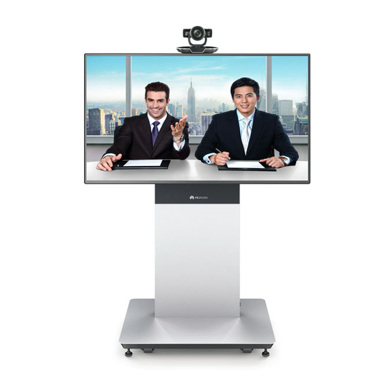
- Page 6 1 Product Introduction RP200-S/A Appearance TE30 or VPC600 Display Presentation source Video source RP200-55T Appearance VPT300 Display Video source Presentation source...
-
Page 7: Safety Precautions
2 Safety Precautions When installing the Room Presence system, follow the precautions and safety instructions in this guide. General Precautions When performing operations, obey local safety laws and regulations. The safety precautions detailed in this guide are supplementary to local safety regulations. Only trained and qualified personnel are allowed install, replace, or maintain the Room ... -
Page 8: Installation Procedure
3 Installation Procedure The RP consists of several components, such as the rack, display, HD camera, and bracket. Start Prepare installation Tools delivered with the RP are placed in the tool box on the base. tools Check the installation environment •... -
Page 9: Preparing Installation Tools
4 Preparing Installation Tools The following tools are not delivered with the RP but are necessary for its installation. Phillips screwdriver Diagonal pliers Nipper pliers Spirit level Retractable utility knife ESD gloves ESD: electrostatic discharge The following tools are delivered with the RP. M12 open-end wrench M6 hex socket wrench M6 Allen wrench... -
Page 10: Checking The Installation Environment
This section describes the requirements on power, network, illuminance, and noise. To learn more, contact Huawei engineers. NOTE To obtain this guide, visit http:www.huawei.com and search for HUAWEI RP Series Room Telepresence Decoration Suite. Power and Network The power and network requirements are as follows: At least two power sockets (220 V/10 A or 110 V/10 A) on the wall behind the rack. -
Page 11: Unpacking The Box And Checking The Items In It
You can unpack the box as long as it meets one or two items of the following requirements. If any exception occurs, contact Huawei engineers for a replacement. The box has been placed in the same area that the component is to be installed in. - Page 12 If protection foam is broken, provide close-up photos of the broken foam (including the fixture foam at the top and bottom and protection foam on the left and right). Paper carton: label photo with a clear SN (both Huawei label or original maker label are needed), photos of six faces, and ...
-
Page 13: Unpacking
Before installing the RP, check its components based on the packing list. If any component is missing or damaged, contact Huawei engineers for a replacement. The touch panel and its bracket are optional accessories. They are delivered in two boxes separately. -
Page 14: Powering On Rp Components 1
Connect the power cable and power TE30 indicator first blinks green the endpoint on. and then turns steady green. Contact Huawei It starts up properly. The engineers for a Connect the power cable and power TE50 indicator first blinks blue and replacement. -
Page 15: Cable List
7 Labeling Cables Cable List Label cables based on the cable list. RP-S Cable List To Be Cable Name Length Connected Devices Labeled Number Onsite Presentation [V01] VGA-VGA 04050165 10.0 m TE30 VGA IN video source VGA Optional presentation [V02] VGA-VGA 04050165 10.0 m... - Page 16 7 Labeling Cables Cable List RP-A Cable List To Be Cable Name Length Connected Devices Labeled Number Onsite Proprietary port- TE50 VIDEO [V01] 04050879 5.0 m VPC600 ENDPOINT Proprietary port INPUT1 HD-VI Presentation video TE50 VIDEO INPUT2 [V02] VGA-VGA 04050165 10.0 m source VGA VGA/YPbPr...
- Page 17 7 Labeling Cables Cable List RP-T Cable List To Be Cable Name Length Connected Devices Labeled Number Onsite Proprietary port- VPT300 VIDEO OUTPUT TE50 VIDEO [V01] 04050879 5.0 m Proprietary port HD-VI INPUT1 HD-VI Presentation video source TE50 VIDEO INPUT2 [V02] VGA-VGA 04050165...
-
Page 18: Securing The Rack
8 Securing the Rack DANGER The rack requires at least two people to lift or move it. Exercise caution when lifting or moving it. Use one hand to hold the rack base and the other to hold one side of the rack. Ask your partner to hold the rack in the same way on the other side. -
Page 19: Installing Components In The Rack
9 Installing Components in the Rack Removing the Panel Remove the speaker cover plate. Remove the lower front panel of the rack. Laying Rack-Embedded Cables Out The rack-embedded cables need to be laid out from the rack for subsequent connections. Check the ties of the rack-embedded Remove the rear access panel. -
Page 20: For Rp-S/T Only) Installing The Power Adapter And Integrated Cable
9 Installing Components in the Rack (For RP-S/T Only) Installing the Power Adapter and Integrated Cable Prepare the power adapter and integrated cable based on the packing list. Connect the TE30's or VPT300's power (For RP-S only) Install the TE30 power adapter to the 7-outlet PDU (located in the adapter and integrated cable into the rack and at the back of the upper front panel.) -
Page 21: Installing Speakers (For Lg-47Ls33A/Lg-55Ls33A/Lg-55Se3D Only)
9 Installing Components in the Rack Installing Speakers (for LG-47LS33A/LG-55LS33A/LG-55SE3D Only) Install the fixture provided by Huawei at Remove the speaker from its fixture the back of the speakers. provided by LG. Use a Phillips screwdriver to remove screws used to affix the speakers to the fixture. -
Page 22: Installing The Panel
9 Installing Components in the Rack Installing the Panel NOTE Before installing the panel, route all cables connected to the display out of the middle part of the upper front panel and route all cables connected to the TE30/VPC600/VPT300 out of the rear access panel. -
Page 23: Installing The Rp100 Display
10 Installing the RP100 Display DANGER The display requires at least two people to lift or move it. Exercise caution when lifting or moving it. CAUTION If you want to adjust up the RP rack, elevate it before installing the display. For details about how to elevate the rack, see steps 7 and 8 in Appendix A "Elevating the Rack."... -
Page 24: Installing The Display 2
10 Installing the RP100 Display 10.2 Installing the Display Prepare the display, single-screen bracket, cables, and screws as specified in the RP packing list. CAUTION Ensure that the cushion and ground are clean and tidy, preventing the display from being damaged by sundries such as screws. - Page 25 10 Installing the RP100 Display 10.2 Installing the Display CAUTION Place the mounting bracket onto the display gently. The display may be damaged by a heavy press. Mount the bracket at the back of the After determining the holes for mounting display.
- Page 26 10 Installing the RP100 Display 10.2 Installing the Display (For LG-47LS33A/TCL-B55F360/LG- (For Samsung-LH48DCE and Samsung- LH55DCE only) Secure the bracket by 55LS33A only) Secure the bracket by tightening the M6 x 20 cross recessed tightening the M6 x 20 cross recessed screws at the bottom.
- Page 27 10 Installing the RP100 Display 10.2 Installing the Display (For Samsung LH65QBR only) Secure (For LH48DCE/Samsung LH55DCE the bracket by tightening the M8 x 35 Display comes with M8 x 20 cross screws, cross recessed screws at the bottom. Samsung LH65QMF display comes with M8 x 25 cross screws, 55SE3KB LG- 49SE3KB/LG- display comes with M6 x 15 cross screw only) Secure the bracket by...
- Page 28 10 Installing the RP100 Display 10.2 Installing the Display (For the LG-55SE3D adjustable bracket 11-1 (For Samsung-LH48DCE only) 11-2 only) Adjust the horizontal bar vertically Adjust the bracket horizontally to "30". to "34". LG-55SE3D: Samsung-LH48DCE: adjusted to “34" adjusted to "30" 11-3 (For Samsung-LH55DCE only) (For TCL-B48F360 only) Adjust the...
- Page 29 10 Installing the RP100 Display 10.2 Installing the Display (For LG-47LS33A and LG-55LS33A only) 11-5 (For LG-49SE3KB only) Adjust the 11-6 Adjust the bracket horizontally to "LG". bracket horizontally to "24". LG-47LS33A LG-49SE3KB: LG-55LS33A: adjusted to "24" adjusted to "LG" 11-7 (For TCL-B55F360 only) Adjust the (For LG-55SE3KB only) Adjust the...
- Page 30 10 Installing the RP100 Display 10.2 Installing the Display (For Samsung-LH65QMF only) 11-9 (For Samsung-LH65QBR only) 11-10 Adjust the bracket horizontally to “55". Adjust the bracket horizontally to "70". Samsung-LH65QMF: Samsung-LH65QBR: adjusted to “55" adjusted to "70" Adjust the horizontal bars left or right so Tighten the eight M6 x 16 socket head cap that the 0 is at the center of the Display.
- Page 31 10 Installing the RP100 Display 10.2 Installing the Display Ensure that all screws are tightened. (For 47LS33A and 55LS33A only) Connect the extension power cable, extension video cable, and extension audio cable to the Display. For details, 15 Connecting Cables DANGER The Display requires at least two people to lift or move it.
-
Page 32: Installing The Rp200 Display (Method 1)
11 Installing the RP200 Display (Method 1) 11.1 Removing the Camera Spacer Remove the rear cable cover. Remove the crimping cover. Remove the camera spacer. NOTE Keep the camera spacer in a safe place for Phillips future use during the TE30/VPC600/VPT300 screwdriver installation. - Page 33 11 Installing the RP200 Display (Method 1) 11.2 Installing the Display NOTE There are two types of dual-screen brackets. For details about the simplified installation method, see Installing the RP200 Display (Method 2). Assemble the dual-screen brackets. Place the left and right brackets horizontally on the floor. The TOP arrow should point upward.
-
Page 34: Installing The Display
11 Installing the RP200 Display (Method 1) 11.2 Installing the Display CAUTION Ensure that the cushion and ground are clean and tidy, preventing the display from being damaged by sundries such as screws. To assemble the displays: 1. Lay a soft cushion on the floor and place the display on the cushion with its screen facing down. - Page 35 11 Installing the RP200 Display (Method 1) 11.2 Installing the Display (For LG-49SE3KB/LG-55SE3KB/LG-55SE3D only) Remove the LG LOGO. (For LG-49SE3KB and LG-55SE3KB only) Tighten the M6 x 15 cross recessed screws to secure the VESA adapting frames onto the back of the display.
- Page 36 11 Installing the RP200 Display (Method 1) 11.2 Installing the Display (For Samsung-LH48DCE and Samsung-LH55DCE only) Install four male/female studs respectively on the top and at the bottom of the joints between the two displays. Eight male/female studs required for connecting two Samsung-LH48DCE or Samsung-LH55DCE displays Use a pair of needle-nose pliers Install one male/female stud...
- Page 37 11 Installing the RP200 Display (Method 1) 11.2 Installing the Display Install the connecting plates. Install three connecting plates for the 47-inch/49-inch LG display/LG-55SE3D display/TCL display. - Install four connecting plates for LG-55LS33A/LG-55SE3KB. - Install two connecting plates for 48-inch Samsung-LH48DCE/55-inch Samsung-LH55DCE. Place a connecting plate to Tighten the screws of the two male/female studs.
- Page 38 11 Installing the RP200 Display (Method 1) 11.2 Installing the Display (For TCL-B48F360 only) Secure the After determining the holes for mounting 13-1 the vertical bars, push the bracket bracket by tightening the M6 x 20 cross recessed screws at the bottom. upwards and tighten the screws.
- Page 39 11 Installing the RP200 Display (Method 1) 11.2 Installing the Display 13-4 (For Samsung-LH48DCE and Samsung- (For the LG-55SE3D fixed bracket only) 13-5 LH55DCE only) Secure the bracket by Tighten the M6 x 16 socket head cap tightening the M6 x 20 cross recessed screws at the bottom.
- Page 40 11 Installing the RP200 Display (Method 1) 11.2 Installing the Display To secure the brackets, loosen the M6 x 16 16-1 (For Samsung-LH48DCE only) socket head cap screws on the brackets. Adjust the bracket horizontally to "30". CAUTION Just loosen the screws.
- Page 41 11 Installing the RP200 Display (Method 1) 11.2 Installing the Display (For Samsung-LH55DCE only) (For TCL-B48F360 only) Adjust the 16-4 16-5 Adjust the bracket horizontally to "54". horizontal bars vertically to "TCL48". TCL-B48F360: LH55DCE: adjusted to "TCL48" adjusted to "54" 16-6 16-7 (For LG-47LS33A and LG-55LS33A...
- Page 42 11 Installing the RP200 Display (Method 1) 11.2 Installing the Display (For the LG55SE3D adjustable bracket Adjust the horizontal bars left or right so 16-8 only) Adjust the horizontal bar vertically that the 0 is at the center of the Display. to "34".
- Page 43 11 Installing the RP200 Display (Method 1) 11.2 Installing the Display DANGER The display requires at least two people to lift or move it. Exercise caution when lifting or moving it. Use one hand to hold the horizontal bars of the bracket and the other to hold the bottom of the display. To prevent the connecting plates from being distorted, lift the two displays up after putting them upright.
-
Page 44: Installing The Rp200 Display (Method 2)
12 Installing the RP200 Display (Method 2) 10.2 10.1 10.1 12.1 Removing the Camera Spacer Remove the rear cable cover. Remove the crimping cover. Remove the camera spacer. NOTE Keep the camera spacer in a safe place for Phillips future use during the TE30/VPC600/VPT300 screwdriver installation. - Page 45 12 Installing the RP200 Display (Method 2) 10.1 12.2 Installing the Display Assemble the dual-screen brackets. Place the left, middle, and right brackets horizontally on the floor. Left Middle Right Insert the ends of the left and right brackets onto the middle bracket. Secure the dual-screen brackets.
-
Page 46: Installing The Display
12 Installing the RP200 Display (Method 2) 10.1 12.2 Installing the Display Install the dual-screen brackets onto the rack by securing four screws (M6x16 Phillips head hexagon upset screws). Insert the two hooks into the holes on the rack. Installation holes Hooks Tighten the screws. - Page 47 12 Installing the RP200 Display (Method 2) 10.1 12.2 Installing the Display (For LG-55SE3D only) Remove the LOGO of the LG display. (For LG-55SE3D only) Adjust the brackets. 1. Loosen the four screws on the left and right of a bracket, adjust the screws in the lower part to the position marked "20", and then tighten the screws.
- Page 48 12 Installing the RP200 Display (Method 2) 10.1 12.2 Installing the Display (For Samsung-LH55DCE only) Adjust the brackets. 1. Loosen the four screws on the left and right of a bracket, adjust the screws in the lower part to the position marked “8", and then tighten the screws. 2.
- Page 49 12 Installing the RP200 Display (Method 2) 10.1 12.2 Installing the Display (For LG-55SE3D only) Secure the two (For Samsung-LH55DCE only) Tighten the screws in hole 6 in the upper part of the two screws in hole 1 in the upper part of vertical bars, then the two screws in the the vertical bars, then the two screws in the lower part.
- Page 50 12 Installing the RP200 Display (Method 2) 10.1 12.2 Installing the Display Install the other display in the same way. If the edges of the two displays are not in the same level, loosen the screws to adjust them. After the two displays are installed, slightly adjust them to be seamlessly aligned, lock the back clamp, and tighten the screw on the back clamp.
-
Page 51: Installing The Te30/Vpc600
13 Installing the TE30/VPC600 Prepare the TE30/VPC600, camera spacer, cables, and screws as specified in the RP packing list. The TE30 and VPC600 are installed in the same way but using different connection cables. Unless otherwise specified, this section uses the TE30 as an example. Introduction to the Camera Spacer Mounting peg hole Location pillar... - Page 52 13 Installing the TE30/VPC600 CAUTION All cables connected to the TE30 or VPC600 must be sorted into the groove of the cable trough on the camera spacer. The outer edge of the TE30 or VPC600 must be level with the surface of the display. Install the TE30 onto the rack.
- Page 53 13 Installing the TE30/VPC600 Insert the TE30 cables Install the crimping cover. into the rack and pull them out from the middle Insert the crimping cover into the part of the upper front bottle gourd–shaped mounting pegs. panel. Tighten the captive screws. The yellow cable is indicative.
-
Page 54: Installing The Vpt300
14 Installing the VPT300 14.1 Assembling the VPT300 10.1 Prepare the VPT300, camera spacer, cables, and screws based on the packing list. Assemble the VPT300's base. Install two VPC600s on the VPT300 base. a. Place the VPT300 base on a flat a. -
Page 55: Securing The Vpt300 Onto The Rp Rack
12 Installing the TE30/VPC600 14 Installing the VPT300 10.1 14.2 Securing the VPT300 onto the RP Rack Introduction to the Camera Spacer Mounting peg hole Location pillar Philips head screw hole Install the camera spacer onto the base of the VPT300. Location pillar Philips head... - Page 56 14 Installing the VPT300 CAUTION All cables connected to the VPT300 must be sorted into the groove of the cable trough on the camera spacer. The outer edge of the VPT300 must be 1 cm away from the surface of the display. Install the VPT300 onto the rack.
- Page 57 14 Installing the VPT300 Install the crimping cover. DANGER When mounting the rear access panel onto the rack, Insert the crimping cover into the bottle gourd–shaped mounting pegs. watch your hands. NOTE After the installation is complete, remove the protective film from the lens of the dual-camera system.
-
Page 58: Connecting Cables
15 Connecting Cables Connect cables according to the cable labels, cable list, and connection diagram. RP-S connection diagram Display on the right (for presentation) [V04] Wall-mounted [V05] power outlet TE30 4-in-1 cable [P04] [A01] [P01] [P07] [N01] [P06] [P03] [P02] Power box Power (embedded) - Page 59 15 Connecting Cables After connecting cables for the RP100-S or RP200-S, secure the excess part of the cables to the mounting bracket using cable ties, as shown in the following figures. The figures are for reference only. Bind the cables as required. RP100-S HDMI Power...
- Page 60 15 Connecting Cables Audio, video, and power cable connections of the RP100-A Wall-mounted power outlet [P01] [P02] [P03] [P04] Power box (embedded) (embedded) [P05] Display (presentation) Presentation display or projector [V04] [V03] TE50 [A02] [V01] [V02] [N01] [A01] Wall-mounted network port Presentation audio source VPM220 microphone array Presentation audio source...
- Page 61 15 Connecting Cables Audio, video, and power cable connections of the RP200-A The V06 cable is the reserved HDMI extension cable. Connect it as required. Wall-mounted power outlet [P01] [P02] [P03] [P04] Power box (embedded) (embedded) Display on the right (for [P05] presentation) [P06]...
- Page 62 15 Connecting Cables After connecting cables for the RP100-A or RP200-A, secure the excess part of the cables to the mounting bracket using cable ties, as shown in the following figures. The figures are for reference only. Bind the cables as required. RP100-A HDMI Power...
- Page 63 15 Connecting Cables Cable connections of the VPT300 VPT300 VPC600 HD-VI cable VPC600 (0.25 m) HD-VI cable (0.25 m) Power cable 7-outlet PDU HD-VI cable (5 m) Audio Network cable cable TE50 Network port...
- Page 64 15 Connecting Cables Audio, video, and power cable connections of the RP100-T Wall-mounted power outlet [P01] [P02] [P03] Power box (embedded) (embedded) [P04] [P05] Presentation display or projector [V04] [V03] Display (presentation) TE50 [A02] [A01] [V01] [V02] [N01] Wall-mounted network port Presentation VPM220 microphone audio source...
- Page 65 15 Connecting Cables Audio, video, and power cable connections of the RP200-T Wall-mounted power outlet [P01] [P02] [P03] Power box (embedded) (embedded) [P04] Display on the right (for presentation) [P05] [P06] Presentation display or projector [V05] [V04] [V03] Display on the left (for video) TE50 [A02] [V01]...
- Page 66 15 Connecting Cables After connecting cables for the RP100-T or RP200-T, secure the excess part of the cables to the mounting bracket using cable ties, as shown in the following figures. The figures are for reference only. Bind the cables as required. RP100-T HDMI Power...
-
Page 67: Checking After The Installation
For the items to be checked after installation, see "Room Presence Hardware and Cable Connections" in the RP100 and RP200 Acceptance Test Guide. To obtain this guide, visit http:www.huawei.com and search for RP100 and RP200 Acceptance Test Guide. 17 Powering On the RP Press the power button, which is located in the lower right corner of the rack, to turn it ON. -
Page 68: Appendix A Elevating The Rack
Appendix A Elevating the Rack The RP rack can be elevated by about 150 mm. If the display and TE30/VPC600/VPT300 have been installed onto the rack, uninstall them and elevate the rack. To remove the TE30/VPC600/VPT300, Press the RP power button to turn it OFF. first remove the crimping cover. - Page 69 Appendix A Elevating the Rack Remove the rear access panel. CAUTION Do not let any screws fall into the rack when removing them from the rack. Remove the upper front cover. Use the M6 hex socket wrench to remove the screws.
- Page 70 Appendix A Elevating the Rack To elevate the rack bracket, loosen the six M6 hexagonal socket screws of the rack bracket. CAUTION Just loosen the screws. Do not remove them. 1. Adjust up the rack bracket, as shown in the figure under step 1. 2.
-
Page 71: Follow-Up Procedure
Follow-up Procedure After installing the RP, perform necessary tasks by following the instructions provided in the RP100 and RP200 Configuration Guide. To obtain this guide, visit http:www.huawei.com and search for RP100 and RP200 Configuration Guide. Viewing the Open Source Software Notice ...