
Related Manuals for ABB DPA 250 S4


Summary of Contents for ABB DPA 250 S4
- Page 1 — O P E R AT I N G M A N UA L DPA 250 S4 UPS 50-250 kW 380/400/415 V IEC © Copyright 2018 ABB, All rights reserved.
- Page 2 D PA 2 5 0 S 4 5 0 - 2 5 0 K W O P E R AT I N G M A N U A L — About this document — Document information File name 4NWD004098_OPM_ABB_DPA-S4_250_EN_REV-A UPS model DPA 250 S4 50-250kW Date of issue 11.12.2018 Issued by Product Marketing Checked by R&D After Sales...
-
Page 3: Table Of Contents
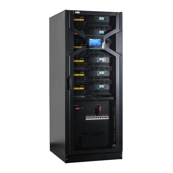
DPA 250 S4 UPS Frame with open door ....... . . - Page 4 D PA 2 5 0 S 4 5 0 - 2 5 0 K W O P E R AT I N G M A N U A L 5.2.2.1 Main Menu ..........41 5.2.2.2 Events log Menu .
- Page 5 9.4.1 UPS Input connections ..........75 9.4.1.1 Mains supply and earth connection .
- Page 7 — S A FE T Y I N S T R U C T I O N S DPA 250 S4 UPS 50-250 kW 380/400/415 V IEC © Copyright 2018 ABB, All rights reserved.
-
Page 8: Important Safety Instructions
1.1 Save these instructions This manual contains important instructions for The UPS system operates with mains, batteries or models DPA 250 S4 that should be followed bypass power carrying high currents and volt- during installation and maintenance of the UPS. - Page 9 1 I M P O R TA N T S A F E T Y I N S T R U C T I O N S THE MANUFACTURER WILL NOT BE HELD a. REMOVE WATCHES, RINGS OR OTHER RESPONSIBLE FOR DAMAGES CAUSED THROUGH METAL OBJECTS.
- Page 11 — U S E R M A N UA L DPA 250 S4 UPS 50-250 kW 380/400/415 V IEC © Copyright 2018 ABB, All rights reserved.
-
Page 12: General Information
IEC/EN 61000-4-6 IEC/EN 61800-4-8 Performance Standard IEC/EN 62040-3 The primary function of the ABB UPS covered by Furthermore, the ABB manufacturer is certified the above standards is to ensure continuity of an successfully in every area according to the model AC power source. -
Page 13: System Nameplate And Identification
2 G E N E R A L I N F O R M AT I O N — 2.2 System nameplate and identification — The UPS system has a nameplate positioned on the inside of the UPS door. It contains 2.2-1: UPS product name and frame type System nameplate... -
Page 14: System Description
3 System description — 3.1 DPA 250 S4 UPS The DPA 250 S4 is a 3 ph transformer less Uninter- • Up to 6 x DPA 250 S4 UPS modules, rated ruptible Power System (UPS). It is a true modular... -
Page 15: Ups Frame With Closed Door
Without display, applicable for: UPS DPA 250 S4 F250-6 BCE SP UPS DPA 250 S4 F250-6 BCE P UPS DPA 250 S4 F250-6 BCE S MBS UPS DPA 250 S4 F250-6 TCE P UPS DPA 250 S4 F250-6 TCE SP... -
Page 16: Dpa 250 S4 Ups Frame With Open Door
D PA 2 5 0 S 4 5 0 - 2 5 0 K W O P E R AT I N G M A N U A L 3.1.3 DPA 250 S4 UPS Frame with open door Bottom cable entry Top cable entry 3.1.4... -
Page 17: Dpa 250 S4 M50 Ups Module
17 17 — 3.2 DPA 250 S4 M50 UPS Module The UPS module of the DPA 250 S4 is the core for monitoring and management. This allows for engine of this modern, high quality UPS. The the modules to be completely independent and module includes all essential parts of a complete act fully redundant with each other. -
Page 18: System Configuration
3.3.2 Parallel system configuration The DPA 250 S4 UPS unit can be paralleled to increase the power capacity up to 1500kW. Up to 6 UPS units with 30 UPS modules can be configured as shown in the table below: Number of UPS units... -
Page 19: Parallel Ups Configuration
3 S Y S T E M D E S C R I P T I O N 3.3.3 Parallel UPS configuration — 3.3.3-1: Ring communication for parallel UPS units The UPS system consisting of parallel UPS units requires: • Master UPS unit equipped with system graphical display, N x UPS modules (N >... -
Page 20: Description Of The Main Elements
D PA 2 5 0 S 4 5 0 - 2 5 0 K W O P E R AT I N G M A N U A L — 3.4 Description of the main elements 3.4.1 Single line diagram with single input feed and common batteries (default) —... -
Page 21: Single Line Diagram With Dual Input Feed And Common Batteries
3 S Y S T E M D E S C R I P T I O N 3.4.2 Single line diagram with dual input feed and common batteries — 3.4.2-1: Single line diagram with dual Applicable for dual input feed and common batteries. The common input feed busbar should be re- input feed and common batteries moved. -
Page 22: Single Line Diagram With Single Input Feed And Separate Batteries
D PA 2 5 0 S 4 5 0 - 2 5 0 K W O P E R AT I N G M A N U A L 3.4.3 Single Line Diagram with single input feed and separate batteries —... -
Page 23: Single Line Diagram With Dual Input Feed And Separate Batteries
3 S Y S T E M D E S C R I P T I O N 3.4.4 Single line diagram with dual input feed and separate batteries — 3.4.4-1: Single line diagram with dual Applicable for dual input feed and separate batteries. The common input feed and battery busbars input feed and separate batteries should be removed. -
Page 24: Functional Description
D PA 2 5 0 S 4 5 0 - 2 5 0 K W O P E R AT I N G M A N U A L 3.4.5 Functional description Section Component Functional Description Main input terminals (X3) X3.1 Rectifier input terminal, phase 1 Provides a connection be-... - Page 25 3 S Y S T E M D E S C R I P T I O N Maintenance bypass switch (Q1) The manual bypass switch connects the load direct to the bypass input supply Maintenance bypass switch (MBS) when it is closed (ON). The UPS is isolated for ser- vices or maintenance work.
-
Page 26: Ups Measure, Control & Monitoring Element Description
Modbus TCP/IP For details refer to chapter "5 Control & Monitoring" The touchscreen graphical display allows the operator DPA 250 S4 HMI (optional) to control and monitor the UPS system. For details refer to chapter "5 Control & Monitoring"... -
Page 27: Operating Modes
4 O P E R AT I N G M O D E S — 4 Operating modes — 4.1 Double conversion mode In double the conversion mode, the load is connected to the UPS Inverter (INV) and the Rectifier is sup- —... -
Page 28: Xtra-Vfi Mode (Enhanced Double Conversion Mode)
D PA 2 5 0 S 4 5 0 - 2 5 0 K W O P E R AT I N G M A N U A L — 4.2 Xtra-VFI Mode (Enhanced double conversion mode) In Xtra-VFI Mode, the UPS system adapts the power capacity according to the partial AC load by put- —... -
Page 29: Battery Mode
4 O P E R AT I N G M O D E S — When the UPS system is in bypass mode, the status of UPS module control panel is displayed as follow : 4.3-2: “Bypass Mode” control panel mimic LED Indicator Color Rectifier... -
Page 30: Maintenance Bypass
D PA 2 5 0 S 4 5 0 - 2 5 0 K W O P E R AT I N G M A N U A L — 4.5 Maintenance bypass The Maintenance Bypass Mode is performed by means of the Q1 MANUAL BYPASS SWITCH. —... -
Page 31: Control & Monitoring
5 C O N T R O L & M O N I TO R I N G — 5 Control & monitoring — 5.1 System display surements (module and system level) and the — 5.1-1: System display ONLY NLY PEOPLE TRAINED BY SERVICE user is able to transfer from double conversion to TECHNICIANS OF THE MANUFACTURER bypass mode and vice-versa. -
Page 32: Rear View
D PA 2 5 0 S 4 5 0 - 2 5 0 K W O P E R AT I N G M A N U A L 5.1.2 Rear View — 5.1.2-1: Rear view PLEASE NOTE THAT THE EMERGENCY SHUTDOWN FUNCTION BY PRESSING THE BUTTONS ON/OFF 1 + ON/OFF 2 IS DISABLED NOTE —... -
Page 33: Home Screen
5 C O N T R O L & M O N I TO R I N G 5.1.4 Home screen — 5.1.4-1: Rear view The display is driven by a menu-prompted software. The home screen is accessible from any screen and gives access to the following: —... -
Page 34: Navigation
D PA 2 5 0 S 4 5 0 - 2 5 0 K W O P E R AT I N G M A N U A L The password for accessing the command Directs the user to the Event log screen where the stored events and Event log menu is different than alarms are shown in chronological order. -
Page 35: Module Selection
5 C O N T R O L & M O N I TO R I N G The color of each block identifies its functional status. There are four main colors in the mimic diagram: • Green: In operation •... - Page 36 D PA 2 5 0 S 4 5 0 - 2 5 0 K W O P E R AT I N G M A N U A L — 5.1.5.2-1: Mimic diagram Example with 5 modules all in operation. Example with 20 modules all in operation.
-
Page 37: Screen Measurements
5 C O N T R O L & M O N I TO R I N G 5.1.5.3 Screen measurements UPS MEASUREMENTS BATTERY XTRA VFI Output Voltage (V) Temperature ( ° Status Output Current (A) Discharge Current (A) Inverters on Output Frequency (Hz) Charge Current (A) Inverters in standby... -
Page 38: X-Tra Vfi
D PA 2 5 0 S 4 5 0 - 2 5 0 K W O P E R AT I N G M A N U A L 5.1.5.7 X-tra VFI By touching the Xtra VFI icon, the user acquires access to the Xtra-VFI settings. The Xtra VFI mode al- lows turning into standby mode of a certain number of UPS modules according to the required power capacity by the AC load. -
Page 39: Control Panel Ups Module
5 C O N T R O L & M O N I TO R I N G — 5.2 Control panel UPS module — The DPA 250 S4 UPS module has a control panel 5.2-1: UPS module ONLY PEOPLE WHICH HAVE BEEN consisting of:... -
Page 40: Control And Navigation Buttons
D PA 2 5 0 S 4 5 0 - 2 5 0 K W O P E R AT I N G M A N U A L 5.2.1.3 Control and navigation buttons The control and navigation buttons allow the user to perform settings and adjustments, monitor the voltages, currents, frequencies, power measurements and scroll the main and sub-menus in the UPS module. -
Page 41: Control Panel Menus
5 C O N T R O L & M O N I TO R I N G 5.2.2 Control panel menus 5.2.2.1 Main Menu 5.2.2.2 Events log Menu 5.2.2.3 Measurements Menu 5.2.2.4 Commands Menu 5.2.2.5 UPS Data Menu... -
Page 42: Set Up User Menu
D PA 2 5 0 S 4 5 0 - 2 5 0 K W O P E R AT I N G M A N U A L 5.2.2.6 Set Up User Menu 5.2.2.7 Setup Service Menu ONLY PEOPLE WHICH HAVE BEEN TRAINED BY SERVICE TECHNICIANS OF THE MANUFACTURER OR HIS CERTIFIED SERVICE PARTNERS ARE ALLOWED TO... -
Page 43: Customer Interface
5 C O N T R O L & M O N I TO R I N G — 5.3 Customer interface — • Each UPS unit is supplied with the customer interface ports which provide information about the 5.3-1: Customer UPS system as follow: interface Slot for optional Modem / Ethernet card... -
Page 44: Input Dry Ports (X3)
Terminal Contact Signal On Display Function X3 / 14 Battery Temperature (Only the optional battery sen- sor from ABB is compatible) X3 / 13 +3.3VDC X3 / 12 GENERATOR_ Generator Operation OPER_ON (N.O.) Min. contact load 12V / 1mA X3 / 11... -
Page 45: Output Dry Port (X2 And X1)
5 C O N T R O L & M O N I TO R I N G 5.3.2 Output dry port (X2 and X1) X2 terminals can hold Cable from 0.2mm2 – 1.5mm2 X2 are potential free contacts and are rated: Max 250Vac/8A; 30Vdc/8A; 220Vdc/0.12A Block Terminal Contact... -
Page 46: Network Management Cards
D PA 2 5 0 S 4 5 0 - 2 5 0 K W O P E R AT I N G M A N U A L 5.3.3 Network management cards — 5.3.3-1: CS141 Basic Support SNMP and The UPS can be equipped with Network inter- Modbus TCP/IP protocols... -
Page 47: Options And Accessories
Carton packaging for one DPA 250 S4 module 4NWP101978R0001 Light sea freight packaging DPA 250 S4 frame 4NWP101978R0001 Sea freight packaging DPA 250 S4 frame Documentation 00-2976 Certificate of origin Legalized invoice is also available. 04-0160 Duplicate of the commissioning report... -
Page 48: Maintenance & Troubleshooting
D PA 2 5 0 S 4 5 0 - 2 5 0 K W O P E R AT I N G M A N U A L — 7 Maintenance & troubleshooting THE OPERATIONS DESCRIBED IN THIS CHAPTER MUST BE PERFORMED BY A CERTIFIED SERVICE ENGINEER OF THE MANUFACTURER OR BY AN AGENT CERTIFIED BY THE MANUFACTURER... -
Page 49: Ups Disposal And Recycling
7 M A I N T E N A N C E & T R O U B L E S H O OT I N G — 7.2 UPS disposal and recycling 7.2.1 For professional users in the European Union 7.2.2 For disposal in countries outside of the European Union... -
Page 50: Fault Identification And Rectification
D PA 2 5 0 S 4 5 0 - 2 5 0 K W O P E R AT I N G M A N U A L 7.3.3 Fault identification and rectification The major alarm conditions that will be encountered are: ALARM CONDITION MEANING SUGGESTED SOLUTION... - Page 53 — I N S TA L L AT I O N M A N UA L DPA 250 S4 UPS 50-250 kW 380/400/415 V IEC © Copyright 2018 ABB, All rights reserved.
-
Page 54: Packing, Transportation & Storage
D PA 2 5 0 S 4 5 0 - 2 5 0 K W O P E R AT I N G M A N U A L — 8 Packing, transportation & storage This chapter contains all the necessary information for the correct packing, transportation and un- packing of the UPS. -
Page 55: Unpacking
8 PA C K I N G , T R A N S P O R TAT I O N & S TO R A G E — 8.2 Unpacking Upon receipt of the goods, make sure that they — VISIBLE TRANSPORT DAMAGES MUST BE 8.2-1: Tiltwatch correspond with the material indicated in the de-... -
Page 56: Standard Package (Film)
D PA 2 5 0 S 4 5 0 - 2 5 0 K W O P E R AT I N G M A N U A L 8.2.1 Standard package (film) — 8.2-1: Standard package unpacking sequence The major alarm conditions that will be encoun- age the cabinet, unwrap the plastic film and re- tered are: move by pulling up the upper part of the bag... -
Page 57: Sea Freight Cases (Wooden Box)
8 PA C K I N G , T R A N S P O R TAT I O N & S TO R A G E 8.2.2 Sea freight cases (wooden box) — 8.2.2-1: Sea freight cases unpacking sequence Perform the following steps to unpack the (Wooden box) UPS equipment from the sea freight package:... - Page 58 D PA 2 5 0 S 4 5 0 - 2 5 0 K W O P E R AT I N G M A N U A L — 5. Remove one of the side walls 6. Remove the last side wall 8.2.2-3: Sea freight cases unpacking se- quence...
-
Page 59: Storage
8 PA C K I N G , T R A N S P O R TAT I O N & S TO R A G E — 8.3 Storage — 8.3.1 8.3.2-1: Batteries If you plan to store the UPS prior to use, keep the UPS unpacked in a dry, clean and cool storage room with an ambient temperature between -25°C and +70°C and humidity of less than 95% non-condensing. -
Page 60: Installation
D PA 2 5 0 S 4 5 0 - 2 5 0 K W O P E R AT I N G M A N U A L — 9 Installation — 9.1 Environmental condition The UPS is designed to be installed indoor, in temperature-controlled rooms. Heating, cooling, forced ventilation and humidification are used to maintain the conditions as shown in the next sub chapters: 9.1.1 Climatic conditions... -
Page 61: Ups Location
9.2-1: DPA 250 S4 service and maintenance shall be respected as indicated below: clearances — 9.2-1 UPS PARALLEL SYSTEM SIDE SINGLE DPA 250 S4 FRAME BY SIDE INSTALLATION OR BATTERY CABINETS IN ROW. Back clearance for ventilation 200 mm 300 mm... -
Page 62: Battery Cabinet Location
D PA 2 5 0 S 4 5 0 - 2 5 0 K W O P E R AT I N G M A N U A L 9.2.1 Battery cabinet location — 9.2.2 Fixing of the UPS to the building 9.2.2-1: Fixing of the UPS to the structure... -
Page 63: Electrical Installation
9 I N S TA L L AT I O N — 9.3 Electrical installation The customer has to supply the wiring to connect the UPS to the local power source. The installa- FOR A CORRECT WIRING CONNECTION, REFER TO THE CHAPTER “9.3.4 UPS tion inspection and initial start-up of the UPS and TERMINAL SIZES”. -
Page 64: Single Input Feed - Terminals Overview
D PA 2 5 0 S 4 5 0 - 2 5 0 K W O P E R AT I N G M A N U A L — 9.3.1 Single input feed - Terminals overview 9.3.1-1: Single input feed - Terminal overview X 2. -
Page 65: Dual Input Feed - Terminals Overview
9 I N S TA L L AT I O N — 9.3.2 Dual input feed - Terminals overview 9.3.2-1: Dual input feed - Terminal overview X 2. 1 X 2. 2 X 2. 3 O U T P U T C O N N E C T IO X2 .1 X2 .2 X2 .3... -
Page 66: Electrical Protection And Cable Sizes
D PA 2 5 0 S 4 5 0 - 2 5 0 K W O P E R AT I N G M A N U A L 9.3.3 Electrical protection and cable sizes Cable sections are recommended according to IEC 60950-1. - Page 67 9 I N S TA L L AT I O N Following external protection and cable sizes are recommended as per UPS power rating UPS POWER RATING Rectifier input fuse [Fuse A] gL or CB C curve, 3P Rectifier input cable 4x35 4x95 4x(2x50)
-
Page 68: Single Input Feed And Separate Battery
D PA 2 5 0 S 4 5 0 - 2 5 0 K W O P E R AT I N G M A N U A L 9.3.3.2 Single input feed and separate battery — 9.3.3.2-1: Single input feed and separate battery block diagram —... - Page 69 9 I N S TA L L AT I O N Following external protection and cable sizes are recommended as per UPS power rating UPS POWER RATING Rectifier input fuse [Fuse A] gL or CB C curve, 3P Rectifier input cable 4x35 4x95 4x(2x50)
-
Page 70: Dual Input Feed And Common Battery
D PA 2 5 0 S 4 5 0 - 2 5 0 K W O P E R AT I N G M A N U A L 9.3.3.3 Dual input feed and common battery — 9.3.3.3-1: Dual input feed and common battery block diagram —... - Page 71 9 I N S TA L L AT I O N Following external protection and cable sizes are recommended as per UPS power rating UPS POWER RATING Rectifier input fuse [Fuse A] gL or CB C curve, 3P Rectifier input cable 4x35 4x95 4x(2x50)
-
Page 72: Dual Input Feed And Separate Battery
D PA 2 5 0 S 4 5 0 - 2 5 0 K W O P E R AT I N G M A N U A L 9.3.3.4 Dual input feed and separate battery — 9.3.3.4-1: Dual input feed and separate battery block diagram —... - Page 73 9 I N S TA L L AT I O N Following external protection and cable sizes are recommended as per UPS power rating UPS POWER RATING Rectifier input fuse [Fuse A] gL or CB C curve, 3P Rectifier input cable 4X35 4x95 4x(2x50)
-
Page 74: Ups Connections
D PA 2 5 0 S 4 5 0 - 2 5 0 K W O P E R AT I N G M A N U A L — 9.4 UPS connections The customer has to supply the cables to connect the UPS to the local power grid source. To ensure cor- rect operation of the UPS and its ancillary equipment it is necessary to provide the mains cables with appropriate fuse protection. -
Page 75: Ups Input Connections
9 I N S TA L L AT I O N 9.4.1 UPS Input connections BEFORE PROCEEDING TO WIRE THE UPS, MAKE SURE THAT YOU HAVE READ AND UNDERSTOOD THE CHAPTER 9.4. NOTE TO ENSURE CORRECT OPERATION OF THE UPS, THE VOLTAGE TOTAL HARMONIC DISTORTION (THDu) OF THE MAINS SHALL NOT EXCEED 75% ACCORDING TO THE LEVELS OF THE STANDARD IEC 61000-2-2. -
Page 76: Output Connections
D PA 2 5 0 S 4 5 0 - 2 5 0 K W O P E R AT I N G M A N U A L MAINS INPUT CABLE UPS TERMINAL BYPASS INPUT CABLE UPS TERMINAL BYPASS Phase L1 X3.1:L1 Phase L1... -
Page 77: Parallel Ups Connections
9 I N S TA L L AT I O N — 9.5 Parallel UPS connections To ensure protection of personnel during the in- 4. The last parallel UPS unit must be connected to — 9.5-1: Communica- stallation of UPS make sure that the connections the first UPS unit (JD1 to JD2) to close the ring tion connection are performed under the following conditions:... -
Page 78: Commissioning
D PA 2 5 0 S 4 5 0 - 2 5 0 K W O P E R AT I N G M A N U A L — 10 Commissioning PLEASE REFER TO CHAPTER "5.2.1.4-LED STATUS INDICATORS" FOR THE MEANING OF THE LED INDICATORS, COLOURS AND BEHAVIOUR NOTE HE OPERATIONS DESCRIBED IN THIS CHAPTER MUST BE PERFORMED BY A SERVICE ENGINEER FROM THE... -
Page 79: Q1 And Q2 Feed-Back Check
1 0 C O M M I S S I O N I N G LED indicators status on all modules Display on all modules LED INDICATION COLOR DUAL INPUT FEED CONFIGURATION Rectifier Green Bypass Load Battery Flashing Red The 3 LEDs (Orange, Red and Green) present In particular verify: on all Parallel Interface boards (one in each •... -
Page 80: Modules Check
D PA 2 5 0 S 4 5 0 - 2 5 0 K W O P E R AT I N G M A N U A L Q2 ON (Closed) Q2 OFF (Opened) Display in case of single input feed configuration. 10.1.5 Modules check Load-On to INVERTER mode the last module... - Page 81 1 0 C O M M I S S I O N I N G Load-ON to INVERTER mode the last module in the parallel installation (The module in the uppermost slot of the last frame). LED indicators status: Module display: LED INDICATION COLOR SINGLE INPUT FEED CONFIGURATION...
-
Page 82: Battery Connection And Check
D PA 2 5 0 S 4 5 0 - 2 5 0 K W O P E R AT I N G M A N U A L Only one Master module must be present in 23. At the end of the start-up procedure (all mod- the complete parallel system when all output ules loaded in INVERTER mode and all out-put isolators Q2 are in the ON position (closed)! -
Page 83: Connecting The Load
1 0 C O M M I S S I O N I N G Turn the general mains Rectifier Line isolator to the ON position (closed) and verify that all modules in the parallel system switch back to normal operation (INVERTER mode) 10.1.8 Connecting the load Now transfer the load from INVERTER to... -
Page 84: Shut-Down Procedure
D PA 2 5 0 S 4 5 0 - 2 5 0 K W O P E R AT I N G M A N U A L — 11 Shut-down procedure PLEASE REFER TO CHAPTER "5.2.1.4-LED STATUS INDICATORS" FFOR THE MEANING OF THE LED INDICATORS, COLOURS AND BEHAVIOUR NOTE HE OPERATIONS DESCRIBED IN THIS CHAPTER MUST BE PERFORMED BY A SERVICE ENGINEER OF THE... - Page 85 1 1 S H U T- D O W N P R O C E D U R E If present, turn to the OFF position (open) the parallel system “Main External Output Isolator” or open the external output fuses. Turn to the OFF position (open) the battery breakers present on all frames and external battery cabinets or racks breakers or fuses.
-
Page 86: Maintenance Bypass Operations
Load transfer from inverter mode to maintenance bypass Situation of UPS parallel system before starting the procedure: The load is protected by DPA 250 S4 UPS running in normal operation. All Modules operating on INVERTER mode! LED indicators status on all modules... - Page 87 1 2 M A I N T E N A N C E B Y PA S S O P E R AT I O N S LED indicators status on all modules Display on all modules LED INDICATION COLOR SINGLE/DUAL INPUT FEED CONFIGURATION Rectifier Green...
-
Page 88: Load Transfer From Maintenance Bypass To Inverter Mode
D PA 2 5 0 S 4 5 0 - 2 5 0 K W O P E R AT I N G M A N U A L — 12.2 Load transfer from maintenance bypass to inverter mode Situation of UPS parallel system before starting the procedure: The load is supplied directly by Input Mains power (Via maintenance bypass switches Q1 if present... - Page 89 1 2 M A I N T E N A N C E B Y PA S S O P E R AT I O N S If present, turn to the OFF position (open) the display or the general TFT display installed maintenance bypass switch Q1 on all frames on the frame.
-
Page 90: Adding/Replacing A Ups Module
D PA 2 5 0 S 4 5 0 - 2 5 0 K W O P E R AT I N G M A N U A L — 13 Adding/replacing a UPS module PLEASE REFER TO CHAPTER "5.2.1.4-LED STATUS INDICATORS" FOR THE MEANING OF THE LED INDICATORS, COLOURS AND BEHAVIOUR NOTE THE OPERATIONS DESCRIBED IN THIS CHAPTER MUST BE PERFORMED BY A SERVICE ENGINEER OF THE... - Page 91 1 3 A D D I N G/ R E P L A C I N G A U P S M O D U L E Load OFF the module by means of the ON/ ternal battery cabinets or racks breakers or OFF button present on its control panels (Al- fuses.
-
Page 92: Insert The Module In The Frame
D PA 2 5 0 S 4 5 0 - 2 5 0 K W O P E R AT I N G M A N U A L 13.1.2 Insert the module in the frame The module must be previously set according to Push UPS module to its final position and system personalization. - Page 93 1 3 A D D I N G/ R E P L A C I N G A U P S M O D U L E LED indicators status on the module Display on the module LED INDICATION COLOR SINGLE/DUAL INPUT FEED CONFIGURATION Rectifier Green...
-
Page 94: Redundant Multi-Module System
D PA 2 5 0 S 4 5 0 - 2 5 0 K W O P E R AT I N G M A N U A L — 13.2 Redundant multi-module system If in a redundant parallel system an UPS module is load to bypass! faulty, the load will continue to be protected by The same situation exist in the case of module... -
Page 95: Insert The Module In The Frame
1 3 A D D I N G/ R E P L A C I N G A U P S M O D U L E INVERTER MODE LED indicators status on all operating modules Display on all operating modules LED INDICATION COLOR SINGLE/DUAL INPUT FEED CONFIGURATION... - Page 96 BYPASS MODE (ECO MODE) LED indicators status on all operating modules Display on all operating modules LED INDICATION COLOR SINGLE/DUAL INPUT FEED CONFIGURATION Rectifier Green Bypass Green Load Yellow Battery Green The load is now protected by the DPA 250 S4 UPS.
-
Page 97: Capacity Multi-Module System
1 3 A D D I N G/ R E P L A C I N G A U P S M O D U L E — 13.3 Capacity multi-module system If in the capacity parallel system a UPS module ex- The same situation exists when a module requires periences a fault and there is not enough capacity maintenance and the remaining ones still operat-... -
Page 98: Insert The Module In The Frame
D PA 2 5 0 S 4 5 0 - 2 5 0 K W O P E R AT I N G M A N U A L Load OFF the module by means of the ON/ Turn to OFF position (open) the battery OFF button present on its control panels (Al- breakers of the slot where the faulty module/ ways confirm with “ENTER”... - Page 99 1 3 A D D I N G/ R E P L A C I N G A U P S M O D U L E LED indicators status on the module Display on the module LED INDICATION COLOR SINGLE/DUAL INPUT FEED CONFIGURATION Rectifier Green...
- Page 100 D PA 2 5 0 S 4 5 0 - 2 5 0 K W O P E R AT I N G M A N U A L 11. Turn to OFF position (open) the maintenance in the event log of the modules as soon as all bypass switch Q1 (if present) and turn to OFF maintenance bypass switches Q1 are turned position the external output bypass switch if...
-
Page 101: Operation Procedures
1 4 O P E R AT I O N P R O C E D U R E S — 14 Operation procedures — 14.1 Remote shutdown The REMOTE SHUTDOWN must use a normally closed contact, which opens to operate the remote shut —... -
Page 102: Generator On Facility
D PA 2 5 0 S 4 5 0 - 2 5 0 K W O P E R AT I N G M A N U A L — 14.2 Generator ON facility — The Generator ON facility must use a normally open contact that closes to indicate that a generator is 14.2-1: Generator ON running and supplying input power to UPS. -
Page 103: Xtra Vfi
1 4 O P E R AT I O N P R O C E D U R E S — 14.3 Xtra VFI 14.3.1 Setup mode Redundancy level In order to set up the Xtra VFI feature correctly, The redundancy level parameter has to be in- these two parameters must be known: serted by the user (service menu ›... -
Page 104: Display Menu
D PA 2 5 0 S 4 5 0 - 2 5 0 K W O P E R AT I N G M A N U A L 14.3.2 Display menu — 14.3.2-1: Naviga- tion overview Navigation overview The picture below shows all the views (screens) The picture below also illustrates which button relevant for the Xtra VFI Feature (the display has a (icons) takes the user to a specific screen. - Page 105 1 4 O P E R AT I O N P R O C E D U R E S Xtra VFI measures screen — 14.3.2-2: Xtra VFI measures screen Figure 14.3.2-2 below, shows the Xtra VFI the Home screen by pressing the icon and then measurement screen which is accessible via —...
- Page 106 D PA 2 5 0 S 4 5 0 - 2 5 0 K W O P E R AT I N G M A N U A L Xtra VFI status bar screen — 14.3.2-3: Xtra VFI status bar screen Figure 14.3.2-3 below, shows the Xtra VFI status surements screen by pressing the icon or via...
-
Page 107: Options
• Manual Bypass CERTIFIED BY THE MANUFACTURER Please indicate these option features when plac- ABB modular system is provided with several fea- ing an order. tures that allow for easy adaptation to the re- quired sites conditions. Following the “field in- stallable kits”:... -
Page 108: Cs121 Basic
D PA 2 5 0 S 4 5 0 - 2 5 0 K W O P E R AT I N G M A N U A L The small (125x70 mm) External SNMP adapter — 15.1-3: CS141 comes with following interfaces: advanced box 1. -
Page 109: Cs121 Advanced
1 5 O P T I O N S 15.1.2 CS121 advanced — 15.1.2-1: CS141 advanced For interfacing UPS with the network and allowing users to connect additional sensors and I / O options either directly to the card or with sensor manager. Available in slot and box formats. Supports the following protocols HTTP, ModBus TCP ,SNMP Telnet FPT, SMTP (e-mail), ModBus RS-485 —... -
Page 110: Installation Of The Snmp Board
D PA 2 5 0 S 4 5 0 - 2 5 0 K W O P E R AT I N G M A N U A L — 15.1.4 Installation of the SNMP board 15.1.4-1: SNMP board 2. Insert the SNMP card inside the slot installation (1) 1. -
Page 111: Battery Temperature Sensor
— 15.3.2-1 ONLY THE OPTIONAL BATTERY SENSOR THE BATTERY TEMPERATURE PROBE IS A FROM ABB IS COMPATIBLE CLASS 2 DEVICE (SELV CIRCUITS). PLEASE ROUTE THE CABLE TO MAINTAIN A THE ADHESIVE OF THE BATTERY SENSOR MINIMUM OF 6MM FROM PRIMARY... -
Page 112: Attachments
D PA 2 5 0 S 4 5 0 - 2 5 0 K W O P E R AT I N G M A N U A L — Attachments — Technical data sheet... - Page 114 — www.abb.com/ups ups.sales@ch.abb.com © Copyright 2018 ABB. All rights reserved. Specifications subject to change without notice.