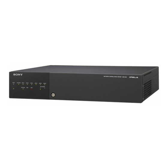
Sony IPELA NSR-500 Series User Manual
Hdmi network surveillance server
Hide thumbs
Also See for IPELA NSR-500 Series:
- Installation manual (276 pages) ,
- Setup procedure (17 pages) ,
- Brochure & specs (4 pages)

Related Manuals for Sony IPELA NSR-500 Series


Summary of Contents for Sony IPELA NSR-500 Series
- Page 1 4-272-495-16 (1) Network Surveillance Server User’s Guide Software Version 1.6 and Later Before operating the unit, please read this manual thoroughly and retain it for future reference. NSR-500 Series © 2011 Sony Corporation...
-
Page 2: Table Of Contents
Table of Contents Chapter 1 Introduction Overview...................6 Features and Functions ..............8 Front (When the Front Cover and the HDD Cover are Opened) ..8 Rear ....................... 9 System Requirements ..............11 Chapter 2 Administration Menu Overview..................12 Displaying the Administration Menu ........... 12 Changing Initial Settings with the Setup Menu...... - Page 3 Chapter 4 Application Settings Alarms and Events ................ 33 Displaying Configuration Window ..........33 Registering Devices ..............34 Changing Registration Details............. 34 Deleting Devices ................. 35 Settings Required when Using SNC-CS20/CM120/DS10/DM110/ DS60/DM160................35 Registering Device Groups ..............36 Details of Each Screen ................ 37 Configuring Camera Video Settings ..........
- Page 4 Changing Settings of Alarm Output Pins of Camera ......79 Changing Settings of Alarm Output Pins of Barionet ......80 Setting Items of the [Alarm Out] Tab ..........80 Configuring Action Settings ............82 Manual Action ..................82 Event/Alarm Actions ................85 Configuring Mail Notification Settings ........
- Page 5 Index ....................132 Trademarks • “IPELA” and are trademarks of Sony Corporation. • The terms HDMI and HDMI High-Definition Multimedia Interface, and the HDMI Logo are trademarks or registered trademarks of HDMI Licensing LLC in the United States and other countries.
-
Page 6: Chapter 1 Introduction
Introduction Chapter Overview The NSR-500 series is a network surveillance server for network cameras. The NSR series allows you to monitor and record JPEG, MPEG-4, and H.264 images from network cameras via the network. It also allows you to search and play back recorded images, making the NSR a truly versatile monitoring system. - Page 7 With a purpose-built rack mounting kit, the unit can be installed in a standard universal pitch EIA 19-inch rack. For details on the rack mounting kit, contact your Sony dealer. High reliability The NSR supports redundant configurations such as RAID and performs with high reliability.
-
Page 8: Features And Functions
During operation, this LED is lit green when the E Fan unit system is functioning normally. When a system error For details on maintenance, contact your Sony dealer. or other problem occurs, it lights red. If this LED is lit red, contact your Sony dealer. Features and Functions... -
Page 9: Rear
M Power switch Caution Press this to turn on the unit. Pressing and holding down the power switch If you press the power switch during operation, the (approximately 5 seconds) turns off the unit forcefully. POWER LED blinks green for up to 3 seconds. Pressing the power switch again during this time turns N POWER LED off the unit. - Page 10 HDMI input. • For details on using iSCSI storage, contact your Monitor connector 2 and the HDMI monitor connector Sony dealer. cannot be used at the same time. This connector can only be used when an NSBK- CAUTION DH05 (optional) is mounted.
-
Page 11: System Requirements
- XGA (1,024 × 768) However, WUXGA is not supported on HDMI-compatible devices. 2) Contact your dealer for details about compatible Sony network cameras. 3) The NSR requires an NSBK-EB05 (optional) expansion. 4) Use a USB keyboard with a cable. However, keys other than the standard may not function. -
Page 12: Chapter 2 Administration Menu
Administration Menu Chapter Overview Displaying the Administration Menu The Administration Menu allows you to change settings that were configured with the Setup Wizard when you Enter the user name and password in the logon screen, turned on the NSR for the first time, and also allows you to and click [Administration Menu]. -
Page 13: Changing Initial Settings With The Setup Menu
Details on Setting Items Changing Initial Settings with the Setup Menu Setting Items of Language Screen Select the language to display on the screens, and click [OK]. Use the Setup Menu to change settings that were configured with the Setup Wizard when you turned on the NSR for the first time. - Page 14 Date Time Format LAN2: Network cameras (LAN2 can only be used when Select the format for the date and time. using a different segment from LAN1.) 1) Connect remote clients to the network specified with the [Network Enable NTP Server Interface for Remote Client] setting (either LAN1 or LAN2) in the Server Select the check box to enable the NTP server of NSR.
- Page 15 For details, contact the administrator of the network Setting Items of Disk Screen to which you will connect. Configure iSCSI settings. 2 Click [OK]. Caution Contact your Sony dealer when using iSCSI. Changing Initial Settings with the Setup Menu...
- Page 16 Select the severity level for SNMP trap transmission. An SNMP trap will be sent when severity levels meet or exceed this setting. For details on SNMP traps, contact your Sony dealer. Notes • If you do not set a server name, a default name (e.g., NSR500_DB12) to which the last four digits of this unit’s LAN1 MAC address is appended is set.
- Page 17 Setting Items of UPS Screen Setting Items of Serial Port (Analog Camera) Screen Configure settings related to UPS, and click [OK]. Configure settings related to the analog camera connection. Configure each item, and click [OK]. (This screen only appears when an optional NSBK-EB05 is installed.) Enable Select this when using a UPS.
-
Page 18: Configuring Settings Related To Servers
Setting Items of Camera Auto Registration Configuring Settings Screen When you want to enable the camera auto registration Related to Servers function, select the [Display confirmation dialog box for automatic camera registration at startup] check box and click [OK]. If you select this check box, the Camera Configure these settings when, for example, you want to Automatic Registration screen appears when the unit starts change the network settings to match the network... - Page 19 You can set one master server for uniformly managing • When the central server mode or the server port is users in the system, and multiple slave servers. changed, a message appears and the system restarts. • If you changed the network interface for the remote 1) This is for when you want to perform common user client, you must restart the system.
-
Page 20: Installing Patch Files
2) Changing the password does not guarantee prevention of log on by unauthorized users. 3) Sony Corporation is not liable for any loss of profits incurred by the customer as a result of such occurrences. The customer is responsible for configuring appropriate settings and A list of patch file names appears. -
Page 21: Saving And Restoring Configuration Data
Confirm the content of the message, and click [Yes]. Saving and Restoring Caution Configuration Data The NSR will automatically restart after installation of certain patch files. A confirmation screen will appear if restart is necessary. If you cannot stop your current You can save the configuration data of NSR to external operations, select [No] to cancel installation, and media, and restore saved configuration data. -
Page 22: Restoring Configuration Data
Select the media to save the configuration data, enter Restoring Configuration Data the file name for the configuration data, and click [OK]. Caution You can use alphanumeric characters and some • Note that the following information is not restored. symbols (periods (.), hyphens (-), underscores (_)) –... -
Page 23: Exporting System Information
Click [OK]. Exporting System A confirmation message appears. Information Click [Yes]. A progress bar appears during restoring, NSR restarts You can save NSR system information as files onto when the process is finished, and the configuration external media. data is restored. Note System information consists of NSR system configuration information and logs. -
Page 24: Installing Licenses
You can register up to 16 cameras normally, but this can be increased to up to 24 cameras. Notes • For details on licenses, refer to the NSBK-CL05 Installation Guide (PDF). • For details on acquiring licenses, contact your Sony dealer. Installing Licenses... -
Page 25: Chapter 3 Basic Operation
Basic Operation Chapter Overview Logging On to the NSR This chapter describes how to perform the following basic Before you can use the NSR, you must first log on. operations on the NSR, including logging on, using various windows, changing the password, and turning off Press the power switch on the front of the NSR to turn the unit. - Page 26 Enter the user name and password, and click [Logon]. • If you log on with the [Auto-Logon] check box selected, the logon screen will not appear the next time you start the application, and you will be logged on automatically. •...
-
Page 27: Basic Window Operations
Basic Window Operations This section provides a brief description of the basic operations for each screen. The unit includes a Main screen for monitoring images, a configuration screen for configuring various settings, and an Administration Menu for performing configurations and operations related to the NSR unit. Logon Screen Recorder Settings Screen Administration Menu... -
Page 28: Main Screen
Administration Menu When you click [Administration Menu] after entering your user name and password in the logon screen, the Administration Menu screen appears. Click each button to configure settings and perform operations related to the NSR unit. For details on settings that can be configured from the Administration Menu, see Chapter 2 “Administration Menu” (page 12). - Page 29 Configuration screen Configure settings that are necessary for operating the NSR, such as camera registration, schedule settings, and user registration. Click the button for the item you want to configure. Returns to the Main screen. Setting items appear based on the button you clicked. For details on setting items and how to configure them, see Chapter 4 “Application Settings”...
-
Page 30: Changing The Password
Note Changing the Password If [Enable Auto Logon] is enabled, the logon screen will not appear during application startup, and you will be logged on automatically. To change the password You change the password for logging on to NSR. while [Enable Auto Logon] is enabled, first log off from the Main screen. -
Page 31: Logging Off
Logging Off Locking the NSR Click in the Main screen. You can temporarily lock the screen in its current state. Use the lock function when you need to leave your seat during operation, for example. Click in the Main screen. The following screen appears. -
Page 32: Shutting Down And Restarting The Nsr
Shutting Down and Viewing Version Restarting the NSR Information Always shut down or restart the NSR from the Main Click [Information] in the logon screen. screen. Click at the top of the Main screen, and select [Shutdown] or [Reboot] from the menu that appears. The following screen appears. -
Page 33: Chapter 4 Application Settings
Application Settings Chapter Alarms and Events Displaying Configuration Window You can configure sensor inputs, VMD, manual actions, and other triggers as alarms or events on the NSR, and You can configure various settings in the Configuration record or execute actions in response. Although alarms and window. -
Page 34: Registering Devices
For details on the operation, refer to the Installation Manual (separate document). Notes • When using non-Sony IP cameras (network cameras) or ONVIF (Open Network Video Interface Forum) cameras, simultaneous registration through basic configuration and automatic detection is not possible. -
Page 35: Deleting Devices
• If a common value cannot be set for multiple cameras, Click (Delete). that setting item is unavailable. Change the combination of cameras to select, and then configure the setting. Select the camera(s) you want to change the registration details of on the Device Configuration screen. -
Page 36: Registering Device Groups
functions and then perform the setup. When you select the Select the function combination one line at a time in combination of functions, the setting range for each item is order from the top left, and click the [OK] button. determined automatically. -
Page 37: Details Of Each Screen
Deleting a Group Select the group you want to delete in the tree, and click (Delete) to delete the group. Notes • When you want to create a sub-group below a group, select the upper group and click (Add). • When you want to rename a group, click a group name selected in the tree and then enter the new group name. - Page 38 (Add) Global ID This displays the Add Device dialog box (page 40) for Enter a number for the global ID. registering a device manually. In NSR and RealShot Manager Advanced, cameras are managed by assigning IDs to the connected cameras (Delete) individually.
- Page 39 Setting Items of Multiple Camera Device List This displays a list of the devices detected with the Registration Dialog Box automatic search. This dialog box displays the results of the automatic search, and allows you to register the detected devices Terget simultaneously.
- Page 40 Setting Items of Input All Dialog Box Setting Items of Add Device Dialog Box This dialog box allows you to simultaneously configure Enter the setting items when registering a device manually. the same setting values to multiple selected devices for the This dialog box is displayed by clicking (Add) on the following setting items when registering devices detected...
-
Page 41: Configuring Camera Video Settings
User Name Configuring Camera Enter the user name for connecting to the device. It can be up to 32 characters and consist of alphanumeric characters. Video Settings Password Enter the password for connecting to the device. It can be up to 32 characters and ASCII characters (upper or lower You can configure settings related to the images captured case alphanumeric characters and symbols (! "... - Page 42 Setting Items of [Video] Tab Bit Rate (for MPEG4 or H.264) Select the bit rate for images of the camera. This tab allows you to change settings related to images captured from the camera selected in the tree on the left. Frame Rate After configuring each item, click [Apply] to save your Select the frame rate for images of the camera.
- Page 43 View-DR Edge Storage Select whether the View-DR function is turned on or off Select this check box if the camera is equipped with an for cameras equipped with this function. Edge Storage function and you want to download the Turning on the View-DR function allows the camera to images stored on the camera’s Edge Storage.
- Page 44 Wide dynamic range (View-DR) Notes Select whether the View-DR function is turned on or off • The setting items and selectable values differ depending for cameras equipped with this function. on the camera. In addition, some functions may be Turning on the View-DR function allows the camera to limited depending on configurations.
-
Page 45: Configuring Camera Operations
Configure each item. Configuring Camera Operations In NSR, you can configure the following settings for camera operations. • “Configuring Preset Positions” (page 45) You can configure preset positions for the camera. • “Configuring Camera Tours” (page 46) You can configure camera tours for sequentially moving a camera to the pan, tilt, and zoom positions specified for presets. -
Page 46: Configuring Camera Tours
Deleting Presets Configure each item. Select the camera for which you want to delete the preset position, and click the [Preset] tab. Select the preset to delete in the list at the top of the screen, and click [Clear]. The preset is deleted. Click [Set Preset]. -
Page 47: Configuring Shadow Tours
8 Click [Test] to show and check the set tour. To Configure a New Tour Camera Tour Operation Click [Device] at the top of the Configuration screen. In NSR, the camera tour function is achieved by configuring the same stay duration and speed for each position specified by a camera preset. -
Page 48: Configuring Masks (Camera)
The mask function works in conjunction with the camera’s pan, tilt, and zoom movements to constantly hide the specified areas. The mask function (camera) can only be used with Sony SNC-XX600 series (XX represents two letters) network cameras that support camera masks. - Page 49 Setting Items of [Mask (Camera)] Tab D Pan, Tilt, and Zoom Toolbar This is available when the camera is equipped with pan, After configuring each item, click [Apply]. tilt, and zoom functions. Use the buttons to control the pan, tilt, and zoom of the camera, and check whether or not the camera moves correctly to hide a configured area.
-
Page 50: Configuring Control Protocols For Analog Cameras
Configuring Control Protocols for Note Analog Cameras Make sure that the serial port is configured according to the analog camera you are using. You can configure the serial port from the Setup Menu of the Administration When an optional NSBK-EB05 is installed, configure the Menu. -
Page 51: Configuring Audio
Configuring Audio Settings Related to Configure settings for monitoring audio. Monitoring Click [Device] at the top of the Configuration window. You can configure the following settings related to the monitor layout and camera images. • “Configuring Monitor Layout Settings” (page 51) You can create multiple layouts according to your operating environment and objective. - Page 52 Note “Custom Layout A” and “Custom Layout B” are preset layout groups. Use them according to your objective. The area on the left side changes to the display for setting the layout. Configure each item. For details on each of the items, refer to “Setting Items of Insert Background Image Dialog Box”...
- Page 53 Select the layout you want to delete from the [Layout] Note tree on the Layout Configuration screen, and click Default layouts cannot be deleted. (Delete). A confirmation message appears. B Name Enter the name of the layout. It can be up to 32 characters Click [Yes].
- Page 54 (Send Backward) Setting Items of Properties Use this button to move the selected image backward. x When a monitor frame is selected: (Send to Back) Use this button to move the selected image behind all • [General] Tab others. Select the camera to assign to the monitor frame. (Flip Horizontally) Use this button to flip the selected image horizontally.
- Page 55 Scale to Monitor Frame Click Action Images are enlarged or reduced to fit the monitor Select the check box to enable an action, and select the frame. action to perform. Keep Aspect Ratio • [Camera Select] Tab This maintains the image aspect ratio, regardless of Set the function for displaying an image of the the size of the monitor frame.
- Page 56 Alarm/Event Trigger Off Setting Items of Insert Background Image Highlight display ends when the alarm or event Dialog Box trigger ends. This dialog box imports an image such as a map or floor plan for the background. Icon Click It is displayed by clicking [Background] on the Layout Highlight display ends when you click the image.
-
Page 57: Assigning Cameras To Monitor Frames
Assigning Cameras to Monitor Frames Assign a camera for displaying images to each monitor frame. Select a layout from the [Layout] tree on the Layout Configuration screen. Assign the cameras to monitor frames. The following methods are available for assigning Location cameras. - Page 58 A layout tour is added to the tree. 2 Enter a name for the tour. 3 When you want to change the display order, select a layout in the list and click (Move layout of tour up one place) or (Move layout of tour down one place).
-
Page 59: Configuring Motion Detection Settings
Configure each item on the [VMD] tab, and configure Configuring Motion the motion detection area. Detection Settings You can configure the motion detection and object detection functions for cameras on the NSR. About Motion Detection and Object Detection What is Motion Detection? A function for detecting moving objects (such as people or cars). - Page 60 C Preview This displays the images from the camera. Use the following procedure to create an area for detecting motion. • Click and drag the mouse over the image to create a motion detection area (red frame). By dragging each edge of the area, you can change the size of the area.
-
Page 61: Configuring Camera Tamper Detection And Audio Detection
Caution Configuring Camera After an unattended object is detected (after the alarm Tamper Detection and occurs), another unattended object may not be detected for up to one minute. Audio Detection Area 1 to Area 4 Select Active or Inactive for each detection area. For the SNC-XX600 series (XX represents two Cameras equipped with the tamper detection function can letters), select whether each area is enabled or... -
Page 62: Configuring Edge Storage Settings
2 To configure the sound pressure detection function Configuring Edge on the camera, select the [Audio detection] check box. Storage Settings 3 Click [Apply]. The camera tamper detection function is configured. If the camera is equipped with an Edge Storage function, and you can configure settings for downloading the images stored on the camera’s Edge Storage. -
Page 63: Configuring Settings Related To Storage
Select the location to add as storage, and click [OK]. Configuring Settings Related to Storage You can configure settings for storage in the storage location for image data and audio data of cameras. You can configure up to 32 storage items, and configure settings such as the maximum size of the recording file for each storage item. - Page 64 Configuring Storage for Each Recording Configure each item, and click [Apply]. Type ([Record Type] Mode) You can specify storage for each recording type, such as manual recording, schedule recording, and alarm recording. Select the server for which you want to configure storage from the [Server] tree, and click the [Storage Assign] tab.
- Page 65 A Storage List I Close This displays a list of the storage configured for the server This closes the screen. selected in the [Server] tree. Setting Items of [Storage Assign] Tab Name This displays the name of the storage. This tab is displayed by clicking [Server] in the [Configuration] window, and clicking the [Storage Capacity (%) Assign] tab.
-
Page 66: Configuring Settings Related To Deleting Recording Data
Manual Record Manual Record Select storage for saving for manual recording. Select storage for saving for manual recording. Schedule Record Schedule Record Select storage for saving for schedule recording. Select storage for saving for schedule recording. Alarm Record Alarm Record Select storage for saving for alarm recording. - Page 67 • When the data overwrite function is enabled and a file Configure each item on the [Data Cleanup] tab, and currently being played back falls under the conditions click [Apply]. for deletion, playback of that file stops and the file is deleted.
- Page 68 Setting Items of the [Data Cleanup] Tab Edge Storage (days) Enter the number of storage days for Edge Storage This tab is displayed by clicking [Server] in the recording. [Configuration] window, and clicking the [Data Cleanup] tab. E Apply After configuring each item, click [Apply]. This saves the settings.
-
Page 69: Configuring Recording Schedules
segmented, it will be displayed as a different record in Configuring Recording searches and the like. 1) The number 10,000 is the total number of files since Schedules recording started. It includes files that are deleted with the cleanup and data overwrite functions. The time period segmented will differ depending on the You can configure a recording schedule for each camera to frame rate and resolution. - Page 70 Click [Recurrent] to switch to recurrent view, and For details on how to view the schedule, refer to “Setting click [New Record]. Items of Schedule Screen” (page 73). Configuring a Schedule for a Specific Date and Time You can configure a schedule for a specific date and time to specify a date and time to run a schedule.
-
Page 71: Configuring Alarm Recording And Event Recording
For details on each of the items, refer to “Setting Items Click [Recurrent] or [Date Time] to switch to the view of New Record Dialog Box” (page 74). of the schedule you want to configure, and click [New Record]. 1 Enter a name for the schedule. 2 Select the type of schedule. - Page 72 For details, refer to “About Relationship Between About Relationship Between Sensor and Sensor and Camera when Alarm Occurs” (page 72). Camera when Alarm Occurs When [Record by each event]: 6 When [Record by each event] is selected, configure the input pin of the camera or I/O device that will The input pin of the selected camera itself triggers the be the trigger for alarm recording or event beginning of recording.
- Page 73 Setting Items of Schedule Screen This screen is displayed by clicking [Schedule] in the Configuration window. Screen example: When recurrent schedule (recurrent view) • Guide lines are shown in 15-minute intervals, and by dragging the edges of each scheduled time slot, you can change the start and end times of the action.
- Page 74 Setting Items of New Record Dialog Box E Record Duration This item is displayed in the case of alarm recording or This dialog box is displayed by clicking [New Record] on event recording. the Schedule screen (page 74). Set the record duration for when an event occurs. The items that are displayed differ depending on the type of recording.
- Page 75 F Associate recording data with alarm H Record Camera This item is displayed for schedule recording. Add the camera to become the target for recording to the Select the check box to associate the recording data with list, and configure settings related to images captured from the alarm.
-
Page 76: Configuring Sensor Inputs
Configure each item on the [Physical Sensor In] tab, Configuring Sensor and click [Apply]. Inputs You can configure settings related to the sensor inputs incorporated in NSR and cameras, and Barionet (Barix I/O box) sensor inputs. Sensor inputs can be specified and used for actions and schedule recording events. -
Page 77: Changing Settings Of Sensor Input Pins Of Barionet
For details on each of the items, refer to “Setting Items Adding Logical Sensor Input Pins to of the [Logical Sensor In] Tab” (page 78). The sensor input settings are changed. The adding of a logical sensor input pin to NSR allows for linking with the external device via the network. -
Page 78: Deleting Logical Sensor Input Pins Created For Nsr
3 Click [Apply]. Sensor Input Pin List This displays a list of the sensor input pins configured for The logical sensor input pin is added. the device selected in the tree structure. Enable Select the check boxes to enable the pins for the sensor Deleting Logical Sensor Input Pins inputs. -
Page 79: Configuring Alarm Output Settings
Configure each item on the [Physical Alarm Out] tab, Configuring Alarm Output and click [Apply]. Settings You can configure settings related to the alarm outputs incorporated in NSR and cameras, and Barionet (Barix I/O box) alarm outputs. Outputs are used to transmit alarms to devices equipped with alarm input functions, such as warning lamps and door opening devices. -
Page 80: Changing Settings Of Alarm Output Pins Of Barionet
Configure each item on the [Alarm Out] tab, and click Configure each item on the [Alarm Out] tab, and click [Apply]. [Apply]. For details on each of the items, refer to “[Alarm Out] For details on each of the items, refer to “[Alarm Out] Tab (I/O Device)”... - Page 81 Name Caution Enter the names of the alarm outputs. They can be up To use alarm outputs, the alarm output pin settings on to 32 characters long. the device must also be enabled. Pulse Name Select the check box when you want to specify and Enter the names of the alarm outputs.
-
Page 82: Configuring Action Settings
Click (Add). Configuring Action Settings In NSR, you can configure the action for when, for example, a sensor input, VMD (camera) or system alarm is Configure the following items, and register the action. detected, or for when a manual action is performed. Relationship Between Events and Actions When an event such as an The action corresponding... - Page 83 Performing a Manual Action Setting Items of Manual Action Screen You can perform an action from the Manual Action toolbar You can configure manual action settings. in the main window. The items that are displayed differ depending on the device for performing the action.
- Page 84 Camera Control [System Action] Tab Select the check box to perform an action for controlling the camera, and specify the control method. Preset This moves the camera to the specified preset position. Tour This performs the specified camera tour. Action End Preset Specify the preset position for when the action ends.
-
Page 85: Event/Alarm Actions
Beep Click [Schedule] at the top of the Configuration Select the check box to play a beep tone. window. If you select this, select a beep tone type. This item is only displayed for a server. The beep sound is output for a predetermined duration from the device connected to the audio connector specified in the Audio screen of the Setup Wizard or the Setup Menu. - Page 86 7 Click [OK]. The range that can be specified is 00:00:00 to 23:59:59 The event/alarm action is created. (hours/minutes/seconds). Click [Apply]. The event/alarm action is saved. When event/alarm action for a specific date and time: For details on how to view the schedule, refer to “Setting Configure the start date and time and end date and time Items of Schedule Screen”...
- Page 87 System Alert Pin List Select the check box to use a system alert as the Select the check boxes for the output pins to be target trigger. for performing an action to change the pin state. [I/O Device Action] Tab H Action Configure the action to perform.
- Page 88 Send e-mail I OK Select the check box to send a notification by mail to a This creates an event/alarm action in accordance with the specified mail address. set values, and closes the dialog box. E-mail Address J Cancel Enter an e-mail address. This cancels your settings, and closes the dialog box.
-
Page 89: Configuring Mail Notification Settings
5 Enter the mail address for sending test mail. Configuring Mail 6 After you enter each address, click [Send Test Mail] Notification Settings and confirm that mail can be sent correctly. 7 Click [Apply]. When an event occurs, a notification can be sent by e-mail to a pre-registered mail address. -
Page 90: Configuring System Alert Settings
For details on actions, refer to “Configuring Action Configuring System Alert Settings” (page 82). Settings Setting Items of the [System Alert] Tab This tab is displayed by clicking [Server] in the [Configuration] window, and clicking the [System Alert] A system alert (alarm) can be generated when camera tab. -
Page 91: Registering Users
Capacity Registering Users This displays the capacity of the storage. Free (%) This displays the amount of free space as a percentage. You can register users in NSR, and set logon passwords Free and access permissions for each function. Five levels are This displays the amount of free space in gigabytes. -
Page 92: Registering A User
Configure each item, and click [Apply]. Permission User Level Manual Action None None None Configuration Manual Deletion/ None None Protection Log Control None None Export Control None None Exit Server None None Search & Playback None Camera Control None Output Control None Layout Control None... -
Page 93: Changing User Settings
Changing User Settings Setting Items of the [User] Tab This tab allows you to register users and configure Select the user you want to change the settings of from permissions. the [User] tree on the User Configuration screen. It is displayed by clicking [User] in the Configuration window. - Page 94 Schedule Configuration Exit Application Allows you to add or change schedules in the Schedule Allows you to lock operations. screen. D Servers/Cameras Access Device Configuration Select the check boxes for the devices or servers that the Allows you to add or remove devices in the Device user will be permitted to access.
-
Page 95: Configuring The Duration To Rewind For Quick Playback
Configuring the Duration to Rewind for Quick Playback When you click [PLAYBACK] in the Main screen, the selected monitor frame enters the playback state, and playback automatically starts after rewinding a specified duration. (This function is referred to as “quick playback.”) You can configure the duration to rewind for quick playback in the GUI Configuration screen. -
Page 96: Chapter 5 Operation And Control
Operation and Control Chapter Monitoring You can monitor the live images currently being captured by the camera, as well as the audio from the camera. You can also perform monitoring using the layout tour function for sequentially switching the display shown on the display at a preset time. -
Page 97: Monitoring Using Layout Tours
Monitoring Audio from Cameras Note When the Camera pane is not displayed, click If you are using a camera with support for audio input, you select [Camera] from the menu that appears to switch to can monitor the audio input from the camera. the Camera pane. -
Page 98: Functions And Operating Procedure Of Main Screen
Functions and Operating Procedure of Main Screen On the main screen, you can perform operations such as monitoring the live images captured from the current camera and playing back recorded images. A [Layout] Toolbar B [Tour] Toolbar Use this to change the layout. This is used when executing a layout tour. - Page 99 (Search Recording Data) Camera Pane This displays the Search window (page 108) for specifying search conditions. (Open Log Window) This displays the [Log] window (page 116) for displaying the recent log messages. (Volume Control) Adjust the volume for audio output from NSR. The audio of the camera of the selected monitor frame is output.
- Page 100 Manual Action Pane All Monitor Frames If you select this check box, all monitor frames become applicable during live/playback switching and quick playback. Note The [All Monitor Frames] check box is only enabled when the total number of monitor frames in the layout is nine or less.
- Page 101 Wide-angle/Telephoto Zoom [Adjust] Tab This zooms images in the wide-angle and telephoto directions. [W] is the wide-angle end (zoom out), and [T] is the telephoto end (zoom in). Click between “W” and “T” to zoom to an absolute value. This allows you to adjust the images from the camera. If you click this button, you can perform pan, tilt, Focus zoom, and centering with the mouse.
- Page 102 I Playback Control Pane (Slow Forward) This plays back images at slow speed (at 1/5x speed). (Previous Recording) This jumps to the previous recording. (Next Recording) This jumps to the next recording. This is used when playing back recordings. (Start Recording) You can also export a recorded image as a file, and This starts recording images from the camera selected export one scene of the recorded images as a still...
-
Page 103: When A Click Action Is Configured
L Alarm History Pane Monitor Frame This displays the history of when alarms occurred. Click at the beginning of the title to display or hide the list. You can also change the size of the pane by dragging the top of the pane with the mouse. Clear This clears the history. -
Page 104: Controlling Cameras
Notes Controlling Cameras • In the monitor frame is set as the hotspot, the images of the corresponding camera are displayed in cases such as the following. When monitoring with a camera equipped with pan and tilt – When the monitor frame is selected. functions, you can monitor images from the camera while –... -
Page 105: Using Camera Presets
Using Mouse to Control Camera xPerforming Zooming In and Out Operations When using a mouse with a scroll wheel, you can zoom in By operating the mouse over the image displayed in a and out by rotating the wheel. camera monitoring window, you can perform camera •... -
Page 106: Performing Camera Tours
Performing Camera Tours Recording, Searching, You can perform “tours,” in which the camera moves and Playing Images successively to preset pan, tilt, and zoom positions. The camera only stops at each preset position for the duration set in advance. You can record live images, and search and play back Using the shadow tour function, you can also perform recorded image data and audio data. -
Page 107: Playing Recorded Images
specifying the playback position by date and time, and playing from alarm history. Quick Playback Clicking to select a monitor frame and then clicking [PLAYBACK] rewinds the recorded images by a preset amount of time, and plays them automatically. Note You can configure the rewind time for quick playback on the GUI Configuration screen (page 95). -
Page 108: Searching Recorded Images
Searching Recorded Images You can specify the recording type (schedule recording, manual recording, alarm recording, or event recording) and then search. Click (Search for Recording Data) at the top of the main screen. For details on each of the items, refer to “Search Results Display Area (List View)”... - Page 109 A Date and Time Specification Area (Protect) This protects the selected recordings. (Unprotect) This cancels protection for the selected recordings. (Delete) Specify a range of dates and times for which to search. This deletes the selected recordings. B Device Specification Area C List of Search Results When you want to playback recordings, select the check boxes of the corresponding cameras.
-
Page 110: Deleting Recorded Images
(Timeline Mode) Deleting Recorded This switches to the timeline view. Images B Time Indication of Timeline This indicates the current position (time) on the timeline. You can search for the recorded images you want to delete, (Mark In)/ (Mark Out) and then delete them manually. -
Page 111: Protecting Recorded Images
Note Protecting Recorded Protected recorded images cannot be deleted. Images A confirmation message appears. Click [Yes]. You can protect recorded images to prevent them from deletion by a cleanup, data overwrite, or unintentional The recorded images are deleted. operation. Click (Search for Recording Data) at the top of the main screen. -
Page 112: Exporting Recorded Images
Configure each item, and click [OK]. Exporting Recorded Images You can export saved recorded images as files. Video is exported in a native format (.cam file), and still images in JPEG format. Exported video can be played back with an application for playing CAM files. Note Multiple items cannot be exported at the same time. - Page 113 • If you click (Export Recorded Image) after Switch to the timeline view, specify the start point returning to the main screen during exporting, the (mark in) and end point (mark out), and then perform Exporting screen appears. the export. •...
-
Page 114: Exporting Recorded Images As Still Images
Mark In Click (Capture Still Image) on the Playback Enter a start point for the recorded images to be exported. Control pane. You can also set a start point on the timeline of the Search window. If a mark in is set on the timeline of the Search window, that value is displayed automatically. -
Page 115: System Administration
Setting Items of Still Image Export Dialog System Administration This dialog box is displayed by clicking (Capture Still Image) on the Main screen. After configuring each item, This section describes the operations necessary for routine click [OK]. system administration. • “Shutting Down and Restarting the NSR” (page 32) •... -
Page 116: Exporting Log Files
Specify the logs you want to export, and click [OK]. When an Error Occurs with the Hardware The LEDs on the front of the unit light according to the type of error that occurred. For details, refer to the descriptions for each LED in 1 Select the location in which to save the logs. - Page 117 Click [Close]. The Export screen closes. System Administration...
-
Page 118: Chapter 6 Appendix
Chapter Article 3. FUNCTION ADDITION END-USER LICENSE In case that you are granted by SONY the right to remove a functional restriction implemented in the Software or add AGREEMENT a function to the Software, by your payment to SONY as... -
Page 119: Concerning Gpl-Lpgl
OF DATA) ARISING OUT OF YOUR USE OF THE as modify and distribute it. SOFTWARE, EVEN IF SONY HAVE BEEN ADVISED OF THE POSSIBILITY OF SUCH Do not direct questions to Sony regarding the contents of DAMAGES. the source code. Article 6. TERMINATION SONY may terminate this EULA if you fail to comply with any of the terms and conditions of this EULA. -
Page 120: Mpeg-4 Video Patent Portfolio License
MPEG-4 Video Patent GNU GENERAL PUBLIC Portfolio License LICENSE Version 2, June 1991 THIS PRODUCT IS LICENSED UNDER THE MPEG-4 VISUAL PATENT PORTFOLIO LICENSE FOR THE PERSONAL AND NON-COMMERCIAL USE OF A Copyright (C) 1989, 1991 Free Software Foundation, Inc., CONSUMER FOR 51 Franklin Street, Fifth Floor, Boston, MA 02110-1301 (i) ENCODING VIDEO IN COMPLIANCE WITH THE... -
Page 121: Terms And Conditions For Copying, Distribution And Modification
Also, for each author’s protection and ours, we want to You may charge a fee for the physical act of transferring a make certain that everyone understands that there is no copy, and you may at your option offer warranty protection warranty for this free software. - Page 122 You may copy and distribute the Program (or a work You are not required to accept this License, since you based on it, under Section 2) in object code or have not signed it. However, nothing else grants you executable form under the terms of Sections 1 and 2 permission to modify or distribute the Program or its above provided that you also do one of the following: derivative works.
- Page 123 If the distribution and/or use of the Program is NO WARRANTY restricted in certain countries either by patents or by 11. BECAUSE THE PROGRAM IS LICENSED FREE copyrighted interfaces, the original copyright holder OF CHARGE, THERE IS NO WARRANTY FOR who places the Program under this License may add THE PROGRAM, TO THE EXTENT PERMITTED an explicit geographical distribution limitation...
-
Page 124: End Of Terms And Conditions
License.Of course, the commands you use may be called END OF TERMS AND something other than `show w' and `show c'; they could even be mouse-clicks or menu items--whatever suits your CONDITIONS program. You should also get your employer (if you work as a programmer) or your school, if any, to sign a “copyright How to Apply These Terms to Your disclaimer”... -
Page 125: Gnu Lesser General Public License
files to the recipients, so that they can relink them with the GNU LESSER GENERAL library after making changes to the library and recompiling it. And you must show them these terms so they know their PUBLIC LICENSE rights. We protect your rights with a two-step method: (1) we copyright the library, and (2) we offer you this license, Version 2.1, February 1999 which gives you legal permission to copy, distribute and/... -
Page 126: Terms And Conditions For Copying, Distribution And Modification
A more frequent case is that a free library does the same modules it contains, plus any associated interface job as widely used non-free libraries. In this case, there is definition files, plus the scripts used to control compilation little to gain by limiting the free library to free software and installation of the library. - Page 127 does not supply it, the square root function must still satisfies the requirement to distribute the source code, even compute square roots.) though third parties are not compelled to copy the source along with the object code. These requirements apply to the modified work as a whole.
- Page 128 directing the user to the copy of this License. Also, you You may place library facilities that are a work based must do one of these things: on the Library side-by-side in a single library together with other library facilities not covered by this Accompany the work with the complete License, and distribute such a combined library, corresponding machine-readable source code for...
- Page 129 your obligations under this License and any other incompatible with these, write to the author to ask for pertinent obligations, then as a consequence you may permission. For software which is copyrighted by the not distribute the Library at all. For example, if a Free Software Foundation, write to the Free Software patent license would not permit royalty-free Foundation;...
-
Page 130: End Of Terms And Conditions
Yoyodyne, Inc., hereby disclaims all copyright interest END OF TERMS AND in the library `Frob' (a library for tweaking knobs) written by James Random Hacker. CONDITIONS <signature of Ty Coon>, 1 April 1990 Ty Coon, President of Vice How to Apply These Terms to Your That’s all there is to it! New Libraries If you develop a new library, and you want it to be of the... - Page 131 Notes • Always make a test recording, and verify that it was recorded successfully. SONY WILL NOT BE LIABLE FOR DAMAGES OF ANY KIND INCLUDING, BUT NOT LIMITED TO, COMPENSATION OR REIMBURSEMENT ON ACCOUNT OF FAILURE OF THIS UNIT OR ITS...
-
Page 132: Index
Layout Configuration 53 Searching 106 Index Layout Tours 57, 97 Sensor Inputs 76 Locking the NSR 31 Server Configuration 18 Log Files 116 Server Name 16 Logging Off 31 Setup Menu 13 Logging On 25 Shadow Tour 47, 106 Action 82 Shutdown 32 Administration Menu 12 SNMP 16...