Siemens SINUMERIK 840D sl Operating Manual
Hide thumbs
Also See for SINUMERIK 840D sl:
- Function manual (2184 pages) ,
- Programming manual (1334 pages) ,
- Commissioning manual (1102 pages)
Table of Contents
Advertisement
Quick Links
SINUMERIK
SINUMERIK 840D sl/828D
Grinding
Operating Manual
Valid for:
SINUMERIK 840D sl / 840DE sl / 828D
Software
CNC system software for 840D sl/ 840DE sl V4.8 SP1
SINUMERIK Operate for PCU/PC
05/2017
A5E40869190
Preface
Fundamental safety
instructions
Introduction
Operating with gestures
Setting up the machine
Working in the manual mode
Machining the workpiece
Simulating machining
Generating a G-code
program
Programming technology
functions
Grinding with a B axis (only
for cylindrical grinding
machines)
Collision avoidance (only
840D sl)
Multi-channel view
Manage tools
Managing programs
Version
V4.8 SP1
Alarm, fault, and system
messages
Continued on next page
1
2
3
4
5
6
7
8
9
10
11
12
13
14
15
Advertisement
Table of Contents

Related Manuals for Siemens SINUMERIK 840D sl


Summary of Contents for Siemens SINUMERIK 840D sl
- Page 1 Collision avoidance (only 840D sl) Multi-channel view Manage tools Valid for: SINUMERIK 840D sl / 840DE sl / 828D Managing programs Software Version CNC system software for 840D sl/ 840DE sl V4.8 SP1 SINUMERIK Operate for PCU/PC V4.8 SP1...
- Page 2 Siemens AG A5E40869190 Copyright © Siemens AG 2015 - 2017. Division Digital Factory Ⓟ 05/2017 Subject to change All rights reserved Postfach 48 48 90026 NÜRNBERG GERMANY...
- Page 3 Continued Teaching program Ctrl-Energy Easy XML SINUMERIK 840D sl/828D Grinding Service Planner (828D only) Easy Message (828D only) Operating Manual Edit PLC user program (828D only) HT 8 Widescreen format multi- touch panels (840D sl only) Appendix...
-
Page 4: Instructions
Note the following: WARNING Siemens products may only be used for the applications described in the catalog and in the relevant technical documentation. If products and components from other manufacturers are used, these must be recommended or approved by Siemens. Proper transport, storage, installation, assembly, commissioning, operation and maintenance are required to ensure that the products operate safely and without any problems. -
Page 5: Preface
Siemens' content, and adapt it for your own machine documentation. Training At the following address (http://www.siemens.com/sitrain), you can find information about SITRAIN (Siemens training on products, systems and solutions for automation and drives). FAQs You can find Frequently Asked Questions in the Service&Support pages under Product Support (https://support.industry.siemens.com/cs/de/en/ps/faq). - Page 6 Technical Support Country-specific telephone numbers for technical support are provided in the Internet at the following address (https://support.industry.siemens.com/sc/ww/en/sc/2090) in the "Contact" area. Grinding Operating Manual, 05/2017, A5E40869190...
-
Page 7: Table Of Contents
Table of contents Preface.................................5 Fundamental safety instructions.........................19 General safety instructions.....................19 Industrial security........................20 Introduction..............................21 Product overview........................21 Operator panel fronts......................22 2.2.1 Overview..........................22 2.2.2 Keys of the operator panel.....................24 Machine control panels......................31 2.3.1 Overview..........................31 2.3.2 Controls on the machine control panel...................31 User interface.........................35 2.4.1 Screen layout.........................35 2.4.2... - Page 8 Table of contents Operating modes........................68 4.3.1 Operating modes........................68 4.3.2 Modes groups and channels....................70 4.3.3 Channel switchover........................70 Settings for the machine......................71 4.4.1 Switching over the coordinate system (MCS/WCS)...............71 4.4.2 Switching the unit of measurement..................72 4.4.3 Setting the zero offset......................73 Zero offsets..........................75 4.5.1 Zero offsets..........................75 4.5.2...
- Page 9 Table of contents 4.11.4 Editing/executing a MDI program..................106 4.11.5 Deleting an MDA program....................106 Working in the manual mode........................109 Overview..........................109 Selecting a tool and spindle....................109 5.2.1 T,S,M window........................109 5.2.2 Selecting a tool........................111 5.2.3 Starting and stopping the spindle manually.................111 5.2.4 Positioning the spindle......................112 Traversing axes........................113 5.3.1 Traversing the axes......................113...
- Page 10 Table of contents 6.11 Working with DXF files......................145 6.11.1 Overview..........................145 6.11.2 Displaying CAD drawings.....................145 6.11.2.1 Open a DXF file........................145 6.11.2.2 Cleaning a DXF file......................146 6.11.2.3 Enlarging or reducing the CAD drawing................146 6.11.2.4 Changing the section......................147 6.11.2.5 Rotating the view........................148 6.11.2.6 Displaying/editing information for the geometric data............148 6.11.3 Importing and editing a DXF file...................149...
- Page 11 Table of contents 7.5.2 Simulating the program block by block................184 Different views of a workpiece.....................185 7.6.1 Overview..........................185 7.6.2 Side view..........................185 7.6.3 Dressing view........................185 7.6.4 3D view..........................186 7.6.5 Face view - for cylindrical grinding..................186 7.6.6 Further side views - for surface grinding................186 7.6.7 Machine space (with "collision avoidance"...
- Page 12 Table of contents 9.4.1 Note regarding oscillating cycles..................217 9.4.2 CYCLE4071 - longitudinal grinding with infeed at the reversal point........217 9.4.3 CYCLE4072 - longitudinal grinding with infeed at the reversal point and cancel signal..219 9.4.4 CYCLE4073 - longitudinal grinding with continuous infeed..........222 9.4.5 CYCLE4074 - longitudinal grinding with continuous infeed and cancel signal.....223 9.4.6...
- Page 13 Table of contents 13.5.9.1 Overview..........................271 13.5.9.2 Managing tools on a code carrier..................272 13.5.10 Managing a tool in a file.......................274 13.6 Tool wear..........................276 13.6.1 Tool wear ..........................276 13.6.2 Reactivating a tool........................279 13.7 Tool data OEM........................280 13.8 Magazine..........................281 13.8.1 Positioning a magazine......................283 13.8.2 Relocating a tool........................284 13.8.3...
- Page 14 Table of contents 14.4.4 Creating a new dressing program..................316 14.4.5 Storing any new file......................317 14.4.6 Creating a job list.........................318 14.4.7 Creating a program list......................319 14.5 Creating templates.......................320 14.6 Searching directories and files.....................321 14.7 Displaying the program in the Preview.................322 14.8 Selecting several directories/programs................323 14.9 Copying and pasting a directory/program................324...
- Page 15 Table of contents 15.8.1 Overview..........................365 15.8.2 Displaying and editing the logbook..................365 15.8.3 Making a logbook entry......................366 15.9 Remote diagnostics......................367 15.9.1 Setting remote access......................367 15.9.2 Permit modem........................369 15.9.3 Request remote diagnostics....................369 15.9.4 Exit remote diagnostics......................370 Teaching program............................371 16.1 Teaching in programs......................371 16.2 General sequence........................371 16.3...
- Page 16 Table of contents Service Planner (828D only)........................397 19.1 Performing and monitoring maintenance tasks..............397 Easy Message (828D only)........................399 20.1 Overview..........................399 20.2 Activating Easy Message.....................400 20.3 Creating/editing a user profile....................401 20.4 Setting-up events.........................402 20.5 Logging an active user on and off..................403 20.6 Displaying SMS logs......................404 20.7 Making settings for Easy Message..................405...
- Page 17 Table of contents HT 8................................433 22.1 Overview..........................433 22.2 Traversing keys........................435 22.3 Machine control panel menu....................436 22.4 Virtual keyboard........................438 22.5 Calibrating the touch panel....................439 Widescreen format multi-touch panels (840D sl only)................441 23.1 Sidescreen with standard windows..................442 23.2 Sidescreen with windows for the ABC keyboard and/or machine control panel....444 Appendix..............................447 840D sl / 828D documentation overview................447 Index.................................449...
- Page 18 Table of contents Grinding Operating Manual, 05/2017, A5E40869190...
-
Page 19: Fundamental Safety Instructions
Fundamental safety instructions General safety instructions WARNING Danger to life if the safety instructions and residual risks are not observed If the safety instructions and residual risks in the associated hardware documentation are not observed, accidents involving severe injuries or death can occur. ●... -
Page 20: Industrial Security
Siemens’ products and solutions undergo continuous development to make them more secure. Siemens strongly recommends to apply product updates as soon as available and to always use the latest product versions. Use of product versions that are no longer supported, and failure to apply latest updates may increase customer’s exposure to cyber threats. -
Page 21: Introduction
Introduction Product overview The SINUMERIK controller is a CNC (Computerized Numerical Controller) for machine tools. You can use the CNC to implement the following basic functions in conjunction with a machine tool: ● Creation and adaptation of part programs ● Execution of part programs ●... -
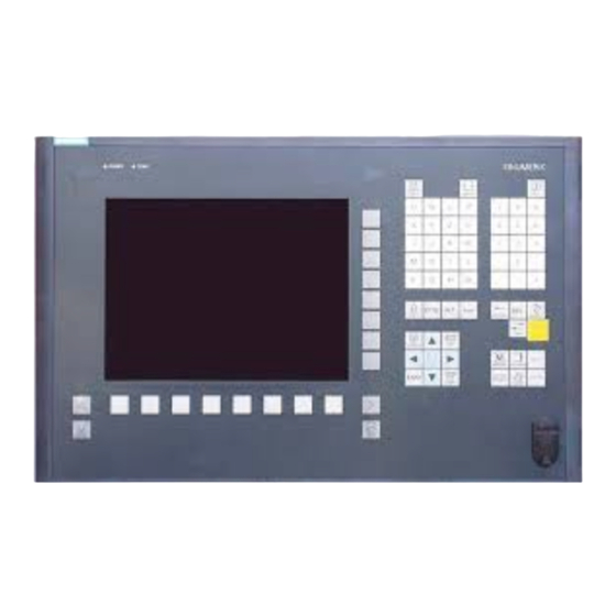
Page 22: Operator Panel Fronts
Introduction 2.2 Operator panel fronts Operator panel fronts 2.2.1 Overview Introduction The display (screen) and operation (e.g. hardkeys and softkeys) of the SINUMERIK Operate user interface use the operator panel front. In this example, the OP 010 operator panel front is used to illustrate the components that are available for operating the controller and machine tool. - Page 23 Introduction 2.2 Operator panel fronts Operator controls and indicators Alphabetic key group With the <Shift> key pressed, you activate the special characters on keys with double assign‐ ments, and write in the uppercase. Note: Depending on the particular configuration of your control system, uppercase letters are always written Numerical key group With the <Shift>...
-
Page 24: Keys Of The Operator Panel
Introduction 2.2 Operator panel fronts Manual operator components and networking; SINUMERIK 840D sl 2.2.2 Keys of the operator panel The following keys and key combinations are available for operation of the control and the machine tool. Keys and key combinations Function <ALARM CANCEL>... - Page 25 Introduction 2.2 Operator panel fronts <NEXT WINDOW> + <CTRL> + <SHIFT> ● Moves the cursor to the beginning of a program. ● Moves the cursor in the first row of the current column. ● Selects a contiguous selection from the current cursor position up to the target position.
- Page 26 Introduction 2.2 Operator panel fronts <Cursor up> ● Editing box Moves the cursor into the next upper field. ● Navigation – Moves the cursor in a table to the next cell upwards. – Moves the cursor upwards in a menu screen. <Cursor up>...
- Page 27 Introduction 2.2 Operator panel fronts <END> + <SHIFT> Moves the cursor to the last entry. Selects a contiguous selection from the cursor position up to the end of a program block. <END> + <CTRL> Moves the cursor to the last entry in the last line of the current column or to the end of a program.
- Page 28 Introduction 2.2 Operator panel fronts <CTRL> + <E> Calls the "Ctrl Energy" function. <CTRL> + <F> Opens the search dialog in the machine data and setting data lists, when loading and saving in the MDI editor as well as in the program manager and in the system data.
- Page 29 Introduction 2.2 Operator panel fronts <CTRL> + <ALT> + <D> Backs up the log files on the USB-FlashDrive. If a USB-FlashDrive is not inserted, then the files are backed-up in the manufacturer's area of the CF card. <SHIFT> + <ALT> + <D> Backs up the log files on the USB-FlashDrive.
- Page 30 Introduction 2.2 Operator panel fronts <Asterisk> Opens a directory with all of the subdirectories. <Tilde> Changes the sign of a number between plus and minus. <INSERT> ● Opens an editing window in the insert mode. Pressing the key again, exits the window and the entries are undone. ●...
-
Page 31: Machine Control Panels
2.3.1 Overview The machine tool can be equipped with a machine control panel by Siemens or with a specific machine control panel from the machine manufacturer. You use the machine control panel to initiate actions on the machine tool such as traversing an axis or starting the machining of a workpiece. - Page 32 Introduction 2.3 Machine control panels Overview EMERGENCY STOP button Installation locations for control devices (d = 16 mm) RESET Program control Operating modes, machine functions User keys T1 to T15 Traversing axes with rapid traverse override and coordinate switchover Spindle control with override switch Feed control with override switch (10) Keyswitch (four positions)
- Page 33 Introduction 2.3 Machine control panels Program control <SINGLE BLOCK> Single block mode on/off. <CYCLE START> The key is also referred to as NC Start. Execution of a program is started. <CYCLE STOP> The key is also referred to as NC Stop. Execution of a program is stopped.
- Page 34 Introduction 2.3 Machine control panels Traversing axes with rapid traverse override and coordinate switchover Axis keys Selects an axis. Direction keys Select the traversing direction. <RAPID> Traverse axis in rapid traverse while pressing the direction key. <WCS MCS> Switches between the workpiece coordinate system (WCS) and machine coordinate system (MCS).
-
Page 35: User Interface
Introduction 2.4 User interface User interface 2.4.1 Screen layout Overview Active operating area and mode Alarm/message line Channel operational messages Display for ● Active tool T ● Current feedrate F ● Active spindle with current status (S) ● Spindle utilization rate in percent Vertical softkey bar Display of active G functions, all G functions, H functions and input window for different functions (for example, skip blocks, program control) -
Page 36: Status Display
The machine is feeding energy back into the grid. The power rating display must be switched on in the status line. Note Information about configuration is available in the following reference: System Manual "Ctrl-Energy", SINUMERIK 840D sl / 828D Active operating area Display Description "Machine"... - Page 37 Introduction 2.4 User interface Display Description "Diagnosis" operating area "Start-up" operating area Active mode or submode Display Description "Jog" mode "MDA" mode "Auto" mode "Teach In" submode "Repos" submode "Ref Point" submode Alarms and messages Display Description Alarm display The alarm numbers are displayed in white lettering on a red background.
-
Page 38: Actual Value Window
Introduction 2.4 User interface Third line Display Description Display of channel status. If several channels are present on the machine, the channel name is also displayed. If only one channel is available, only the "Reset" channel status is displayed. With touch operation, you can change the channel here. Display of channel status: The program was aborted with "Reset". -
Page 39: T,F,S Window
Introduction 2.4 User interface The ENS coordinate system corresponds to the Work coordinate system, reduced by certain components ($P_TRAFRAME, $P_PFRAME, $P_ISO4FRAME, $P_CYCFRAME), which are set by the system when machining and are then reset again. By using the ENS coordinate system, jumps into the actual value display are avoided that would otherwise be caused by the additional components. - Page 40 Introduction 2.4 User interface The "T, S, F" window displays several spindles with a maximum of two utilization indicators. The grinding power display is integrated in the spindle speed display. The power bar is located in the Z plane behind the speed value. The following applies to the spindle display: ●...
-
Page 41: Current Block Display
Introduction 2.4 User interface Spindle data Display Meaning Spindle selection, identification with spindle number and main spindle Speed Actual value (when spindle turns, display increases) Setpoint (always displayed, also during positioning) Icon Spindle status Spindle not enabled Spindle is turning clockwise Spindle is turning counterclockwise Spindle is stationary Override... - Page 42 Introduction 2.4 User interface Display of the machining times If you set that the machining times are to be recorded in the settings for automatic mode, the measured times are shown at the end of the line as follows: Display Meaning Light green background Measured machining time of the program block (automatic mode) Green background...
-
Page 43: Operation Via Softkeys And Buttons
Introduction 2.4 User interface Editing a program directly In the Reset state, you can edit the current program directly. Press the <INSERT> key. Place the cursor at the relevant position and edit the program block. Direct editing is only possible for G code blocks in the NC memory, not for external execution. -
Page 44: Entering Or Selecting Parameters
Introduction 2.4 User interface General keys and softkeys When the symbol appears to the right of the dialog line on the user inter‐ face, you can change the horizontal softkey bar within an operating area. To do so, press the menu forward key. symbol indicates that you are in the expanded softkey bar. - Page 45 Introduction 2.4 User interface Procedure Keep pressing the <SELECT> key until the required setting or unit is se‐ lected. The <SELECT> key only works if there are several selection options available. - OR - Press the <INSERT> key. The selection options are displayed in a list. Select the required setting using the <Cursor down>...
-
Page 46: Pocket Calculator
Introduction 2.4 User interface + <*> Enter the multiplication characters using the <SHIFT> + <*> keys. + </> Enter the division character using the <SHIFT> + </> keys. Enter bracket expressions using the <SHIFT> + <(> and <SHIFT> + <)> keys. -
Page 47: Context Menu
Introduction 2.4 User interface - OR - Press the "Calculate" softkey. - OR - Press the <INPUT> key. The new value is calculated and displayed in the entry field of the calcu‐ lator. Press the "Accept" softkey. The calculated value is accepted and displayed in the entry field of the window. -
Page 48: Changing The User Interface Language
Introduction 2.4 User interface Operating area switchover You can display the operating area menu by touching the display symbol for the active operating area in the status display. Channel switchover You can switch over to the next channel by touching the channel display in the status display. -
Page 49: Entering Chinese Characters
Introduction 2.4 User interface Note Changing the language directly on the input screens You can switch between the user interface languages available on the controller directly on the user interface by pressing the key combination <CTRL + L>. 2.4.12 Entering Chinese characters Using the input editor IME (input method editor), you can select Asian characters where you enter the phonetic notation. - Page 50 Introduction 2.4 User interface Structure of the editor Figure 2-4 Example: Pinyin input Figure 2-5 Example: Zhuyin input Functions Pinyin input Entering Latin letters Editing the dictionary Dictionaries The simplified Chinese and traditional Chinese dictionaries that are supplied can be expanded: ●...
-
Page 51: Entering Asian Characters
Introduction 2.4 User interface 2.4.12.1 Entering Asian characters Precondition The control has been switched over to Chinese. Procedure Editing characters using the Pinyin method Open the screen form and position the cursor on the input field. Press the <Alt +S> keys. The editor is displayed. -
Page 52: Editing The Dictionary
Introduction 2.4 User interface Press the <BACKSPACE> softkey to delete entered phonetic notations. To select the associated character, press the <cursor right> or <cursor left> keys. Press the <input> key to enter the character. 2.4.12.2 Editing the dictionary Learning function of the input editor Requirement: The control has been switched over to Chinese. -
Page 53: Entering Korean Characters
Introduction 2.4 User interface The generated file should be saved in the UTF8 format under the name dictchs.txt (simplified Chinese) or dictcht.txt (traditional Chinese). Line structure: Pinyin phonetic spelling <TAB> Chinese characters <LF> Pinyin phonetic spelling <TAB> Chinese character1<TAB> Chinese character2 <TAB> … <LF>... - Page 54 Introduction 2.4 User interface Korean keyboard To enter Korean characters, you will need a keyboard with the keyboard assignment shown below. In terms of key layout, this keyboard is the equivalent of an English QWERTY keyboard and individual events must be grouped together to form syllables. Structure of the editor Functions Editing characters using a matrix...
- Page 55 Introduction 2.4 User interface Procedure Editing characters using the keyboard Open the screen form and position the cursor on the input field. Press the <Alt +S> keys. The editor is displayed. Switch to the "Keyboard - Matrix" selection box. Select the keyboard. Switch to the function selection box.
-
Page 56: Protection Levels
Introduction 2.4 User interface Press the <BACKSPACE> softkey to delete entered phonetic notations. Press the <input> key to enter the character into the input field. 2.4.14 Protection levels The input and modification of data in the control system is protected by passwords at sensitive places. -
Page 57: Online Help In Sinumerik Operate
Introduction 2.4 User interface Diagnostics operating area Protection level Keyswitch 3 (protection level 4) User (protection level 3) User (protection level 3) Manufacturer (protection level 1) User (protection level 3) Service (protection level 2) Start-up operating area Protection levels End user (protection level 3) Keyswitch 3 (protection level 4) - Page 58 Introduction 2.4 User interface ● Lists of the machine data ● Lists of the setting data ● Lists of the drive parameters ● List of all alarms Procedure Calling context-sensitive online help You are in an arbitrary window of an operating area. Press the <HELP>...
- Page 59 Introduction 2.4 User interface Press the <Follow reference> softkey or the <INPUT> key to display the help page for the selected topic. Press the "Current topic" softkey to return to the original help. Searching for a topic Press the "Search" softkey. The "Search in Help for: "...
- Page 60 Introduction 2.4 User interface Press the "Transfer to editor" softkey. The selected G function is taken into the program at the cursor position. Press the "Exit help" softkey again to close the help. Grinding Operating Manual, 05/2017, A5E40869190...
-
Page 61: Operating With Gestures
The following SINUMERIK operator panel fronts and SINUMERIK controllers can be operated with the SINUMERIK Operate Gen. 2 user interface: References OP 015 black / 019 black SINUMERIK 840D sl Operator Components and Networking Manual (https:// support.industry.siemens.com/cs/document/109736214) PPU 290.3 SINUMERIK 828D: PPU and Components (https://support.industry.siemens.com/cs/... -
Page 62: Touch-Sensitive User Interface
Operating with gestures 3.3 Finger gestures Touch-sensitive user interface Touch-sensitive user interface Do not wear thick gloves when operating the touch-sensitive glass user interface. Wear thin gloves made of cotton or gloves for touch-sensitive glass user interfaces with capacitive touch function. You will operate the touch-sensitive glass user interface on the Operator panel optimally with the following gloves. - Page 63 Operating with gestures 3.3 Finger gestures Flick vertically with one finger ● Scroll in lists (e.g. programs, tools, zero points) ● Scroll in files (e.g. NC programs) Flick vertically with two fingers ● Page-scroll in lists (e.g. NPV) ● Page-scroll in files (e.g. NC programs) Flick vertically with three fingers ●...
- Page 64 Operating with gestures 3.3 Finger gestures Pan with one finger ● Move graphic contents (e.g. simulation, mold making view) ● Move list contents Pan with two fingers ● Turn graphic contents (e.g. simulation, mold making view) Tapping and holding ● Open object for changing (e.g. NC block) Tapping with 2 index fingers - only with the 840D sl ●...
-
Page 65: Setting Up The Machine
Setting up the machine Switching on and switching off Startup When the control starts up, the main screen opens according to the operating mode specified by the machine manufacturer. In general, this is the main screen for the "REF POINT" submode. -
Page 66: Approaching A Reference Point
Setting up the machine 4.2 Approaching a reference point Approaching a reference point 4.2.1 Referencing axes Your machine tool can be equipped with an absolute or incremental path measuring system. An axis with incremental path measuring system must be referenced after the controller has been switched on –... -
Page 67: User Agreement
Setting up the machine 4.2 Approaching a reference point Press the <-> or <+> key. The selected axis moves to the reference point. If you have pressed the wrong direction key, the action is not accepted and the axes do not move. A symbol is shown next to the axis if it has been referenced. -
Page 68: Operating Modes
Setting up the machine 4.3 Operating modes Press the "User enable" softkey. The "User Agreement" window opens. It shows a list of all machine axes with their current position and SI position. Position the cursor in the "Acknowledgement" field for the axis in ques‐ tion. - Page 69 Setting up the machine 4.3 Operating modes Selecting "REF POINT" Press the <REF POINT> key. "REPOS" operating mode The "REPOS" operating mode is used for repositioning to a defined position. After a program interruption (e.g. to correct tool wear values) move the tool away from the contour in "JOG" mode.
-
Page 70: Modes Groups And Channels
Setting up the machine 4.3 Operating modes Selecting "Teach In" Press the <TEACH IN> key. 4.3.2 Modes groups and channels Every channel behaves like an independent NC. A maximum of one part program can be processed per channel. ● Control with 1channel One mode group exists. -
Page 71: Settings For The Machine
Setting up the machine 4.4 Settings for the machine Changing the channel Press the <CHANNEL> key. The channel changes over to the next channel. - OR - If the channel menu is available, a softkey bar is displayed. The active channel is highlighted. -
Page 72: Switching The Unit Of Measurement
Setting up the machine 4.4 Settings for the machine Press the "Act.vls. MCS" softkey. The machine coordinate system is selected. The title of the actual value window changes in the MCS. Machine manufacturer The softkey to changeover the coordinate system can be hidden. Please refer to the machine manufacturer's specifications. -
Page 73: Setting The Zero Offset
Setting up the machine 4.4 Settings for the machine Procedure Select the mode <JOG> or <AUTO> in the "Machine" operating area. Press the menu forward key and the "Settings" softkey. A new vertical softkey bar appears. Press the "Switch to inch" softkey. A prompt asks you whether you really want to switch over the unit of measurement. - Page 74 Setting up the machine 4.4 Settings for the machine Relative actual value Further, you also have the possibility of entering position values in the relative coordinate system. Note The new actual value is only displayed. The relative actual value has no effect on the axis positions and the active zero offset.
-
Page 75: Zero Offsets
Setting up the machine 4.5 Zero offsets Press the ">>", "REL act. vals" and "Set REL" softkeys to set position values in the relative coordinate system. Enter the new required position value for X, Y or Z directly in the actual value display (you can toggle between the axes with the cursor keys) and press the "Input"... - Page 76 Setting up the machine 4.5 Zero offsets After reference point approach, the actual value display for the axis coordinates is based on the machine zero of the machine coordinate system (Machine). The actual value display of the positions can also refer to the SZS coordinate system (settable zero system).
-
Page 77: Display Active Zero Offset
Setting up the machine 4.5 Zero offsets Coarse and fine offsets Every zero offset (G54 to G57, G505 to G599) consists of a coarse offset and a fine offset. You can call the zero offsets from any program (coarse and fine offsets are added together). You can save the workpiece zero, for example, in the coarse offset, and then store the offset that occurs when a new workpiece is clamped between the old and the new workpiece zero in the fine offset. -
Page 78: Displaying The Zero Offset "Overview
Setting up the machine 4.5 Zero offsets 4.5.3 Displaying the zero offset "overview" The active offsets or system offsets are displayed for all set-up axes in the "Work Offset - Overview" window. In addition to the offset (course and fine), the rotation, scaling and mirroring defined using this are also displayed. -
Page 79: Displaying And Editing Base Zero Offset
Setting up the machine 4.5 Zero offsets 4.5.4 Displaying and editing base zero offset The defined channel-specific and global base offsets, divided into coarse and fine offsets, are displayed for all set-up axes in the "Zero offset - Base" window. Machine manufacturer Please refer to the machine manufacturer's specifications. -
Page 80: Displaying And Editing Seat-Related Fine Offset
Setting up the machine 4.5 Zero offsets Press the "G54 … G599" softkey. The "Work offset - G54 ... G599 [mm]" window opens. Note The labeling of the softkeys for the settable work offsets varies, i.e. the settable work offsets configured on the machine are displayed (examples: G54 …... -
Page 81: Displaying And Editing Details Of The Zero Offsets
Setting up the machine 4.5 Zero offsets 4.5.7 Displaying and editing details of the zero offsets For each zero offset, you can display and edit all data for all axes. You can also delete zero offsets. For every axis, values for the following data will be displayed: ●... -
Page 82: Deleting A Zero Offset
Setting up the machine 4.5 Zero offsets Procedure Select the "Parameter" operating area. Press the "Zero offset" softkey. Press the "Active", "Base" or "G54…G599" softkey. The corresponding window opens. Place the cursor on the desired zero offset to view its details. Press the "Details"... -
Page 83: Deleting Seat-Related Fine Offsets
Setting up the machine 4.5 Zero offsets Procedure Select the "Parameter" operating area. Press the "Work offset" softkey. Press the "Overview", "Basis" or "G54…G599" softkey. Press the "Details" softkey. Position the cursor on the work offset you would like to delete. Press the "Clear offset"... -
Page 84: Measuring A Tool
Setting up the machine 4.6 Measuring a tool - OR - Press the "Delete all" softkey. A confirmation prompt is displayed as to whether you really want to delete the seat-related fine offsets. Note: The "Delete all" softkey is only available if seat-related work offsets have been set up. -
Page 85: Measure Grinding Tool Manually With The Work Piece Reference Point
Setting up the machine 4.6 Measuring a tool Measuring the reference points for the dresser Use the grinding wheel as reference point for manually measuring a dresser. 4.6.1.2 Measure grinding tool manually with the work piece reference point Reference point The workpiece edge serves as reference point when measuring length X and length Z. -
Page 86: Measure Grinding Tool Manually With The Dresser Reference Point
Setting up the machine 4.6 Measuring a tool Scratch the required edge using the tool. Press the "Set length" softkey. The tool length is calculated automatically and entered in the tool list. The cutting edge location is considered automatically. Note Active grinding tool Tool measurement is possible only with an active grinding tool. -
Page 87: Measuring The Dressing Tool Manually With The Grinding Tool Reference Point
Setting up the machine 4.6 Measuring a tool The tool is transferred to the "Measure: "Grinding Wheel" window. Select the "Dresser" entry in the "Reference point" selection field. Position the cursor in the "TR" field, press the "Select dresser" softkey, select the dresser for measuring the tool length and press the "OK"... -
Page 88: Surface Grinding
Setting up the machine 4.6 Measuring a tool Press the "Meas. tool" softkey. Press the "Measure dresser" softkey. Press the "Select dresser" softkey. The "Tool Selection" window opens. In the "Tool Selection" window, select the dressing tool that you want to measure and press the "OK"... -
Page 89: Measure Grinding Tool Manually With The Work Piece Reference Point
Setting up the machine 4.6 Measuring a tool Measuring grinding wheels and dressers You determine the tool offset data, i.e. the lengths or the positions of the tools, by making manual measurements (scratching). When measuring manually, traverse the tool manually to a defined reference point in order to determine the tool dimensions and positions in the Y and Z directions. -
Page 90: Measure Grinding Tool Manually With The Dresser Reference Point
Setting up the machine 4.6 Measuring a tool In the "Tool Selection" window, select the grinding tool that you want to measure and press the "OK" softkey. The cutting edge location must be entered in the tool list. - OR - Press the "Tool list"... - Page 91 Setting up the machine 4.6 Measuring a tool Procedure Select "JOG" mode in the "Machine" operating area. Press the "Meas. tool" softkey. Press the "Measure wheel" softkey. Press the "Select tool" softkey. The "Tool Selection" window opens. In the "Tool Selection" window, select the grinding tool that you want to measure and press the "OK"...
-
Page 92: Measuring The Dressing Tool Manually With The Grinding Tool Reference Point
Setting up the machine 4.6 Measuring a tool Note Active grinding tool Tool measurement is possible only with an active grinding tool. 4.6.2.4 Measuring the dressing tool manually with the grinding tool reference point Reference point A grinding wheel serves as reference point for the measurement of length X, Y or Z. Procedure Select "JOG"... -
Page 93: Measuring The Workpiece Zero
Setting up the machine 4.7 Measuring the workpiece zero Press the "Tool list" softkey, select in the tool list the grinding wheel for measuring the tool length and press the "In manual" softkey. The tool is transferred into the "Measure: Dresser" window. Press the "X", "Y"... - Page 94 Setting up the machine 4.7 Measuring the workpiece zero Requirement The requirement for measuring the workpiece is that a tool with known lengths is in the machining position. Procedure Select "JOG" mode in the "Machine" operating area. Press the "Workpiece zero" softkey. The "Measure: Edge"...
-
Page 95: Surface Grinding
Setting up the machine 4.7 Measuring the workpiece zero 4.7.2 Surface grinding 4.7.2.1 Overview The reference point for programming a workpiece is always the workpiece zero. The workpiece zero is determined on the workpiece edge. Manual measurement To measure the zero point manually, you need to traverse your tool manually up to the workpiece. -
Page 96: Monitoring Axis And Spindle Data
Setting up the machine 4.8 Monitoring axis and spindle data Press the "Select ZO" softkey to select a settable zero offset. In the "Zero Offset – G54 ... G599" window, select a zero offset, in which the zero point should be saved. Press the "In manual"... -
Page 97: Editing Spindle Data
Setting up the machine 4.8 Monitoring axis and spindle data Procedure Select the "Parameter" operating area. Press the "Setting data" softkey. The "Working Area Limitation" window appears. Place the cursor in the required field and enter the new values via the numeric keyboard. -
Page 98: Spindle Chuck Data
Setting up the machine 4.8 Monitoring axis and spindle data Procedure Select the "Parameter" operating area. Press the "Setting data" and "Spindle data" softkeys. The "Spindles" window opens. If you want to change the spindle speed, place the cursor on the "Maxi‐ mum", "Minimum", or "Spindle speed limitation at G96"... - Page 99 Setting up the machine 4.8 Monitoring axis and spindle data Counter-spindle You can measure either the forward edge or stop edge of the counter-spindle. The forward edge or stop edge automatically serves as the valid reference point when traversing the counter-spindle.
-
Page 100: Parameters, Spindle Chuck Data
Setting up the machine 4.8 Monitoring axis and spindle data Enter the desired parameter. The settings become active immediately. 4.8.3.2 Parameters, spindle chuck data Parameter Description Unit Main spindle Dimensions of the forward edge or stop edge ● Jaw type 1 ●... - Page 101 Setting up the machine 4.8 Monitoring axis and spindle data References More detailed information on cylinder error compensation can be found in the following reference: Extension Functions (FB2sl) Function Manual: ● Chapter: "Compensations (K3)" Precondition ● The option is set ●...
-
Page 102: Displaying Setting Data Lists
Setting up the machine 4.10 Handwheel assignment Displaying setting data lists You can display lists with configured setting data. Machine manufacturer Please refer to the machine manufacturer's specifications. Procedure Select the "Parameter" operating area. Press the "Setting data" and "Data lists" softkeys. The "Setting Data Lists"... - Page 103 Setting up the machine 4.10 Handwheel assignment Procedure Select the "Machine" operating area. Press the <JOG>, <AUTO> or <MDI> key. Press the menu forward key and the "Handwheel" softkey. The "Handwheel" window appears. A field for axis assignment will be offered for every connected handwheel. Position the cursor in the field next to the handwheel with which you wish to assign the axis (e.g.
-
Page 104: Mdi
Setting up the machine 4.11 MDI 4.11 4.11.1 Working in MDA In "MDI" mode (Manual Data Input mode), you can enter G-code commands or standard cycles block-by-block and immediately execute them for setting up the machine. You have the option of loading an MDI program or a standard program with the standard cycles directly into the MDI buffer from the program manager;... -
Page 105: Saving An Mda Program
Setting up the machine 4.11 MDI 4.11.3 Saving an MDA program Procedure Select the "Machine" operating area. Press the <MDI> key. The MDI editor opens. Create the MDI program by entering the G-code commands using the operator's keyboard. Press the "Store MDI" softkey. The "Save from MDI: Select storage location"... -
Page 106: Editing/Executing A Mdi Program
Setting up the machine 4.11 MDI 4.11.4 Editing/executing a MDI program Procedure Select the "Machine" operating area. Press the <MDI> key. The MDI editor opens. Enter the desired G-code commands using the operator’s keyboard. - OR - Enter a standard cycle, e.g. CYCLE62 (). Editing G-code commands/program blocks Edit G-code commands directly in the "MDI"... - Page 107 Setting up the machine 4.11 MDI Procedure Press the "Delete blocks" softkey. The program blocks displayed in the program window are deleted. Grinding Operating Manual, 05/2017, A5E40869190...
- Page 108 Setting up the machine 4.11 MDI Grinding Operating Manual, 05/2017, A5E40869190...
-
Page 109: Working In The Manual Mode
Working in the manual mode Overview Always use "JOG" mode when you want to set up the machine for the execution of a program or to carry out simple traversing movements on the machine: ● Synchronize the measuring system of the controller with the machine (reference point approach) ●... - Page 110 Working in the manual mode 5.2 Selecting a tool and spindle Display Meaning Number for additive and setup offset Sister tool (for replacement tool strategy) Spindles 1 and 2 (e.g. S1) Spindle selection for master spindle and identification with spindle num‐ Spindle M function Spindle off: Spindle is stopped CCW rotation: Spindle rotates counterclockwise...
-
Page 111: Selecting A Tool
Working in the manual mode 5.2 Selecting a tool and spindle 5.2.2 Selecting a tool Procedure Select the "JOG" operating mode. Press the "T, S, M" softkey. - OR - Enter the name or the number of the tool T. - OR - Press the "Select tool"... -
Page 112: Positioning The Spindle
Working in the manual mode 5.2 Selecting a tool and spindle Select a spindle direction of rotation (clockwise or counterclockwise) in the "Spindle M function" field. Press the <CYCLE START> key. The spindle rotates. Select the "Stop" setting in the "Spindle M function" field. Press the <CYCLE START>... -
Page 113: Traversing Axes
Working in the manual mode 5.3 Traversing axes Traversing axes 5.3.1 Traversing the axes You can traverse the axes in manual mode via the Increment or Axis keys or handwheels. During a traverse initiated from the keyboard, the selected axis moves at the programmed setup feedrate. -
Page 114: Traversing Axes By A Variable Increment
Working in the manual mode 5.4 Positioning axes Note When the controller is switched on, the axes can be traversed right up to the limits of the machine as the reference points have not yet been approached and the axes referenced. Emergency limit switches might be triggered as a result. -
Page 115: Default Settings For Manual Mode
Working in the manual mode 5.5 Default settings for manual mode The feedrate / rapid traverse override is active during traversing. Procedure If required, select a tool. Select the "JOG" operating mode. Press the "Positions" softkey. Enter the target position or target angle for the axis or axes to be traversed. Specify the desired value for the feedrate F. - Page 116 Working in the manual mode 5.5 Default settings for manual mode Procedure Select the "Machine" operating area. Press the <JOG> key. Press the menu forward key and the "Settings" softkey. The "Settings for manual operation" window is opened. See also Switching the unit of measurement (Page 72) Grinding Operating Manual, 05/2017, A5E40869190...
-
Page 117: Machining The Workpiece
Machining the workpiece Starting and stopping machining During execution of a program, the workpiece is machined in accordance with the programming on the machine. After the program is started in automatic mode, workpiece machining is performed automatically. Preconditions The following requirements must be met before executing a program: ●... -
Page 118: Selecting A Program
Machining the workpiece 6.2 Selecting a program Stopping machining Press the <CYCLE STOP> key. Machining stops immediately, individual blocks do not finish execution. At the next start, execution is resumed at the same location where it stopped. Canceling machining Press the <RESET> key. Execution of the program is interrupted. -
Page 119: Executing A Trial Program Run
Machining the workpiece 6.3 Executing a trial program run Executing a trial program run When testing a program, you can select that the system can interrupt the machining of the workpiece after each program block, which triggers a movement or auxiliary function on the machine. -
Page 120: Displaying The Current Program Block
Machining the workpiece 6.4 Displaying the current program block Press the <SINGLE BLOCK> key again, if the machining is not supposed to run block-by-block. The key is deselected again. If you now press the <CYCLE START> key again, the program is execu‐ ted to the end without interruption. - Page 121 Machining the workpiece 6.4 Displaying the current program block Highlighting of selected G code commands or keywords In the program editor settings, you can specify whether selected G code commands are to be highlighted in color. The following colors are used as standard: Display Meaning Blue font...
-
Page 122: Displaying A Basic Block
Machining the workpiece 6.4 Displaying the current program block 6.4.2 Displaying a basic block If you want precise information about axis positions and important G functions during testing or program execution, you can call up the basic block display. This is how you check, when using cycles, for example, whether the machine is actually traversing. -
Page 123: Correcting A Program
Machining the workpiece 6.5 Correcting a program Program example N10 subprogram P25 If, in at least one program level, a program is run through several times, a horizontal scroll bar is displayed that allows the run through counter P to be viewed in the righthand window section. The scroll bar disappears if multiple run-through is no longer applicable. -
Page 124: Repositioning Axes
Machining the workpiece 6.6 Repositioning axes Precondition A program must be selected for execution in "AUTO" mode. Procedure The program to be corrected is in the Stop or Reset mode. Press the "Prog. corr.” softkey. The program is opened in the editor. The program preprocessing and the current block are displayed. -
Page 125: Starting Execution At A Specific Point
Machining the workpiece 6.7 Starting execution at a specific point The feedrate/rapid traverse override is in effect. NOTICE Risk of collision When repositioning, the axes move with the programmed feedrate and linear interpolation, i.e. in a straight line from the current position to the interrupt point. Therefore, you must first move the axes to a safe position in order to avoid collisions. - Page 126 Machining the workpiece 6.7 Starting execution at a specific point Applications ● Stopping or interrupting program execution ● Specify a target position, e.g. during remachining Determining a search target ● User-friendly search target definition (search positions) – Direct specification of the search target by positioning the cursor in the selected program (main program) –...
-
Page 127: Continuing Program From Search Target
Machining the workpiece 6.7 Starting execution at a specific point Preconditions ● You have selected the desired program. ● The controller is in the reset state. ● The desired search mode is selected. NOTICE Risk of collision Pay attention to a collision-free start position and appropriate active tools and other technological values. -
Page 128: Defining An Interruption Point As Search Target
Machining the workpiece 6.7 Starting execution at a specific point Procedure Press the "Block search" softkey. Place the cursor on a particular program block. - OR - Press the "Find text" softkey, select the search direction, enter the search text and confirm with "OK". Press the "Start search"... -
Page 129: Parameters For Block Search In The Search Pointer
Machining the workpiece 6.7 Starting execution at a specific point If the "Higher level" and "Lower level" softkeys are available, use these to change the program level. Press the "Start search" softkey. The search starts. Your specified search mode will be taken into account. The search screen closes. - Page 130 Machining the workpiece 6.7 Starting execution at a specific point Search variants Block search mode Meaning With calculation It is used in order to be able to approach a target position in any circumstance (e.g. tool change position). - without approach The end position of the target block or the next programmed position is ap‐...
-
Page 131: Controlling The Program Run
Machining the workpiece 6.8 Controlling the program run Controlling the program run 6.8.1 Program control You can change the program sequence in the "AUTO" and "MDA" modes. Abbreviation/program con‐ Mode of operation trol The program is started and executed with auxiliary function outputs and dwell times. In this mode, the axes are not traversed. -
Page 132: Skip Blocks
Machining the workpiece 6.8 Controlling the program run Activating program control You can control the program sequence however you wish by selecting and clearing the relevant checkboxes. Display / response of active program controls If program control is activated, the abbreviation of the corresponding function appears in the status display as feedback response. -
Page 133: Overstore
Machining the workpiece 6.9 Overstore Skip levels, activate Select the corresponding checkbox to activate the desired skip level. Note The "Program Control - Skip Blocks" window is only available when more than one skip level is set up. Overstore With overstore, you have the option of executing technological parameters (for example, auxiliary functions, axis feed, spindle speed, programmable instructions, etc.) before the program is actually started. -
Page 134: Editing A Program
Machining the workpiece 6.10 Editing a program Press the <CYCLE START> key. The blocks you have entered are stored. You can observe execution in the "Overstore" window. After the entered blocks have been executed, you can append blocks again. You cannot change the operating mode while you are in overstore mode. Press the "Back"... -
Page 135: Searching In Programs
Machining the workpiece 6.10 Editing a program Calling the editor ● The editor is started via the "Program correction" softkey in the "Machine" operating area. You can directly change the program by pressing the <INSERT> key. ● The editor is called via the "Open" softkey as well as with the <INPUT> or <Cursor right> key in the "Program manager"... -
Page 136: Replacing Program Text
Machining the workpiece 6.10 Editing a program Precondition The desired program is opened in the editor. Procedure Press the "Search" softkey. A new vertical softkey bar appears. The "Search" window opens at the same time. Enter the desired search term in the "Text" field. Select "Whole words"... -
Page 137: Copying/Pasting/Deleting Program Blocks
Machining the workpiece 6.10 Editing a program Procedure Press the "Search" softkey. A new vertical softkey bar appears. Press the "Find and replace" softkey. The "Find and Replace" window appears. In the "Text" field, enter the term you are looking for and in the "Replace with"... - Page 138 Machining the workpiece 6.10 Editing a program Inserting program blocks The editor responds depending on what type of program block you insert. ● If you insert a G code, then the program block is directly inserted where the write mark is located.
-
Page 139: Renumbering A Program
Machining the workpiece 6.10 Editing a program If you have selected the "Automatic numbering" option for the editor, then the newly added program blocks are allocated a block number (N num‐ ber). The following rules apply: ● When creating a new program, the first line is allocated the "first block number". -
Page 140: Creating A Program Block
Machining the workpiece 6.10 Editing a program Enter the values for the first block number and the increment to be used for numbering. Press the "OK" softkey. The program is renumbered. Note ● If you only want to renumber a section, before the function call, select the program blocks whose block numbering you want to edit. - Page 141 Machining the workpiece 6.10 Editing a program Procedure Select the "Program Manager" operating area. Select the storage location and create a program or open a program. The program editor opens. Select the required program blocks that you wish to combine to form a block.
-
Page 142: Editor Settings
Machining the workpiece 6.10 Editing a program 6.10.7 Editor settings Enter the default settings in the "Settings" window that are to take effect automatically when the editor is opened. Defaults Setting Meaning Number automatically ● Yes: A new block number will automatically be assigned after every line change. - Page 143 Machining the workpiece 6.10 Editing a program Setting Meaning Cut only after selecting ● Yes: Parts of programs can only be cutout when program lines have been selected, i.e. the "Cutout" softkey only then is active. ● No: The program line, in which the cursor is positioned, can be cut out without having to select it.
- Page 144 Machining the workpiece 6.10 Editing a program Setting Meaning Highlight selected G Defines the display of G code commands. code commands ● No All G code commands are displayed in the standard color. ● Yes Selected G code commands or keywords are highlighted in color. Define the rules for the color assignment in the sleditorwidget.ini configuration file.
-
Page 145: Working With Dxf Files
Machining the workpiece 6.11 Working with DXF files Press the "Delete mach. times" softkey if you wish to delete the machining times. The machining times that have been determined are deleted from the editor as well as from the actual block display. If the machining times are saved to an ini file, then this file is also deleted. -
Page 146: Cleaning A Dxf File
Machining the workpiece 6.11 Working with DXF files 6.11.2.2 Cleaning a DXF file All contained layers are shown when a DXF file is opened. Layers that do not contain any contour- or position-relevant data can be shown or hidden. Requirement The DXF file is open in the Program Manager or in the editor. -
Page 147: Changing The Section
Machining the workpiece 6.11 Working with DXF files Press the "Details" and "Zoom -" softkeys if you wish to reduce the size of the segment. - OR - Press the "Details" and "Auto zoom" softkeys if you wish to automatically adapt the segment to the size of the window. -
Page 148: Rotating The View
Machining the workpiece 6.11 Working with DXF files 6.11.2.5 Rotating the view You can change the orientation of the drawing. Requirement The DXF file is open in the Program Manager or in the editor. Procedure Press the "Details" and "Rotate figure" softkeys. Press the "Arrow right", "Arrow left", "Arrow up", "Arrow down", "Arrow clockwise"... -
Page 149: Importing And Editing A Dxf File
Machining the workpiece 6.11 Working with DXF files Note Editing a geometric element You can use this function to make smaller changes to the geometry, e.g. for missing intersections. You should make larger changes in the input screen of the editor. Changes that you make with "Element edit"... -
Page 150: Assigning The Machining Plane
Machining the workpiece 6.11 Working with DXF files 6.11.3.3 Assigning the machining plane You can select the machining plane in which the contour created with the DXF reader should be located. Procedure The DXF file is opened in the editor. Press the "Select plane"... -
Page 151: Saving The Dxf File
Machining the workpiece 6.11 Working with DXF files Press the "Deselect range" softkey to undo the selection of the machining range. The DXF fie is reset to the original display. Delete selected ranges and elements of the DXF file Press the "Reduce" softkey. Delete range Press the "Delete range"... -
Page 152: Specifying A Reference Point
Machining the workpiece 6.11 Working with DXF files Procedure Reduce file according to your requirements and/or select the working areas. - OR - Press the "Back" and ">>" softkeys. Press the "Save DXF" softkey. Enter the required name in the "Save DXF Data" window and press "OK". The "Save As"... -
Page 153: Accepting Contours
Machining the workpiece 6.11 Working with DXF files - OR - Press the "Arc center" softkey to place the zero point at the center of an arc. - OR - Press the "Cursor" softkey to define the zero point at any cursor position. - OR - Press the "Free input"... - Page 154 Machining the workpiece 6.11 Working with DXF files Press the "From DXF file" and "Accept" softkeys. The "Open DXF File" window opens. Select a storage location and place the cursor on the relevant DXF file. You can, for example, use the search function to search directly for a DXF file in comprehensive folders and directories.
-
Page 155: Display And Edit User Variables
Machining the workpiece 6.12 Display and edit user variables 11. Press the ">>" and "Specify end point" softkeys if you do not want to accept the end point of the selected element. 12. Press the "Current position" softkey if you want to set the currently selected position as end point. -
Page 156: Global R Parameters
You may search for user data within the lists using any character string. References You will find additional information in the following references: Programming Manual Job Planning / SINUMERIK 840D sl / 828D 6.12.2 Global R parameters Global R parameters are arithmetic parameters, which exist in the control itself, and can be read or written to by all channels. - Page 157 Machining the workpiece 6.12 Display and edit user variables These comments are retained after the control is switched off. Number of global R parameters The number of global R parameters is defined in a machine data element. Range: RG[0]– RG[999] (dependent on the machine data). There are no gaps in the numbering within the range.
-
Page 158: R Parameters
Machining the workpiece 6.12 Display and edit user variables Press the "OK" softkey. ● A value of 0 is assigned to the selected global R parameters – or to all global R parameters. ● The selected comments are also deleted. 6.12.3 R parameters R parameters (arithmetic parameters) are channel-specific variables that you can use within... -
Page 159: Displaying Global User Data (Gud)
Machining the workpiece 6.12 Display and edit user variables Display comments Press the ">>" and "Display comments" softkeys. The "R parameters with comments " window opens. Press the "Display comments" softkey once again to return to the "R pa‐ rameters" window. Delete R variables Press the ">>"... - Page 160 Machining the workpiece 6.12 Display and edit user variables Example DEF NCK INT ZAEHLER1 = 10 GUDs are defined in files with the ending DEF. The following file names are reserved for this purpose: File name Meaning MGUD.DEF Definitions for global machine manufacturer data UGUD.DEF Definitions for global user data GUD4.DEF...
-
Page 161: Displaying Channel Guds
Machining the workpiece 6.12 Display and edit user variables 6.12.5 Displaying channel GUDs Channel-specific user variables Like the GUDs, channel-specific user variables are applicable in all programs for each channel. However, unlike GUDs, they have specific values. Definition A channel-specific GUD variable is defined with the following: ●... -
Page 162: Displaying Local User Data (Lud)
Machining the workpiece 6.12 Display and edit user variables 6.12.6 Displaying local user data (LUD) Local user variables LUDs are only valid in the program or subprogram in which they were defined. The controller displays the LUDs after the start of program processing. The display is available until the end of program processing. -
Page 163: Searching For User Variables
Machining the workpiece 6.12 Display and edit user variables Procedure Select the "Parameter" operating area. Press the "User variable" softkey. Press the "Program PUD" softkey. 6.12.8 Searching for user variables You can search for R parameters and user variables. Procedure Select the "Parameter"... - Page 164 Machining the workpiece 6.12 Display and edit user variables Procedure Select the "Start-up" operating area. Press the "System data" softkey. In the data tree, select the "NC data" folder and then open the "Definitions" folder. Select the file you want to edit. Double-click the file.
-
Page 165: Display G And Auxiliary Functions
Machining the workpiece 6.13 Display G and auxiliary functions 6.13 Display G and auxiliary functions 6.13.1 Selected G functions 16 selected G groups are displayed in the "G Function" window. Within a G group, the G function currently active in the controller is displayed. Some G codes (e.g. - Page 166 Machining the workpiece 6.13 Display G and auxiliary functions Group Meaning G group 7 Tool radius compensation (e.g. G40, G42) G group 8 Settable work offset (e.g. G54, G57, G500) G group 9 Offset suppression (e.g. SUPA, G53) G group 10 Exact stop - continuous-path mode (e.g.
-
Page 167: All G Functions
Machining the workpiece 6.13 Display G and auxiliary functions 6.13.2 All G functions All G groups and their group numbers are listed in the "G Functions" window. Within a G group, only the G function currently active in the controller is displayed. Additional information in the footer The following additional information is displayed in the footer: ●... -
Page 168: Auxiliary Functions
Machining the workpiece 6.13 Display G and auxiliary functions References ● Additional information is available in the following references: Function Manual, Basic Functions; Chapter, "Contour/orientation tolerance" ● For information about configuring the displayed G groups, refer to the following document: SINUMERIK Operate Commissioning Manual Procedure Select the "Machine"... -
Page 169: Displaying Superimpositions
Machining the workpiece 6.14 Displaying superimpositions Procedure Select the "Machine" operating area. Press the <JOG>, <MDA> or <AUTO> key. Press the "H functions" softkey. The "Auxiliary Functions" window opens. Press the "H functions" softkey again to hide the window again. 6.14 Displaying superimpositions You can display handwheel axis offsets or programmed superimposed movements in the... -
Page 170: Displaying Status Of Synchronized Actions
Machining the workpiece 6.15 Displaying status of synchronized actions Press the ">>" and "Superimposition" softkeys. The "Superimposition" window opens. Enter the required new minimum and maximum values for superimposi‐ tion and press the <INPUT> key to confirm your entries. Note: You can only change the superimposition values in "JOG"... - Page 171 Machining the workpiece 6.15 Displaying status of synchronized actions Note Numbers from the number range 1 to 254 can only be assigned once, irrespective of the identification number. Display of synchronized actions Using softkeys, you have the option of restricting the display to activated synchronized actions. Procedure Select the "Machine"...
-
Page 172: Displaying The Program Runtime And Counting Workpieces
Machining the workpiece 6.16 Displaying the program runtime and counting workpieces 6.16 Displaying the program runtime and counting workpieces To gain an overview of the program runtime and the number of machined workpieces, open the "Times, Counter" window. Machine manufacturer Please observe the information provided by the machine manufacturer. -
Page 173: Settings For The Automatic Mode
Machining the workpiece 6.17 Settings for the automatic mode Procedure Select the "Machine" operating area. Press the <AUTO> key. Press the "Times, Counter" softkey. The "Times, Counter" window opens. Select "Yes" under "Count workpieces" if you want to count completed workpieces. - Page 174 Machining the workpiece 6.17 Settings for the automatic mode You define whether the time determination function is activated while the workpiece is being machined. ● Off The time determination function is deactivated while machining a workpiece, i.e. the machining times are not determined. ●...
- Page 175 Machining the workpiece 6.17 Settings for the automatic mode See also Current block display (Page 41) Grinding Operating Manual, 05/2017, A5E40869190...
- Page 176 Machining the workpiece 6.17 Settings for the automatic mode Grinding Operating Manual, 05/2017, A5E40869190...
-
Page 177: Simulating Machining
Simulating machining Overview During simulation, the current program is calculated in its entirety and the result is displayed in graphical form. The result of programming is verified without moving the machine axes. Incorrectly programmed machining steps are detected at an early stage and incorrect machining on the workpiece is prevented. - Page 178 Simulating machining 7.1 Overview Programmable frames All frames and zero offsets are taken into account in the simulation. Note Manually swiveled axes Note that swivel movement in simulation and during simultaneous recording is also displayed when the axes are swiveled manually at the start. Simulation display For the simulation or simultaneous recording, the traversing paths, i.e.
- Page 179 Simulating machining 7.1 Overview In all views, a clock is displayed during graphical processing. The machining time is displayed in hours, minutes and seconds. It is approximately equal to the time that the program requires for processing including the tool change. Software options You require the "3D simulation of the finished part"...
-
Page 180: Simulation Before Machining Of The Workpiece
Simulating machining 7.2 Simulation before machining of the workpiece ● Changes to the toolcarrier or transformation data only become effective after Power On. ● Transformation change and swivel data record change are supported. However, a real kinematic change is not supported, where a swivel head is physically changed. Simulation before machining of the workpiece 7.2.1 Simulation before machining of the workpiece... -
Page 181: Simultaneous Recording Before Machining Of The Workpiece
Simulating machining 7.3 Simultaneous recording before machining of the workpiece Press "Start" softkey. The program execution is displayed graphically on the screen. The ma‐ chine axes do not move. To stop simulation, press the "Stop" softkey. - OR - Press the "Reset" softkey to cancel the simulation. Press the "Start"... -
Page 182: Starting Simultaneous Recording
Simulating machining 7.4 Simultaneous recording during machining of the workpiece 7.3.2 Starting simultaneous recording Procedure Load a program in the "AUTO" mode. Press the "Prog. ctrl." softkey and activate the checkboxes "PRT no axis movement" and "DRY run feedrate". The program is executed without axis movement. The programmed fee‐ drate is replaced by a dry run feedrate. -
Page 183: Program Control During Simulation
Simulating machining 7.5 Program control during simulation - OR Press the "Sim. rec." softkey again to stop the recording. Note Display of the traversing paths ● If you switch-off simultaneous recording during machining and then switch-on the function again at a later time, then the traversing paths generated in the intermediate time will not be displayed. -
Page 184: Simulating The Program Block By Block
Simulating machining 7.5 Program control during simulation Toggling between "Override +" and "Override -" Simultaneously press the <Ctrl> and <cursor down> or <cursor up> keys to toggle between the "Override +" and "Override -" softkeys. Selecting the maximum feedrate Press the <Ctrl> and <M> keys simultaneously to select the maximum fee‐ drate of 120%. -
Page 185: Different Views Of A Workpiece
Simulating machining 7.6 Different views of a workpiece Different views of a workpiece 7.6.1 Overview The following views are available: ● Side view ● Dressing view ● 3D view (with option) ● Face view - for cylindrical grinding ● Further side views - for surface grinding ●... -
Page 186: View
Simulating machining 7.6 Different views of a workpiece 7.6.4 3D view Displaying the 3D view Simultaneous recording or simulation is started. Press the "Other views" and "3D view" softkeys. Software option You require the option "3D simulation (finished part)" for the simulation. Changing the display You can enlarge, reduce, pan, and rotate the simulation graphic and the segment. -
Page 187: Machine Space (With "Collision Avoidance" Option)
Simulating machining 7.7 Editing the simulation display Press the "From the front" softkey if you wish to view from the front. - OR - Press the "From the rear" softkey if you wish to view from the rear. - OR - Press the "From the left"... -
Page 188: Editing And Adapting A Simulation Graphic
Simulating machining 7.8 Editing and adapting a simulation graphic Procedure Simultaneous recording is started. Press the ">>" softkey. The tool paths are displayed. Press the "'Delete tool path" softkey. All tool paths recorded up until now are deleted. Editing and adapting a simulation graphic 7.8.1 Enlarging or reducing the graphical representation Precondition... -
Page 189: Panning A Graphical Representation
Simulating machining 7.8 Editing and adapting a simulation graphic Note Selected section The selected sections and size changes are kept as long as the program is selected. 7.8.2 Panning a graphical representation Precondition The simulation or the simultaneous recording is started. Procedure Press a cursor key if you wish to move the graphic up, down, left, or right. -
Page 190: Modifying The Viewport
Simulating machining 7.8 Editing and adapting a simulation graphic Press the "Arrow right", "Arrow left", "Arrow up", "Arrow down", "Arrow clockwise" and "Arrow counterclockwise" softkeys to change the position of the workpiece. - OR - Keep the <Shift> key pressed and then turn the workpiece in the desired direction using the appropriate cursor keys. - Page 191 Simulating machining 7.8 Editing and adapting a simulation graphic Press one of the cursor keys to move the frame up, down, left or right. Press the "Accept" softkey to accept the selected section. Grinding Operating Manual, 05/2017, A5E40869190...
- Page 192 Simulating machining 7.8 Editing and adapting a simulation graphic Grinding Operating Manual, 05/2017, A5E40869190...
-
Page 193: Generating A G-Code Program
Generating a G-code program Graphical programming Functions The following functionality is available: ● Context-sensitive online help for every input window ● Support with contour input (geometry processor) Call and return conditions ● The G functions active before the cycle call and the programmable frame remain active beyond the cycle. - Page 194 Generating a G-code program 8.2 Program views Figure 8-1 Program view of a G code program Representation of the machining times Representation Meaning Light green background Measured machining time of the program block (automatic mode) Green background Measured machining time of the program block (automatic mode) Light blue background Estimated machining time of the program block (simulation) Blue background...
-
Page 195: Program Structure
Generating a G-code program 8.4 Basic principles Program structure G-code programs can always be freely programmed. The most important commands that are normally included are: ● Set a machining plane ● Call a tool (T and D) ● Call a zero offset ●... -
Page 196: Programming A Tool (T)
Generating a G-code program 8.5 Generating a G code program 8.4.2 Programming a tool (T) Calling a tool You are in a part program Press the "Select tool" softkey. The "Tool Selection" window opens. Position the cursor on the desired tool and press the "To program" softkey. The selected tool is loaded into the G-code editor. -
Page 197: Selection Of The Cycles Via Softkey
Generating a G-code program 8.6 Selection of the cycles via softkey Position the cursor on the folder "Part programs" and press the "New" softkey. The "New G Code Program" window opens. Enter the required name and press the "OK" softkey. The name can contain up to 28 characters (name + dot + 3-character extension). - Page 198 Generating a G-code program 8.6 Selection of the cycles via softkey Grinding Operating Manual, 05/2017, A5E40869190...
-
Page 199: Programming Technology Functions
Programming technology functions Programming contours Function The free contour programming allows you to create simple or complex contours. You define open or closed contours. A contour comprises separate contour elements, whereby at least two and up to 250 elements result in a defined contour. Radii, chamfers and tangential transitions are available as contour transition elements. -
Page 200: Creating A New Contour
Programming technology functions 9.1 Programming contours Contour element Icon Meaning Straight line in any direction Straight line with any gradient Arc right Circle Arc left Circle Pole Polar coordinates Finish contour End of contour definition The different colors of the icons indicate their status: Foreground Background Meaning... - Page 201 Programming technology functions 9.1 Programming contours The contours are saved at that position in the program where they are defined. Note Ensure that the contours are positioned after the program end identification! The first step in creating a contour is to specify a starting point. Enter the contour element. The contour processor then automatically defines the end of the contour.
-
Page 202: Creating Contour Elements
Programming technology functions 9.1 Programming contours Polar starting point Select the machining plane and press the "Pole" softkey. Enter the pole position in Cartesian coordinates. Enter the starting point for the contour in Polar coordinates. Enter any additional commands in G-code format, as required. Press the "Accept"... - Page 203 Programming technology functions 9.1 Programming contours For each contour element, you must parameterize a separate parameter screen. The coordinates for a horizontal or vertical line are entered in Cartesian format; however, for the contour elements Diagonal line and Circle/arc you can choose between Cartesian and Polar coordinates.
-
Page 204: Entering A Contour Element
Programming technology functions 9.1 Programming contours 9.1.3.1 Entering a contour element After you have created a new contour and specified the starting point, you can define the individual elements that make up the contour. Creating contour elements For each contour element, you must parameterize a separate parameter screen. The coordinates for a horizontal or vertical line are entered in Cartesian format;... -
Page 205: Cylindrical Grinding
Programming technology functions 9.1 Programming contours Press the "Accept" softkey. The programmed contour is transferred to the program view. If you want to display further parameters for certain contour elements, e.g. to enter additional commands, press the "All parameters" softkey. 9.1.3.2 Cylindrical grinding Parameter... -
Page 206: Surface Grinding
Programming technology functions 9.1 Programming contours Parameter Description Unit α1 Starting angle to X axis Degrees α2 Angle to the preceding element Degrees β1 End angle to Z axis Degrees β2 Opening angle Degrees Transition to next ele‐ Type of transition ment ●... - Page 207 Programming technology functions 9.1 Programming contours Parameter Description Unit α2 Angle to the preceding element Degrees Transition to next ele‐ Type of transition ment ● Radius ● Undercut ● Chamfer Radius Transition to following element - radius Undercut Form E Undercut size e.g.
- Page 208 Programming technology functions 9.1 Programming contours Parameter Description Unit Grinding allowance ● Grinding allowance to right of contour ● Grinding allowance to left of contour Additional commands Additional G-code commands Parameter Description Unit End point Z (abs or inc) End point Z ∅ (abs or end point Z (inc)) α1 Starting angle, e.g.
-
Page 209: Changing The Contour
Programming technology functions 9.1 Programming contours Parameter Description Unit Grinding allowance ● Grinding allowance to right of contour ● Grinding allowance to left of contour Additional commands Additional G-code commands Contour element "Pole" Parameters Description Unit Position pole (abs) Position pole (abs) Degrees Contour element "End"... -
Page 210: Contour Call (Cycle62)
Programming technology functions 9.1 Programming contours With the cursor, select the program block where you want to change the contour. Open the geometry processor. The individual contour elements are listed. Position the cursor at the position where a contour element is to be in‐ serted or changed. -
Page 211: Calling The Cycle
Programming technology functions 9.1 Programming contours 3. Subprogram The contour is located in a subprogram in the same workpiece. 4. Labels in the subprogram The contour is in a subprogram and is limited by the labels that have been entered. 9.1.5.2 Calling the cycle Procedure... -
Page 212: Set Dresser Coordinate System - Cycle435
Programming technology functions 9.2 Set dresser coordinate system - CYCLE435 Set dresser coordinate system - CYCLE435 9.2.1 Note regarding the dressing tool position The cycle to calculate the dressing tool position is not programmed using an input screen form in SINUMERIK Operate. Syntax CYCLE435(<_T>, <_DD>, <S_TA>, <S_DA>, <S_AD>, <S_AL>, <S_PVD>, <S_PVL>, <S_PD>, <S_PL>, <_AMODE>) -
Page 213: Form-Truing (Cycle495)
Programming technology functions 9.3 Form-truing (CYCLE495) Sequence In the cycle, the tool data of the tool that is not active is transferred into the cycle frame. This means that the dressing contour can be subsequently called relative to the geometry parameters. - Page 214 Programming technology functions 9.3 Form-truing (CYCLE495) Parameter Parameter Data type Meaning mask internal Machining type <_VARI> UNITS: Form-truing type Parallel to the axis Parallel to the contour TENS: Machining direction Pulling Possible with cutting edge posi‐ tions 1 to 4 Pushing Possible with cutting edge posi‐...
- Page 215 SD55884 $SCS_GRIND_CONT_BLANK_OFFSET References For additional information, please refer to the following documentation: ● SINUMERIK Operate (IM9) / SINUMERIK 840D sl Commissioning Manual ● SINUMERIK Operate (IH9) / SINUMERIK 828D Commissioning Manual Function With the cycle, you form-true grinding wheels using a dressing tool. A dressing tool must be selected as active tool.
- Page 216 Programming technology functions 9.3 Form-truing (CYCLE495) You have the option of form-truing either parallel with the axis or parallel with the contour: ● For form-truing parallel with the contour, the contour is moved along with each stroke. Taking into account the unmachined part (blank), contour segments can be omitted while machining.
-
Page 217: Oscillating Cycles (Cycle4071
Programming technology functions 9.4 Oscillating cycles (CYCLE4071 ... CYCLE4079) N10 G00 G90 N20 G01 X=2.5 Z=-37 F=100 N30 Z=-23.03906 F=100 N40 G03 X=0 Z=-23 CR=400 RND=0 F=50 N50 G03 X=0 Z=-3 CR=50 F=100 N60 G01 X=0 Z=-2.8 N70 Z=-0.2 N80 X=-1 F=50 N90 Z=2 F=100 N100 M17 Oscillating cycles (CYCLE4071 ... - Page 218 Programming technology functions 9.4 Oscillating cycles (CYCLE4071 ... CYCLE4079) Sequence 1. Start of the cycle at the current position of the oscillating axis. 2. Traversing of the infeed axis to the infeed depth at the start P1 <S_A> with the feedrate for infeed P5 <S_I>.
-
Page 219: Cycle4072 - Longitudinal Grinding With Infeed At The Reversal Point And Cancel Signal
Programming technology functions 9.4 Oscillating cycles (CYCLE4071 ... CYCLE4079) Program code N20 CYCLE4071(0.02,0.01,100,1,1,1000,2) N30 M30 9.4.3 CYCLE4072 - longitudinal grinding with infeed at the reversal point and cancel signal Syntax CYCLE4072(<S_GAUGE>, <S_A>, <S_B>, <S_W>, <S_U>, <S_I>, <S_K>, <S_H>, <S_A1>, <S_A2>) Parameters Parameter Data type... - Page 220 Programming technology functions 9.4 Oscillating cycles (CYCLE4071 ... CYCLE4079) 5. Traversing of the infeed axis to the infeed depth at the end P3 <S_B> with the feedrate for infeed P6 <S_I>. 6. Sparking out with the sparking-out time P5 <S_U>. 7.
- Page 221 Programming technology functions 9.4 Oscillating cycles (CYCLE4071 ... CYCLE4079) Resources As resources, the cycle uses a block-wide synchronized action and a synchronized action variable. The synchronized action is determined dynamically from the free area of the synchronized action range (CUS.DIR - 1 ..., CMA.DIR - 1000 ..., CST.DIR – 1199 ...). SYG_IS[1] is used as the synchronized action variable.
-
Page 222: Cycle4073 - Longitudinal Grinding With Continuous Infeed
Programming technology functions 9.4 Oscillating cycles (CYCLE4071 ... CYCLE4079) Program code N30 M30 9.4.4 CYCLE4073 - longitudinal grinding with continuous infeed Syntax CYCLE4073(<S_A>, <S_B>, <S_W>, <S_U>, <S_K>, <S_H>, <S_A1>, <S_A2>) Parameters Parameter Data type Meaning REAL Infeed depth at the start <S_A>... -
Page 223: Cycle4074 - Longitudinal Grinding With Continuous Infeed And Cancel Signal
Programming technology functions 9.4 Oscillating cycles (CYCLE4071 ... CYCLE4079) Example Oscillation with two strokes: Cycle parameters ● Infeed depth at the start: 0.02 mm ● Infeed depth at the end: 0.01 mm ● Stroke: 100 mm ● Sparking-out time: 1 s ●... - Page 224 Programming technology functions 9.4 Oscillating cycles (CYCLE4071 ... CYCLE4079) Parameters Parameter Data type Meaning STRING Cancel conditions for infeed: <S_GAUGE> 1. Number of a rapid input 2. Logical expression REAL Infeed depth at the start <S_A> REAL Infeed depth at the end <S_B>...
- Page 225 Programming technology functions 9.4 Oscillating cycles (CYCLE4071 ... CYCLE4079) Figure 9-3 Cancellation of the infeed from the end to the start Figure 9-4 Cancellation of the infeed from the start to the end Resources As resources, the cycle uses a block-wide synchronized action and a synchronized action variable.
-
Page 226: Cycle4075 - Surface Grinding With Infeed At The Reversal Point
Programming technology functions 9.4 Oscillating cycles (CYCLE4071 ... CYCLE4079) ● Stroke: 100 mm ● Sparking-out time: 1 s ● Transverse feedrate: 1000 mm/min ● Repetitions: 2 ● Oscillating and infeed axes: Standard geometry axes Cancel signal Rapid input 1 ($A_IN[1] ) Program code N10 T1 D1 N20 CYCLE4074("1",0.02,0.01,100,1,1000,2) - Page 227 Programming technology functions 9.4 Oscillating cycles (CYCLE4071 ... CYCLE4079) Parameter Data type Meaning REAL Total infeed depth <S_K> REAL Grinding width <S_A> REAL Feedrate for infeed <S_R> REAL Feedrate for transverse infeed <S_F> REAL Sparking-out time <S_P> AXIS Infeed axis (optional) <S_A1>...
- Page 228 Programming technology functions 9.4 Oscillating cycles (CYCLE4071 ... CYCLE4079) Figure 9-5 Total infeed depth reached with infeed at the second reversal point Figure 9-6 Total infeed depth reached with infeed at the first reversal point Example Oscillation with: ● 0.02 mm infeed depth at the start ●...
-
Page 229: Cycle4077 - Surface Grinding With Infeed At The Reversal Point And Cancel Signal
Programming technology functions 9.4 Oscillating cycles (CYCLE4071 ... CYCLE4079) Program code N10 T1 D1 N20 CYCLE4075(0.02,0.01,1,100,1,1000,1) N30 M30 9.4.7 CYCLE4077 - surface grinding with infeed at the reversal point and cancel signal Syntax CYCLE4077(<S_GAUGE>, <S_I>, <S_J>, <S_K>, <S_A>, <S_R>, <S_F>, <S_P>, <S_A1>, <S_A2>) Parameters Parameter... - Page 230 Programming technology functions 9.4 Oscillating cycles (CYCLE4071 ... CYCLE4079) Sequence 1. Start of the cycle at the current position of the oscillating axis. 2. Traversing of the infeed axis to the infeed depth at the start P2 <S_I> with the feedrate for infeed P6 <S_R>.
- Page 231 Programming technology functions 9.4 Oscillating cycles (CYCLE4071 ... CYCLE4079) Figure 9-8 Cancellation of the infeed at the start Resources As resources, the cycle uses a block-wide synchronized action and a synchronized action variable. The synchronized action is determined dynamically from the free area of the synchronized action range (CUS.DIR - 1 ..., CMA.DIR - 1000 ..., CST.DIR –...
-
Page 232: Cycle4078 - Surface Grinding With Continuous Infeed
Programming technology functions 9.4 Oscillating cycles (CYCLE4071 ... CYCLE4079) Example 2 Oscillation with: ● 0.02 mm infeed depth at the start ● 0.01mm infeed depth at the end ● Total infeed depth 1 mm ● 100 mm stroke ● Infeed feedrate 1 mm/min ●... - Page 233 Programming technology functions 9.4 Oscillating cycles (CYCLE4071 ... CYCLE4079) The specification of the infeed axis P8 <S_A1> and/or oscillating axis P9 <S_A2> are optional. If one or both parameters are not specified, the cycle uses the first two geometry axes of the channel.
-
Page 234: Cycle4079 - Surface Grinding With Intermittent Infeed
Programming technology functions 9.4 Oscillating cycles (CYCLE4071 ... CYCLE4079) ● Feedrate 1000 mm/min ● 1 second sparking-out time ● Standard geometry axes Program code N10 T1 D1 N20 CYCLE4078(20,10,100,100,1000,1) N30 M30 9.4.9 CYCLE4079 - surface grinding with intermittent infeed Syntax CYCLE4079(<S_I>, <S_J>, <S_K>, <S_A>, <S_R>, <S_F>, <S_P>, <S_A1>, <S_A2>) Parameters... - Page 235 Programming technology functions 9.4 Oscillating cycles (CYCLE4071 ... CYCLE4079) Sequence 1. Start of the cycle at the current position of the oscillating axis. 2. Traversing of the infeed axis to the infeed depth at the start P1 <S_I> with the feedrate for infeed P5 <S_R>.
-
Page 236: Aligning A Grinding Wheel (Cycle400)
Programming technology functions 9.5 Aligning a grinding wheel (CYCLE400) Figure 9-10 Total infeed depth reached with infeed at the first reversal point Example Oscillation with: ● 0.02 mm infeed depth at the start ● 0.01mm infeed depth at the end ●... -
Page 237: Calling The Cycle
Programming technology functions 9.5 Aligning a grinding wheel (CYCLE400) The maximum angular range when aligning is limited by the traversing range of the participating rotary axes. Technological limits are also placed on the angular range depending on the tool used. After aligning, the cutting-edge position is automatically adapted. Definition of angle ß... - Page 238 Programming technology functions 9.5 Aligning a grinding wheel (CYCLE400) Parameter Description Unit Machining the opposite ● Yes: Machining opposite the cutting edge position side ● No: Machining on the cutting edge position side Retraction ● Yes: Retract prior to swiveling ●...
-
Page 239: Grinding With A B Axis (Only For Cylindrical Grinding Machines)
Grinding with a B axis (only for cylindrical grinding machines) 10.1 Overview Cylindrical grinding machines with a B axis are supported by means of tool carriers. Figure 10-1 Example: Turret with four grinding spindles Tool carrier A separate tool carrier is set up for each grinding spindle. Each tool carrier has head kinematics with the B axis as first rotary axis. - Page 240 Grinding with a B axis (only for cylindrical grinding machines) 10.1 Overview β β Figure 10-2 Beta rotation Changing the cutting edge position The second rotary axis is controlled with the aid of the "Machining opposite" selection box, and the cutting edge position is changed via the CUTMOD function (e.g. internal grinding). Grinding Operating Manual, 05/2017, A5E40869190...
-
Page 241: T, S, M Window For Set-Up B Axis
Grinding with a B axis (only for cylindrical grinding machines) 10.2 T, S, M window for set-up B axis 10.2 T, S, M window for set-up B axis Alignment of the B axis Display Meaning Input of the tool (name or location number) You can select a tool from the tool list using the "Select tool"... -
Page 242: Measuring In Jog
Grinding with a B axis (only for cylindrical grinding machines) 10.3 Measuring in JOG Procedure Select the "JOG" operating mode. Press the "T, S, M" softkey. Enter the name or the number of the tool T. - OR - Press the "Select tool" softkey to open the tool list, position the cursor on the desired tool and press the "In manual"... -
Page 243: Manually Measuring The Grinding Tool (With B Axis)
Grinding with a B axis (only for cylindrical grinding machines) 10.3 Measuring in JOG Aligning the tools for the B axis ● TC Name of the swivel data set Note: If only one swivel data set is available, the "TC" selection field is omitted. ●... -
Page 244: Manually Measuring The Dresser (With B Axis)
Grinding with a B axis (only for cylindrical grinding machines) 10.3 Measuring in JOG Press the "Tool list" softkey, select in the tool list the grinding tool that you want to measure and press the "In manual" softkey. The tool is transferred to the "Measure: "Grinding Wheel" window. Select the "Dresser"... - Page 245 Grinding with a B axis (only for cylindrical grinding machines) 10.3 Measuring in JOG Procedure Select "JOG" mode in the "Machine" operating area. Press the "Meas. tool" softkey. Press the "Measure dresser" softkey. Dresser as tool Press the "Select dresser" softkey. The "Tool Selection"...
-
Page 246: Calibrating The Swivel Axis
Grinding with a B axis (only for cylindrical grinding machines) 10.3 Measuring in JOG 10.3.4 Calibrating the swivel axis Requirement The grinding wheel must be loaded before the calibration. Procedure Select "JOG" mode in the "Machine" operating area. Press the "Meas. tool" softkey. Press the "Swivel axis"... -
Page 247: Collision Avoidance (Only 840D Sl)
References More detailed explanations on the collision avoidance can be found in the following reference: SINUMERIK Operate (IM9) / SINUMERIK 840D sl Commissioning Manual; Function Manual, Special Functions (FB3): ● Section: "Kinematic chain (K7)"... -
Page 248: Set Collision Avoidance
Collision avoidance (only 840D sl) 11.2 Set collision avoidance Procedure Select the "Machine" operating area Press the <AUTO> key. Press the "Sim. rec." softkey. Press the "Other views" and "Machine area" softkeys. An active machine model (kinematic chains) is displayed for simultane‐ ous recording. - Page 249 Collision avoidance (only 840D sl) 11.2 Set collision avoidance Procedure Select the "Machine" operating area. Select the "JOG", "MDI" or "AUTO" mode. Press the menu forward key and the "Settings" softkey. Press the "Collision avoidance" softkey. The "Collision Avoidance" window opens. In the "Collision avoidance"...
- Page 250 Collision avoidance (only 840D sl) 11.2 Set collision avoidance Grinding Operating Manual, 05/2017, A5E40869190...
-
Page 251: Multi-Channel View
Multi-channel view 12.1 Multi-channel view The multi-channel view allows you to simultaneously view several channels in the following operating areas: ● "Machine" operating area ● "Program" operating area 12.2 Multi-channel view in the "Machine" operating area With a multi-channel machine, you have the option of simultaneously monitoring and influencing the execution of several programs. - Page 252 Multi-channel view 12.2 Multi-channel view in the "Machine" operating area Horizontal softkeys ● Block search When selecting the block search, the multi-channel view is kept. The block display is displayed as search window. ● Program control The "Program Control" window is displayed for the channels configured in the multi-channel view.
-
Page 253: Multi-Channel View For Large Operator Panels
Multi-channel view 12.3 Multi-channel view for large operator panels Displaying/hiding a multi-channel view Select the "Machine" operating area Select the "JOG", "MDA" or "AUTO" mode. Press the menu forward key and the "Settings" softkey. Press the "Multi-channel view" softkey. In the window "Settings for Multi-Channel View" in the selection box "View", select the required entry (e.g. - Page 254 Multi-channel view 12.3 Multi-channel view for large operator panels 3- or 4-channel view in the "Machine" operating area Use the multi-channel view settings to select the channels and specify the view. Channel view Display in the "Machine" operating area 3-channel view The following windows are displayed one above the other for each channel: ●...
-
Page 255: Setting The Multi-Channel View
Multi-channel view 12.4 Setting the multi-channel view Channel status When required, channel messages are displayed in the status display. Machine manufacturer Please refer to the machine manufacturer's specifications. 12.4 Setting the multi-channel view Setting Meaning View Here, you specify how many channels are displayed. ●... - Page 256 Multi-channel view 12.4 Setting the multi-channel view Procedure Select the "Machine" operating area. Select the "JOG", "MDA" or "AUTO" mode. Press the menu forward key and the "Settings" softkey. Press the "Multi-channel view" softkey. The "Settings for Multi-Channel View" window is opened. Set the multi-channel or single-channel view and define which channels are to be seen in the "Machine"...
-
Page 257: Manage Tools
Manage tools 13.1 Lists for the tool management All tools and also all magazine locations that have been created or configured in the NC are displayed in the lists in the Tool area. All lists display the same tools in the same order. When switching between the lists, the cursor remains on the same tool in the same screen segment. -
Page 258: Magazine Management
Manage tools 13.3 Tool types Search functions You have the option of searching through the lists according to the following objects: ● Tool ● Magazine location ● Empty location 13.2 Magazine management Depending on the configuration, the tool lists support a magazine management. Magazine management functions ●... - Page 259 Manage tools 13.3 Tool types Tool types Figure 13-1 Example for the list of favorites (cylindrical grinding) Figure 13-2 Example for the list of favorites (surface grinding) Figure 13-3 Tools listed in the "New Tool - Grinding Tools" window (cylindrical grinding) Grinding Operating Manual, 05/2017, A5E40869190...
-
Page 260: Tool Dimensioning
Manage tools 13.4 Tool dimensioning Figure 13-4 Tools listed in the "New Tool - Grinding Tools" window (surface grinding) Figure 13-5 Available tools in the "New Tool - Special Tools" window 13.4 Tool dimensioning This section provides an overview of the dimensioning of tools. Grinding Operating Manual, 05/2017, A5E40869190... - Page 261 Manage tools 13.4 Tool dimensioning Tool types Figure 13-6 Grinding disk Figure 13-7 3D-probe Machine manufacturer The tool length is measured to the center of the ball or to the ball circumference. Please refer to the machine manufacturer's specifications. Note A 3D-probe must be calibrated before use.
-
Page 262: Tool List
Manage tools 13.5 Tool list 13.5 Tool list 13.5.1 Tool list All parameters and functions that are required to create and set up the tools are displayed in the tool list. Each tool is uniquely identified by the tool identifier and the sister tool number. For the tool display, i.e. - Page 263 Please refer to the machine manufacturer's specifications. References Information on the configuration and setting up of the tool list can be found in the following references: Commissioning Manual SINUMERIK Operate (IM9) / SINUMERIK 840D sl Icons in the tool list Icon/ Meaning...
-
Page 264: Additional Data
Manage tools 13.5 Tool list Icon/ Meaning Marking Green frame The tool is preselected. Magazine/location number Green double arrow The magazine location is positioned at the change po‐ sition. Gray double arrow The magazine location is positioned at the load position. Red cross The magazine location is disabled. -
Page 265: Creating A New Tool
Manage tools 13.5 Tool list Tool type Additional parameters 714 Star-type probe Geometry length (length X, length Y, length Z) Wear length (Δ length X, Δ length Y, Δ length Z) Adapter length (length X, length Y, length Z) Offset angle (angle) Ball diameter (Ø) 725 Calibration tool Geometry length (length X, length Y, length Z) - Page 266 Manage tools 13.5 Tool list To do this, you can select an empty magazine location or the NC tool memory outside of the magazine. You may also position the cursor on an existing tool in the area of the NC tool memory. Data from the displayed tool will not be overwritten. Press the "New tool"...
-
Page 267: Measuring A Tool - Tool List
Manage tools 13.5 Tool list Commissioning Manual SINUMERIK Operate (IM9) / SINUMERIK 840D sl 13.5.4 Measuring a tool - tool list You can measure the tool offset data for the individual tools directly from the tool list. Note Tool measurement is only possible with an active tool. -
Page 268: Deleting A Tool
Manage tools 13.5 Tool list Procedure The tool list opens. Position the cursor on the tool for which you would like to store more cutting edges. Press the "Cutting edges" softkey in the "Tool list". Press the "New cutting edge" softkey. A new data set is stored in the list. -
Page 269: Loading And Unloading Tools
Manage tools 13.5 Tool list 13.5.7 Loading and unloading tools You can load and unload tools to and from a magazine via the tool list. When a tool is loaded, it is taken to a magazine location. When it is unloaded, it is removed from the magazine and stored in the tool list. -
Page 270: Selecting A Magazine
Manage tools 13.5 Tool list Select the required loading point and confirm with "OK". Unloading tools Place the cursor on the tool that you would like to unload from the mag‐ azine and press the "Unload" softkey. Select the required load point in the "Load Point Selection" window. Confirm your selection with "OK". -
Page 271: Code Carrier Connection (Only 840D Sl)
The magazine selection behavior with multiple magazines can be configured in different ways. Machine manufacturer Please refer to the machine manufacturer's specifications. References For a description of configuration options, refer to the Commissioning Manual SINUMERIK Operate (IM9) / SINUMERIK 840D sl 13.5.9 Code carrier connection (only 840D sl) 13.5.9.1 Overview You have the option of configuring a code carrier connection. -
Page 272: Managing Tools On A Code Carrier
Manage tools 13.5 Tool list 13.5.9.2 Managing tools on a code carrier With a code carrier connection, in the list of favorites, there is also a tool available. Figure 13-8 New tool from code carrier in the list of favorites Creating a new tool from code carrier The tool list is opened. - Page 273 The deletion of the tool can be set differently, i.e. the "On code carrier" softkey is not available. References A description of the configuration options can be found in the following reference: Commissioning Manual SINUMERIK Operate (IM9) / SINUMERIK 840D sl Grinding Operating Manual, 05/2017, A5E40869190...
-
Page 274: Managing A Tool In A File
Manage tools 13.5 Tool list 13.5.10 Managing a tool in a file If, in the tool list settings, the "Permit tool in/out file" option is activated, then an additional entry is available in the list of favorites. Figure 13-9 New tool from file in the list of favorites Creating a new tool from file The tool list is opened. - Page 275 Manage tools 13.5 Tool list The tool creation sequence can be defined differently. Unloading a tool in a file The tool list is opened. Place the cursor on the tool that you would like to unload from the mag‐ azine and press the "Unload" and "In file" softkeys. Navigate to the required directory and press the "OK"...
-
Page 276: Tool Wear
Manage tools 13.6 Tool wear 13.6 Tool wear 13.6.1 Tool wear All parameters and functions that are required during operation are contained in the tool wear list. Tools that are in use for long periods are subject to wear. You can measure this wear and enter it in the tool wear list. - Page 277 Manage tools 13.6 Tool wear Tool parameters Column heading Meaning Location Magazine/location number ● The magazine location numbers The magazine number is specified first, followed by the location number in the magazine. If there is only one magazine, only the location number is displayed. ●...
- Page 278 Manage tools 13.6 Tool wear Column heading Meaning Tool life Tool life Workpiece count Number of workpieces Wear Tool wear Wear, summed offset * *Parameter depends on selection in TC Setpoint Setpoint for tool life, workpiece count, or wear Prewarning limit Specification of the tool life, workpiece count or wear at which a warning is displayed.
-
Page 279: Reactivating A Tool
When the "Reactivation of all monitoring types" function is configured, all the monitoring types set in the NC for a tool are reset during reactivation. Machine manufacturer Please refer to the machine manufacturer's specifications. References Commissioning Manual SINUMERIK Operate (IM9) / SINUMERIK 840D sl Grinding Operating Manual, 05/2017, A5E40869190... -
Page 280: Tool Data Oem
Manage tools 13.7 Tool data OEM Multiple load points If you have configured several loading points for a magazine, then the "Load Point Selection" window appears after pressing the "Load" softkey. Select the required load point and confirm with the "OK" softkey. 13.7 Tool data OEM You have the option of configuring the list according to your requirements. -
Page 281: Magazine
Function Manual, Extended Functions W4: Grinding-specific tool offset and monitoring functions / SINUMERIK 840D sl ● Refer to the following document for more information on configuring OEM tool data: Commissioning Manual SINUMERIK Operate (IM9) / SINUMERIK 840D sl Procedure Select the "Parameter" operating area. - Page 282 Manage tools 13.8 Magazine Tool parameters Column heading Meaning Location Magazine/location number ● Magazine location numbers The magazine number is specified first, followed by the location number in the magazine. If there is only one magazine, only the location number is displayed. ●...
-
Page 283: Positioning A Magazine
Manage tools 13.8 Magazine Further parameters If you have set up unique cutting edge numbers, these are displayed in the first column. Column heading Meaning D no. Unique cutting edge number Cutting edge number Magazine list icons Icon/ Meaning marking Tool type Red cross The tool is disabled. -
Page 284: Relocating A Tool
Manage tools 13.8 Magazine Procedure The magazine list is opened. Place the cursor on the magazine location that you want to position onto the load point. Press the "Position magazine" softkey. The magazine location is positioned on the loading point. Multiple load points If you have configured several loading points for a magazine, then the "Loading Point Selection"... -
Page 285: Deleting/Unloading/Loading/Relocating All Tools
Manage tools 13.8 Magazine Several magazines If you have set up several magazines, then the "...relocate from magazine... location... to..." window appears after pressing the "Relocate" softkey. Select the desired magazine and location, and confirm your selection with "OK" to load the tool. -
Page 286: Sorting Tool Management Lists
Manage tools 13.10 Filtering the tool management lists 13.9 Sorting tool management lists When you are working with many tools, with large magazines or several magazines, it is useful to display the tools sorted according to different criteria. Then you will be able to find a specific tool more easily in the lists. - Page 287 Please refer to the machine manufacturer's specifications. References A description of the configuration options is provided in SINUMERIK Operate (IM9) / SINUMERIK 840D sl Commissioning Manual Procedure Select the "Parameter" operating area. Press the "Tool list", "Tool wear" or "Magazine" softkey.
-
Page 288: Specific Search In The Tool Management Lists
You can enter the location type as numerical value or as text depending on the particular configuration. Machine manufacturer Please refer to the machine manufacturer's specifications. References For a description of configuration options, refer to the Commissioning Manual SINUMERIK Operate (IM9) / SINUMERIK 840D sl Grinding Operating Manual, 05/2017, A5E40869190... -
Page 289: Tool Details
Manage tools 13.12 Tool details Procedure Select the "Parameter" operating area. Press the "Tool list", "Tool wear" or "Magazine" softkey. Press the ">>" and "Search" softkeys. Press the "Tool" softkey if you wish to search for a specific tool. - OR - Press the "Magazine location"... -
Page 290: Tool Data
Manage tools 13.12 Tool details Procedure The tool list, the wear list, the OEM tool list or the magazine is open. Position the cursor to the desired tool. If you are in the tool list or in the magazine, press the ">>" and "Details" softkey. -
Page 291: Grinding Data
Manage tools 13.12 Tool details Parameter Meaning Tool being changed Tool in fixed location The tool is permanently assigned to this magazine location Tool has been in use Tool size Standard Tool does not require an additional location in a magazine. Oversize The tool occupies two half locations left, two half locations right, one half location top and one half location bottom in a magazine. -
Page 292: Cutting Edge Data
Manage tools 13.12 Tool details 13.12.4 Cutting edge data The "Tool Details" window provides the following data on the selected tool when the "Cutting edge data" softkey is active. Parameter Description Magazine location The magazine number is specified first, followed by the location number in the magazine. If there is only one magazine, only the location number is displayed. -
Page 293: Changing A Tool Type
Manage tools 13.14 Working with Multitool Parameter Meaning Monitoring type T - tool life C - count W - wear The wear monitoring is configured via machine data. Please note the specifications of the machine manufacturer. Actual value Tool life, count and wear Actual value for tool life, count or wear Setpoint Tool life, count and wear... -
Page 294: Tool List For Multitool
Manage tools 13.14 Working with Multitool The multitool itself has two or more locations to accept tools. The tools are directly mounted on the multitool. The multitool is located at a location in the magazine. Geometrical arrangement of the tools on the multitool The geometrical arrangement of the tools is defined by the clearance between the locations on the multitool. -
Page 295: Create Multitool
Manage tools 13.14 Working with Multitool 13.14.2 Create multitool The multitool can be selected in the list of special tool types. Figure 13-11 Selection list for special tools with multitool Procedure The tool list is opened. Position the cursor at the position where the tool is to be created. For this, you can select an empty magazine location or the NC tool storage outside the magazine. -
Page 296: Equipping Multitool With Tools
Manage tools 13.14 Working with Multitool The multitool is created in the tool list. Note The tool creation sequence can be defined differently. Machine manufacturer Please observe the information provided by the machine manufacturer. 13.14.3 Equipping multitool with tools Precondition A multitool has been created in the tool list. -
Page 297: Removing A Tool From Multitool
Manage tools 13.14 Working with Multitool Position the cursor on the tool that you want to load into the multi‐ tool. Press the "Load" and "Multitool" softkeys. The "Load on..." window opens. Select the required multitool and the multitool location into which you wish to load the tool. -
Page 298: Deleting Multitool
Manage tools 13.14 Working with Multitool 13.14.5 Deleting multitool Procedure The tool list opens. Position the cursor on the multitool that you wish to delete. Press the "Delete multitool" softkey. The multitool with all of the tools that are located in it is deleted. 13.14.6 Loading and unloading multitool Procedure... -
Page 299: Positioning Multitool
Manage tools 13.14 Working with Multitool Unloading a multitool Position the cursor on the multitool that you wish to unload from the magazine. Press the "Unload" softkey. The multitool is removed from the magazine and is saved in the NC memory at the end of the tool list. 13.14.7 Positioning multitool You can position a magazine. -
Page 300: Reactivating A Multitool
Manage tools 13.14 Working with Multitool Press the "Relocate" softkey. The "... relocate from location ... to location ..." window is displayed. The "Location" field is pre-assigned with the number of the first empty magazine location. Press the "OK" softkey to relocate the multitool to the suggested magazine location. - Page 301 When the "Reactivation of all monitoring types" function is configured, all the monitoring types set in the NC for a tool are reset during reactivation. Machine manufacturer Please observe the information provided by the machine manufacturer. References HMI sl / SINUMERIK 840D sl Commissioning Manual Grinding Operating Manual, 05/2017, A5E40869190...
-
Page 302: Settings For Tool Lists
Please refer to the machine manufacturer's specifications. References For further information about configuring the settings, please refer to the following references: Commissioning Manual SINUMERIK Operate (IM9) / SINUMERIK 840D sl Procedure Select the "Parameter" operating area. Press the "Tool list", "Tool wear" or "Magazine" softkey. - Page 303 Manage tools 13.15 Settings for tool lists Press the "Continue" and "Settings" softkeys. Activate the corresponding check box for the desired setting. Grinding Operating Manual, 05/2017, A5E40869190...
- Page 304 Manage tools 13.15 Settings for tool lists Grinding Operating Manual, 05/2017, A5E40869190...
-
Page 305: Managing Programs
Managing programs 14.1 Overview You can access programs at any time via the Program Manager for execution, editing, copying, or renaming. Programs that you no longer require can be deleted to release their storage space. NOTICE Execution from USB-FlashDrive Direct execution from a USB-FlashDrive is not recommended. There is no protection against contact problems, falling out, breakage through knocking or unintentional removal of the USB-FlashDrive during operation. - Page 306 Managing programs 14.1 Overview Data exchange with other workstations You have the following options for exchanging programs and data with other workstations: ● USB drives (e.g. USB-FlashDrive) ● Network drives ● FTP drives Choosing storage locations In the horizontal softkey bar, you can select the storage location that contains the directories and programs that you want to display.
- Page 307 Managing programs 14.1 Overview Figure 14-1 Program directory in the program manager The plus sign in front of empty directories is removed after they have been read for the first time. The directories and programs are always listed complete with the following information: ●...
-
Page 308: Nc Memory
Managing programs 14.1 Overview Figure 14-2 Active program shown in green 14.1.1 NC memory The complete NC working memory is displayed along with all workpieces, main programs and subprograms as well as dressing programs. You can create further subdirectories here. Procedure Select the "Program manager"... -
Page 309: Creating An Nc Directory On The Local Drive
Managing programs 14.1 Overview Procedure Select the "Program manager" operating area. Press the "Local drive" softkey. 14.1.3 Creating an NC directory on the local drive On the local drive, you have the option of mapping the directory structure of the NC memory. This also simplifies the search sequence. -
Page 310: Ftp Drive
Managing programs 14.1 Overview Partitioned USB-FlashDrive (only 840D sl and TCU) If the USB-FlashDrive has several partitions, these are displayed in a tree structure as a subtree (01,02,...). For EXTCALL calls, enter the partition (e.g. USB:/02/... or //ACTTCU/FRONT/02/... or // ACTTCU/FRONT,2/... -
Page 311: Opening And Closing The Program
Managing programs 14.2 Opening and closing the program Procedure Select the "Program manager" operating area. Press the "FTP" softkey. When selecting the FTP drive for the first time, a login window is displayed. Enter the user name and password and press the "OK" softkey to log into the FTP server. -
Page 312: Executing A Program
Managing programs 14.3 Executing a program - OR - Press the <INPUT> key. - OR - Press the <Cursor right> key. - OR - Double-click the program. The selected program is opened in the "Editor" operating area. Now make the necessary program changes. Press the "NC Select"... - Page 313 Managing programs 14.3 Executing a program For workpieces, the workpiece directory must contain a program with the same name. This program is automatically selected for execution (e.g. when you select the workpiece SHAFT.WPD, the main program SHAFT.MPF is automatically selected). If an INI file of the same name exists (e.g.
-
Page 314: Creating A Directory / Program / Job List
Managing programs 14.4 Creating a directory / program / job list 14.4 Creating a directory / program / job list 14.4.1 Creating a new directory Directory structures help you to manage your program and data transparently. At all archive locations, you can create subdirectories for this purpose in a directory. In a subdirectory, in turn, you can create programs and then create program blocks for them. -
Page 315: Creating A New Workpiece
Managing programs 14.4 Creating a directory / program / job list 14.4.2 Creating a new workpiece You can set up various types of files such as main programs, initialization files, tool offsets, etc. in a workpiece. Note Workpiece directories You have the option of nesting tool directories. You must note that the length of the call line is restricted. -
Page 316: Creating A New Dressing Program
Managing programs 14.4 Creating a directory / program / job list Procedure Select the "Program manager" operating area. Select the desired storage location and position the cursor on the folder, in which you would like to store the program. Press the "New" softkey. The "New G Code Program"... -
Page 317: Storing Any New File
Managing programs 14.4 Creating a directory / program / job list Enter the desired program name and press the "OK" softkey. Program names may be a maximum of 24 characters long. You can use all letters (with the exception of special characters, language- specific special characters, Asian or Cyrillic characters), numbers and underscores (_). -
Page 318: Creating A Job List
Managing programs 14.4 Creating a directory / program / job list Press the "New" and "Any" softkeys. The "Any New Program" window appears Select a file type from the "Type" selection field (for example, "Definitions GUD") and enter the name of the file to be created when you have se‐ lected a workpiece directory in the NC memory. -
Page 319: Creating A Program List
Comments are identified in the job list by ";" at the start of the line or by round brackets. Template You can select a template from Siemens or the machine manufacturer when creating a new job list. Executing a workpiece If the "Select"... -
Page 320: Creating Templates
Managing programs 14.5 Creating templates Procedure Select the "Program manager" operating area. Press the menu forward key and the "Program list" softkey. The "Prog.-list" window opens. Place the cursor in the desired line (program number). Press the "Select program" softkey. The "Programs"... -
Page 321: Searching Directories And Files
Managing programs 14.6 Searching directories and files Procedure Select the "Start-up" operating area. Press the "System data" softkey. Position the cursor on the file that you wish to store as a template and press the "Copy" softkey. Select the directory in which you want to store the data - "Part programs" or "Workpieces"... -
Page 322: Displaying The Program In The Preview
Managing programs 14.7 Displaying the program in the Preview. Procedure Select the "Program Manager" operating area. Select the storage location in which you wish to perform the search and then press the ">>" and "Search" softkeys. The "Find File" window opens. Enter the desired search term in the "Text"... -
Page 323: Selecting Several Directories/Programs
Managing programs 14.8 Selecting several directories/programs 14.8 Selecting several directories/programs You can select several files and directories for further processing. When you select a directory, all directories and files located beneath it are also selected. Note Selected files If you have selected individual files in a directory, then this selection is canceled when the directory is closed. -
Page 324: Copying And Pasting A Directory/Program
Managing programs 14.9 Copying and pasting a directory/program Selecting via keys Key combination Meaning Renders or expands a selection. You can only select individual elements. Renders a consecutive selection. A previously existing selection is canceled. Selecting with the mouse Key combination Meaning Left mouse Click on element: The element is selected. - Page 325 Managing programs 14.9 Copying and pasting a directory/program Copied files or directories can be pasted in a different location. Note You can only paste directories on local drives and on USB or network drives. Note Write protection If the current directory is write-protected for the user, then the function is not offered. Note When you copy directories, any missing endings are added automatically.
-
Page 326: Deleting A Program/Directory
Managing programs 14.10 Deleting a program/directory Press the "OK" or "Overwrite all" softkey if you want to overwrite existing directories/programs. - OR - Press the "No overwriting" softkey if you do not want to overwrite already existing directories/programs. - OR - Press the "Skip"... -
Page 327: Changing File And Directory Properties
Managing programs 14.11 Changing file and directory properties Press the "OK" softkey to delete the program/directory. - OR -. Press the "Cancel" softkey to cancel the process. 14.11 Changing file and directory properties Information on directories and files can be displayed in the "Properties for ..." window. Information on the creation date is displayed near the file's path and name. -
Page 328: Creating Drives
Managing programs 14.12 Creating drives Procedure Select the program manager. Choose the desired storage location and position the cursor on the file or directory whose properties you want to display or change. Press the ">>" and "Properties" softkeys. The "Properties from ..." window appears. Enter any necessary changes. -
Page 329: Setting Up Drives
Managing programs 14.12 Creating drives Note The USB interfaces of the NCU are not available for SINUMERIK Operate and can therefore not be configured (with 840D sl). 14.12.2 Setting up drives The "Set Up Drives" window is available in the "Start-up" operating area for configuring the softkeys in the Program Manager. -
Page 330: General Information
Managing programs 14.12 Creating drives General information Entry Meaning Drives 1 - 24 Type No drive No drive defined NC program memory Access to the NC memory USB local Access to the USB interface of the active op‐ erator unit USB global All of the TCUs in the plant network can ac‐... - Page 331 Managing programs 14.12 Creating drives Entry Description Partition Partition number on the USB storage medium, e.g. 1 or all. If a USB hub is being used, then specify the USB port of the hub. USB path Path to the USB hub. Note: This value is not currently evaluated.
- Page 332 Managing programs 14.12 Creating drives Specifications for FTP Entry Description Computer name Logical name of the FTP server or the IP ad‐ dress. Path Start directory on the FTP server. The path is specified relative to the home di‐ rectory. User name User names and the associated password for login to the FTP server.
- Page 333 Managing programs 14.12 Creating drives Entry Description Windows user name Only for USB drives, local User name and the associated password for drives and local directo‐ release of the configured drive. Windows password ries The specifications from the "Global Settings" window are used as default setting.
- Page 334 Managing programs 14.12 Creating drives Procedure Select the "Start-up" operating area. Press the "HMI" and "Log. drive" softkeys. The "Set Up Drives" window opens. Select the softkey that you want to configure. To configure softkeys 9 to 16 or softkeys 17 to 24, click the ">> level" softkey.
-
Page 335: Extcall
Managing programs 14.13 EXTCALL Press the "Glob. settings" softkey. Enter the user name and the associated password for the configured drives to be released. Press the "OK" softkey. The specifications are transferred as default setting for the Windows re‐ lease. If you press the "Cancel"... - Page 336 Managing programs 14.13 EXTCALL Examples of EXTCALL calls The setting data can be used to perform a targeted search for the program. ● Call of USB drive on TCU (USB storage device on interface X203), if SD42700 is empty: e.g. EXTCALL "//TCU/TCU1 /X203 ,1/TEST.SPF" - OR - Call of USB drive on TCU (USB storage device on interface X203), if SD42700 "//TCU/ TCU1 /X203 ,1"...
-
Page 337: Execution From External Storage (Ees)
Managing programs 14.14 Execution from external storage (EES) NOTICE Possible interruption when executing from USB FlashDrive Direct execution from a USB-FlashDrive is not recommended. There is no protection against contact problems, falling out, breakage through knocking or unintentional removal of the USB-FlashDrive during operation. Disconnecting it during operation will result in immediate stopping of the machining and, thus, to the workpiece being damaged. -
Page 338: Backing Up Data
Managing programs 14.15 Backing up data In addition to the current block display, you can also show a basic block display. You can make corrections with the "Program correction" function, as usual. 14.15 Backing up data 14.15.1 Generating an archive in the Program Manager You have the option of archiving individual files from the NC memory and the local drive. -
Page 339: Generating An Archive Via The System Data
Managing programs 14.15 Backing up data Select the required storage location, press the "New directory" softkey, enter the required name in the "New directory" window and press the "OK" softkey to create a directory. Press "OK". The "Generate Archive: Name" window opens. Select the format (e.g. - Page 340 Managing programs 14.15 Backing up data Procedure Select the "Startup" operating area. Press the "System data" softkey. The data tree opens. In the data tree, select the required files from which you want to generate an archive. - OR - If you want to back up several files or directories, press the "Select"...
-
Page 341: Reading In An Archive In The Program Manager
Managing programs 14.15 Backing up data Select the format (e.g. archive ARC (binary format) for 840D sl or archive ARD for 828D), enter the desired name and press the "OK" softkey to archive the file/files. A message informs you if archiving was successful. Press the "OK"... -
Page 342: Read In Archive From System Data
Managing programs 14.15 Backing up data - OR - Press the "Do not overwrite" softkey if you do not want to overwrite already existing files. - OR - Press the "Skip" softkey if the read-in operation is to be continued with the next file. -
Page 343: Setup Data
Managing programs 14.16 Setup data You will then obtain a "Read error log for archive" in which the skipped or overwritten files are listed. Press the "Cancel" softkey to cancel the read-in process. 14.16 Setup data 14.16.1 Backing up setup data Apart from programs, you can also save tool data and zero point settings. - Page 344 Managing programs 14.16 Setup data Note Magazine assignment You can only read out the magazine assignments if your system provides support for loading and unloading tool data to and from the magazine. Procedure Select the "Program Manager" operating area. Position the cursor on the program whose tool and zero point data you wish to back up.
-
Page 345: Reading-In Set-Up Data
Managing programs 14.16 Setup data Machine manufacturer Please refer to the machine manufacturer's specifications. 14.16.2 Reading-in set-up data When reading-in, select which of the backed-up data you require: ● Tool data ● Magazine assignment ● Zero points ● Basic zero point Tool data Depending on which data you have selected, the system behaves as follows: ●... -
Page 346: Backing Up Parameters
Managing programs 14.17 Backing up parameters Procedure Select the "Program Manager" operating area. Position the cursor on the file with the backed-up tool and zero point data (*.INI) that you wish to re-import. Press the <Cursor right> key - OR - Double-click the file. - Page 347 Managing programs 14.17 Backing up parameters Backing up data Which data is offered for backup depends on the machine configuration: Data R parameters ● No ● Yes - all channel-specific arithmetic parameters Global R parameters ● No ● Yes - all global arithmetic parameters UGUD parameters ●...
-
Page 348: V24
Managing programs 14.18 V24 Press the ">>" and "Archive" softkeys. Press the "Save parameters" softkey. The "Save parameters" window appears. Select the data you want to back up. Press the <CHANNEL> key or click on the channel display if you want to change the active channel. - Page 349 Interface and softkeys are not available = false Storage of file "slpmconfig.ini" The template of the file "slpmconfig.ini" for SINUMERIK Operate is stored in the following directory: <Installation path>/siemens/sinumerik/hmi/template/cfg Copy the file to one of the following directories: <Installation path>/user/sinumerik/hmi/cfg <Installation path>/oem/sinumerik/hmi/cfg Note If you want to achieve a better overview of the changes you have made yourself, simply delete the unchanged parameters from the file copy "slpmconfig.ini".
- Page 350 Managing programs 14.18 V24 Externally processing the punched tape format If you wish to externally process an archive, then generate this in the punched tape format. Procedure Select the "Program manager" operating area, and press the "NC" or "Local. drive" softkey. - OR - Select the "Startup"...
-
Page 351: Setting V24 In The Program Manager
Managing programs 14.18 V24 14.18.2 Setting V24 in the program manager V24 setting Meaning Protocol The following protocols are supported for transfer via the V24 interface: ● RTS/CTS (default setting) ● Xon/Xoff Transfer Data transfer using a secured protocol (ZMODEM protocol): ●... - Page 352 Managing programs 14.18 V24 V24 setting Meaning End of data transfer (hex) Only for punched tape format Stop with end of data transfer character The default setting for the end of data transfer character is (HEX) 1A Time monitoring (sec) Time monitoring For data transfer problems or at the end of data transfer (without end of data transfer character) data transfer is interrupted after the specified...
-
Page 353: Alarm, Fault, And System Messages
Alarm, fault, and system messages 15.1 Displaying messages PLC and part program messages may be issued during machining. These message will not interrupt the program execution. Messages provide information with regard to a certain behavior of the cycles and with regard to the progress of machining and are usually kept beyond a machining step or until the end of the cycle. - Page 354 Alarm, fault, and system messages 15.2 Displaying alarms Alarm overview You can display all upcoming alarms and acknowledge them. The alarm overview contains the following information: ● Date and time ● Cancel criterion The delete criterion specifies the key or softkey that can be used to acknowledge the alarm. ●...
-
Page 355: Displaying An Alarm Log
Alarm, fault, and system messages 15.3 Displaying an alarm log If a PLC alarm is displayed, press the key provided by the machine man‐ ufacturer. - OR - If a PLC alarm of the type SQ is displayed, press the "Acknowl. alarm" softkey. -
Page 356: Sorting, Alarms, Faults And Messages
Alarm, fault, and system messages 15.4 Sorting, alarms, faults and messages Procedure Select the "Diagnostics" operating area. Press the "Alarm log" softkey. The "Alarm Log" window opens. All of the coming and going events - that have occurred since the HMI was started - are listed. -
Page 357: Creating Screenshots
Alarm, fault, and system messages 15.5 Creating screenshots Press the "Number" softkey if you wish to sort the alarm list or the list with messages according to numbers. Press the "Ascending" softkey if you wish to display the list in an ascend‐ ing order. -
Page 358: Plc And Nc Variables
Alarm, fault, and system messages 15.6 PLC and NC variables Note If you wish to view the screenshots, then you can open the files in SINUMERIK Operate. On a Windows PC, you can open the data using a graphic program, e.g. "Office Picture Manager". (for 840D sl) 15.6 PLC and NC variables... - Page 359 Alarm, fault, and system messages 15.6 PLC and NC variables PLC variables Times Time (Tx) Counters ● Counter (Cx) ● Counter (Cx) Data ● Data block (DBx): Data bit (DBXx), data byte (DBBx), data word (DBWx), data double word (DBDx) ●...
- Page 360 Alarm, fault, and system messages 15.6 PLC and NC variables The following machine data is representative for all variable types (INT, BOOL, AXIS, CHAR, STRING): MD 10000 $MN_AXCONF_MACHAX_NAME_TAB[0] Note ● System variables can be dependent on the channel. When the channel is switched over, the values from the selected channel are displayed.
- Page 361 Alarm, fault, and system messages 15.6 PLC and NC variables Press the "Display comments" softkey. The "Comments" column is displayed. You have the option of creating comments or editing existing comments. Press the "Display comments" softkey once again to hide the column. Press the "Change"...
-
Page 362: Saving And Loading Screen Forms
Alarm, fault, and system messages 15.6 PLC and NC variables Examples DB97.DBX2.5 Result: DB97.DBX2.6 $AA_IM[1] Result: $AA_IM[2] MB201 Result: MB200 /Channel/Parameter/R[u1,3] Result: /Channel/Parameter/R[u1,2] 15.6.2 Saving and loading screen forms You have the option of saving the configurations of the variables made in the "NC/PLC variables"... -
Page 363: Version
Alarm, fault, and system messages 15.7 Version 15.7 Version 15.7.1 Displaying version data The following components with the associated version data are specified in the "Version data" window: ● System software ● PLC basic program ● PLC user program ● System expansions ●... -
Page 364: Save Information
Alarm, fault, and system messages 15.7 Version 15.7.2 Save information All the machine-specific information of the control is combined in a configuration via the user interface. You then have the option of saving the machine-specific information on the drives that have been set up. Procedure Select the "Diagnostics"... -
Page 365: Logbook
Alarm, fault, and system messages 15.8 Logbook 15.8 Logbook 15.8.1 Overview The logbook provides you with the machine history in an electronic form. If service is carried out on the machine, this can be electronically saved. This means that it is possible to obtain a picture about the "History"... -
Page 366: Making A Logbook Entry
Alarm, fault, and system messages 15.8 Logbook Editing end customer data You have the option of changing the address data of the end customer using the "Change" softkey. - OR - Using the "Clear" softkey, you can delete all logbook entries. All entries, except the date of the first commissioning, are deleted. -
Page 367: Remote Diagnostics
Alarm, fault, and system messages 15.9 Remote diagnostics Note Deleting logbook entries Up to the completion of the 2nd commissioning, you have the option to delete the logbook entries up to the time of the first commissioning using the "Clear" softkey. Searching for a logbook entry You have the option for searching for specific entries using the search function. - Page 368 Alarm, fault, and system messages 15.9 Remote diagnostics Rights for remote access The "Specified by PLC" field shows the access rights for remote access or remote monitoring specified from the PLC. Machine manufacturer Please refer to the machine manufacturer's instructions. In the "Selected in the HMI"...
-
Page 369: Permit Modem
Alarm, fault, and system messages 15.9 Remote diagnostics If you desire remote control, select the entry "Permit remote control". In order that remote control is possible, the entry "Allow remote operation" must be specified in the fields "Specified by PLC" and "Selected in HMI". Enter new values in the group "Behavior for remote access confirmation"... -
Page 370: Exit Remote Diagnostics
Alarm, fault, and system messages 15.9 Remote diagnostics Access via modem must be enabled if the access is to be made possible via a modem. Machine manufacturer Please refer to the machine manufacturer's instructions. When requesting remote diagnostics, you obtain a window with the corresponding pre- assigned data and values of the ping service. -
Page 371: Teaching Program
Teaching program 16.1 Teaching in programs The "Teach in" function can be used to edit programs in the "AUTO" and "MDA" modes. You can create and modify simple traversing blocks. You traverse the axes manually to specific positions in order to implement simple machining sequences and make them reproducible. -
Page 372: Inserting A Block
Teaching program 16.3 Inserting a block Operating mode or operating area switchover If you switch to another operating mode or operating area in teach-in mode, the position changes will be canceled and teach-in mode will be cleared. 16.3 Inserting a block 16.3.1 Teaching in positions You have the option of traversing the axes and writing the current actual values directly to a... -
Page 373: Input Parameters For Teach-In Blocks
Teaching program 16.3 Inserting a block 16.3.2 Input parameters for teach-in blocks Parameters for teach-in of position and teach-in of G0, G1, and circle end position CIP Parameter Description Approach position in X direction Approach position in Y direction Approach position in Z direction Feedrate (mm/r;... -
Page 374: Teach-In Via Windows
Teaching program 16.4 Teach-in via Windows Transition behavior at the beginning and end of the spline curve The following motion parameters are offered: Parameter Description Start BAUTO Automatic calculation BNAT Curvature is zero or natural BTAN Tangential EAUTO Automatic calculation ENAT Curvature is zero or natural ETAN... -
Page 375: Teach In Rapid Traverse G0
Teaching program 16.4 Teach-in via Windows Procedure Select the "Machine" operating area. Press the <AUTO> or <MDA> key. Press the <TEACH IN> key. Press the "Teach prog." softkey. Use the cursor and input keys to position the cursor at the desired point in the program. -
Page 376: Teach In Straight G1
Teaching program 16.5 Editing a block 16.4.3 Teach in straight G1 You traverse the axes and teach-in a machining block (G1) with the approached positions. Note Selection of axes and parameters for teach-in You can select the axes to be included in the teach-in block in the "Settings" window. You also specify here whether motion and transition parameters are offered for teach-in. -
Page 377: Deleting A Block
Teaching program 16.6 Deleting a block Requirement The program to be processed is selected. Procedure Select the "Machine" operating area. Press the <AUTO> or <MDA> key. Press the <TEACH IN> key. Press the "Teach prog." softkey. Click the program block to be edited. Press the relevant softkey "Teach position, "Rap. -
Page 378: Settings For Teach-In
Teaching program 16.7 Settings for teach-in Procedure Select the "Machine" operating area. Press the <AUTO> or <MDA> key. Press the <TEACH IN> key. Press the "Teach prog." softkey. Click the program block to be deleted. Press the ">>" and "Delete block" softkeys. The program block on which the cursor is positioned is deleted. - Page 379 Teaching program 16.7 Settings for teach-in Press the ">>" and "Settings" softkeys. The "Settings" window appears. Under "Axes to be taught" and "Parameters to be taught", select the check boxes for the relevant settings and press the "Accept" softkey to confirm the settings.
- Page 380 Teaching program 16.7 Settings for teach-in Grinding Operating Manual, 05/2017, A5E40869190...
-
Page 381: Ctrl-Energy
Ctrl-Energy 17.1 Functions The "Ctrl-Energy" function provides you with the following options to improve the energy utilization of your machine. Ctrl-E Analysis: Measuring and evaluating the energy consumption Acquiring the actual energy consumption is the first step to achieving better energy efficiency. The energy consumption is measured and displayed at the control using the SENTRON PAC multi-function device. -
Page 382: Ctrl-E Analysis
A light-green bar in the negative direction indicates that the machine is feeding energy back into the power supply system. References Information on the configuration is provided in the following reference: System Manual "Ctrl-Energy", SINUMERIK 840D sl / 828D Grinding Operating Manual, 05/2017, A5E40869190... -
Page 383: Displaying The Energy Analyses
Further, you also have the option of listing the usage values for all drives and where relevant, all auxiliary units. References Information on the configuration is provided in the following reference: System Manual "Ctrl-Energy", SINUMERIK 840D sl / 828D Grinding Operating Manual, 05/2017, A5E40869190... -
Page 384: Measuring And Saving The Energy Consumption
Ctrl-Energy 17.2 Ctrl-E analysis Procedure 1. You are in the "SINUMERIK Ctrl-Energy” entry window. 2. Press the "Ctrl-E analysis" softkey. The "Ctrl-E Analysis" window opens. You obtain the summed usage values for all of the components. 3. Press the "Details", softkey to display the energy usage of individual drives and auxiliary units. -
Page 385: Tracking Measurements
The selection of the axis to be measured depends on the configuration. References Information on the configuration is provided in the following reference: System Manual "Ctrl-Energy", SINUMERIK 840D sl / 828D 17.2.4 Tracking measurements You have the option of graphically displaying the actual and saved measurement curves. -
Page 386: Tracking Usage Values
Ctrl-Energy 17.2 Ctrl-E analysis 17.2.5 Tracking usage values You have the option of displaying the actual and saved usage values in a detailed table. Display Meaning Start of the measurement Shows the time at which the measurement was started by pressing the "Start measurement"... -
Page 387: Long-Term Measurement Of The Energy Consumption
Ctrl-Energy 17.2 Ctrl-E analysis Precondition You have pressed the "Ctrl-E analyse" softkey and the "Ctrl-E analyse" window has been opened. You have already saved measurements. Procedure Press the "Graphic" softkey. Press the "Compare measurements" softkey. Window "Ctrl-E Analysis": Compare" opens. The power drawn and the recovered power of the actual measurement are displayed in a bar diagram. -
Page 388: Ctrl-E Profiles
Ctrl-Energy 17.3 Ctrl-E profiles Procedure The "Ctrl-E Analysis" window is open. Press the "Long time measurement" softkey. The "SINUMERIK Ctrl-Energy Analysis Long-term Measurement" win‐ dow opens. The results of the long-term measurement are displayed. Press the "Back" softkey to terminate the long-term measurement. 17.3 Ctrl-E profiles 17.3.1... - Page 389 Please observe the information provided by the machine manufacturer. References Information on the configuration of the energy-saving profiles is provided in the following reference: System Manual "Ctrl-Energy", SINUMERIK 840D sl / 828D Procedure Select the "Parameter" operating area. Press the menu forward key and then the "Ctrl-Energy" softkey.
- Page 390 Ctrl-Energy 17.3 Ctrl-E profiles Position the cursor on the required energy-saving profile and press the "Disable profile" softkey if you wish to disable this state. The profile is inhibited and does not become active. The energy-saving profile is grayed-out and displayed without any time information. The labeling of the "Disable profile"...
-
Page 391: Easy Xml
Easy XML 18.1 Easy XML The "Create user dialogs" function allows you to design customer- and application-specfic HMI user interfaces with an XML-based script language. This script language makes it possible to display menus and dialog forms in the <CUSTOM> operating area on the HMI. -
Page 392: Easy Extend (828D Only)
Easy XML 18.2 Easy Extend (828D only) 6. Variables – Read (NC, PLC, drive and user variables) – Write (NC, PLC, drive and user variables) – Combine with mathematical, comparison or logic operators 7. Execute functions: – Subprograms – File functions –... -
Page 393: Enabling A Device
Easy XML 18.2 Easy Extend (828D only) Communication The communication between the operator component and the PLC is performed via a PLC user program. The sequences to be executed for the installation, activation, deactivation and testing of a device are stored in a statement script. Available devices and device states are displayed in a list. -
Page 394: Activating And Deactivating A Device
Easy XML 18.2 Easy Extend (828D only) 18.2.3 Activating and deactivating a device Status Meaning Device activated System waiting for PLC checkback signal Device faulty Interface error in the communication module Procedure Easy Extend is opened. You can select the desired device in the list with the <Cursor down> or <Cursor up>... -
Page 395: Commissioning Easy Extend
"Run MyScreens" allows you to design your own user interface for machine manufacturer- or user-specific functional expansions and implement a user-specific layout. You also have the possibility to modify or replace configured Siemens or machine- manufacturer user interfaces. With the newly created user interface, you can process, for example, part programs. The dialogs are designed directly on the control system. - Page 396 8. Apply protection levels according to user classes References A description for configuring your own dialogs is available in the following reference: SINUMERIK 828D Commissioning Manual; SINUMERIK Integrate Run MyScreens (BE2) Programming Manual; SINUMERIK 840D sl / 828D Grinding Operating Manual, 05/2017, A5E40869190...
-
Page 397: Service Planner (828D Only)
Service Planner (828D only) 19.1 Performing and monitoring maintenance tasks With the "Service Planner", maintenance tasks have been set up that have to be performed at certain intervals (e.g. top up oil, change coolant). A list is displayed of all the maintenance tasks that have been set up together with the time remaining until the end of the specified maintenance interval. - Page 398 Service Planner (828D only) 19.1 Performing and monitoring maintenance tasks Perform the maintenance task when the maintenance interval has nearly expired or when prompted to do so by alarms or a warning. After you have performed a pending maintenance task and the task is signaled as "Completed", position the cursor at the appropriate task and press the "Servicing performed"...
-
Page 399: Easy Message (828D Only)
Information about the GSM modem can be found in the reference: ● PPU SINUMERIK 828D Manual You can find further information on the MODEM MD720 on the Internet at: ● MODEM MD720 (https://support.industry.siemens.com/cs/mdm/102401328? c=70936043019&pnid=15923&lc=en-WW) Calling the SMS Messenger Select the "Diagnostics" operating area. -
Page 400: Activating Easy Message
Easy Message (828D only) 20.2 Activating Easy Message 20.2 Activating Easy Message To commission the connection to the modem for the SMS Messenger, activate the SIM card at the initial start-up. Requirement The modem is connected and the interfaces are activated. Machine manufacturer The modem is activated via the machine data 51233 $MSN_ENABLE_GSM_MODEM. -
Page 401: Creating/Editing A User Profile
Easy Message (828D only) 20.3 Creating/editing a user profile 20.3 Creating/editing a user profile User identification Display Meaning User name Name of the user to be created or logged on. Telephone number Telephone number of the user to which the messages are to be sent. The telephone number must include the country code in order that control commands can identify the sender (e.g. -
Page 402: Setting-Up Events
Easy Message (828D only) 20.4 Setting-up events Press the "Default" softkey. The appropriate window is opened and displays the default values. Press the "Send test message" softkey. An SMS message with predefined text is sent to the specified telephone number. Editing user data and events Select the user whose data you want to edit and press the "Edit"... -
Page 403: Logging An Active User On And Off
Easy Message (828D only) 20.5 Logging an active user on and off ● Machine faults An SMS is sent if PLC alarms or messages are output that cause the machine to come to a standstill (i.e. PLC alarms with an Emergency Stop response). ●... -
Page 404: Displaying Sms Logs
Easy Message (828D only) 20.6 Displaying SMS logs Requirement The connection has been established to the modem. Procedure Press the "User profiles” softkey. Select the desired user in the User name field and press the "User active” softkey. Note Repeat step 2 to activate further users. - OR - Send an SMS with the User ID and the "activate"... -
Page 405: Making Settings For Easy Message
Easy Message (828D only) 20.7 Making settings for Easy Message Requirement The connection has been established to the modem. Procedure Press the "SMS log" softkey. The "SMS Log" window appears. All the messages that have been sent or received by the Messenger are listed. - Page 406 Easy Message (828D only) 20.7 Making settings for Easy Message If you want to limit the number of sent SMS messages then select the "Specify limit for SMS counter" entry and enter the desired number. When the maximum number of messages is reached, you obtain a cor‐ responding error message.
-
Page 407: Edit Plc User Program (828D Only)
Edit PLC user program (828D only) 21.1 Introduction A PLC user program consists to a large degree of logical operations to implement safety functions and to support process sequences. These logical operations include the linking of various contacts and relays. These logic operations are displayed in a ladder diagram. You can edit the ladder diagrams with the following tools: ●... -
Page 408: Resetting The Processing Time
Edit PLC user program (828D only) 21.2 Displaying and editing PLC properties Procedure Select the "Start-up" operating area. Press the "PLC" softkey. The ladder diagram representation opens and displays the PLC informa‐ tion. 21.2.2 Resetting the processing time You can reset the processing time of the PLC user program. Procedure Ladder add-on tool is open. -
Page 409: Displaying And Editing Plc And Nc Variables
Edit PLC user program (828D only) 21.3 Displaying and editing PLC and NC variables Procedure Ladder add-on tool is open. You have changed project data. Press the "PLC Stop" softkey if the PLC is in the Run state. Press the "Load to CPU" softkey to start the loading operation. All data classes are loaded. - Page 410 Edit PLC user program (828D only) 21.3 Displaying and editing PLC and NC variables PLC variables Bit memory Memory bit (Mx), memory byte (MBx), memory word (MWx), memory double word (MDx) Times Time (Tx) Counters ● Counter (Cx) ● Counter (Cx) Data ●...
- Page 411 Edit PLC user program (828D only) 21.3 Displaying and editing PLC and NC variables The following machine data is representative for all variable types (INT, BOOL, AXIS, CHAR, STRING): MD 10000 $MN_AXCONF_MACHAX_NAME_TAB[0] Note ● System variables can be dependent on the channel. When the channel is switched over, the values from the selected channel are displayed.
- Page 412 Edit PLC user program (828D only) 21.3 Displaying and editing PLC and NC variables Press the "Display comments" softkey. The "Comments" column is displayed. You have the option of creating comments or editing existing comments. Press the "Display comments" softkey once again to hide the column. Press the "Change"...
-
Page 413: Displaying And Editing Plc Signals In The Status List
Edit PLC user program (828D only) 21.4 Displaying and editing PLC signals in the status list Examples DB97.DBX2.5 Result: DB97.DBX2.6 $AA_IM[1] Result: $AA_IM[2] MB201 Result: MB200 /Channel/Parameter/R[u1,3] Result: /Channel/Parameter/R[u1,2] 21.4 Displaying and editing PLC signals in the status list PLC signals are displayed and can be changed in the "PLC Status List" window. The following lists are shown Inputs (IB) Bit memories (MB) -
Page 414: View Of The Program Blocks
Edit PLC user program (828D only) 21.5 View of the program blocks Activate the desired address type (e.g. DB), enter the value and press the "Accept" softkey. The cursor jumps to the specified address. Press the "Change" softkey. The "RW" input field can be edited. Enter the desired value and press the "Accept"... -
Page 415: Structure Of The User Interface
Edit PLC user program (828D only) 21.5 View of the program blocks Procedure Select the "Startup" operating area. Press the "PLC" softkey. Press the "Window 1" or "Window 2" softkey. 21.5.2 Structure of the user interface The following figure shows the user interface. Figure 21-1 Screen layout Grinding... -
Page 416: Control Options
Edit PLC user program (828D only) 21.5 View of the program blocks Table 21-1 Key to screen layout Screen element Display Meaning Application area Supported PLC program language Program change exists Name of the active program block Representation: Symbolic name (absolute name) Program status Program is running Stop... -
Page 417: Displaying The Program Status
Edit PLC user program (828D only) 21.5 View of the program blocks Shortcuts Action Down a screen One field to the left, right, up or down To the first field of the first network -or- To the last field of the last network -or- Open the next program block in the same window Open the previous program block in the same window... -
Page 418: Changing The Address Display
Edit PLC user program (828D only) 21.5 View of the program blocks The "Progress status" display is also controlled using the "Program stat." softkey Colors for displaying the program status In the progress status, different colors are used to display information. Display Color Signal flow of the busbar when the status is active... -
Page 419: Enlarging/Reducing The Ladder Diagram
Edit PLC user program (828D only) 21.5 View of the program blocks Procedure The program block view is open. Press the "Symbol. address" softkey. The list of operands is displayed sorted according to symbolic address. To return to the display showing the absolute addresses press the "Sym‐ bol. -
Page 420: Displaying Local Variable Table
Edit PLC user program (828D only) 21.5 View of the program blocks ● Properties You can display the properties of a block and edit them, when required. ● Protection You can protect the block with a password. Then, the block cannot be opened without entering the password. -
Page 421: Creating A Program Block
Edit PLC user program (828D only) 21.5 View of the program blocks Procedure The "Program Block" window is open. Press the "Local variables" softkey. The "Local Variables" window appears and lists the created variables. 21.5.7.3 Creating a program block Overview The failure of a single input, output or relay normally results in the failure of the complete system. -
Page 422: Opening A Program Block In The Window
Edit PLC user program (828D only) 21.5 View of the program blocks Creating a new block You can create new program blocks with the ladder editor. Name INT _100, INT_101 The number from the selection field "Number of subprogram" is taken for the name of the INT block. -
Page 423: Displaying/Canceling The Access Protection
Edit PLC user program (828D only) 21.5 View of the program blocks Procedure The relevant block is selected and the "Program Block" window is open. Select the desired block and press "Open". The block is displayed in the currently active window 1 or window 2. 21.5.7.5 Displaying/canceling the access protection You can password protect your program organizational units (POUs) in the PLC 828... -
Page 424: Editing Block Properties Subsequently
Edit PLC user program (828D only) 21.5 View of the program blocks 21.5.7.6 Editing block properties subsequently You can edit the title, author and comments of a block. Note You cannot edit the block name, subprogram number and data class assignment. Procedure The relevant block is selected and the "Program Block"... -
Page 425: Editing A Program Block
Edit PLC user program (828D only) 21.5 View of the program blocks Editing functions ● Edit block – Create connecting lines, contacts, coils, and boxes – Change operands – Delete operations ● Network – Create You can create and then edit a new network. –... -
Page 426: Deleting A Program Block
Edit PLC user program (828D only) 21.5 View of the program blocks - OR - Press the "Coils" softkey and select the desired operation in the list that opens. - OR - Press the "Boxes" softkey and select the desired operation in the list that opens. -
Page 427: Inserting And Editing Networks
Edit PLC user program (828D only) 21.5 View of the program blocks Procedure The relevant block is selected and the "Program Block" window is open. Select the desired block and press "Delete". Press "OK" to delete the block. - OR - Press "Cancel"... - Page 428 Edit PLC user program (828D only) 21.5 View of the program blocks Note Logical AND (serial contact) and logical OR (parallel contact) are not possible. The bit combinations comprise one or several logical operations and the assignment to an output / bit memory. If the cursor is moved further to the left with the arrow key, the type of assignment or a logic operation can be selected.
-
Page 429: Editing Network Properties
Edit PLC user program (828D only) 21.5 View of the program blocks - OR - Press the <DEL> key. The network, including all the logic operations and operands, or the se‐ lected operation is deleted. 21.5.8.5 Editing network properties You can edit the network properties of an INT block. Network title and network comment The title can have a maximum of 3 lines and 128 characters. -
Page 430: Displaying Symbol Tables
Edit PLC user program (828D only) 21.6 Displaying symbol tables The following information is listed: ● Names ● Absolute addresses ● Comments The symbol information table remains empty for networks that do not contain any global symbols. Procedure The ladder diagram display (LAD) is open. Select the desired network and press the "Symbol info"... -
Page 431: Displaying Cross References
Edit PLC user program (828D only) 21.7 Displaying cross references 21.7 Displaying cross references You can display all the operands used in the PLC user project and their use in the list of cross references. This list indicates in which networks an input, output, bit memory, etc. is used. The list of cross references contains the following information: ●... -
Page 432: Searching For Operands
Edit PLC user program (828D only) 21.8 Searching for operands Press the "OK" softkey to start the search. If an element is found that corresponds to the sought element, but is not at the appropriate position, press the "Find next" softkey to find where the search term occurs next. -
Page 433: Ht 8
HT 8 22.1 Overview The mobile SINUMERIK HT 8 handheld terminal combines the functions of an operator panel and a machine control panel. It is therefore suitable for visualization, operation, teach in, and programming at the machine. ① Customer keys (user-defined) ②... - Page 434 HT 8 22.1 Overview Commissioning Manual SINUMERIK Operate (IM9) / SINUMERIK 840D sl Customer keys The four customer keys are freely assignable and can be set up customer-specifically by the machine manufacturer. Machine manufacturer Please refer to the machine manufacturer's specifications.
-
Page 435: Traversing Keys
The HT 8 is available with a hand wheel. References For information about connecting the hand wheel, refer to: Operator Components and Networking Manual; SINUMERIK 840D sl/840Di sl 22.2 Traversing keys The traversing keys are not labeled. However, you can display a label for the keys in place of the vertical softkey bar. -
Page 436: Machine Control Panel Menu
HT 8 22.3 Machine control panel menu All existing vertical and horizontal softkeys are covered or hidden, i.e. other softkeys cannot be used. 22.3 Machine control panel menu Here you select keys from the machine control panel which are reproduced by the software by touch operation of the relevant softkeys. - Page 437 HT 8 22.3 Machine control panel menu You can expand the user softkey bar to display eight additional softkeys via the menu forward key. You use the "Back" softkey to hide the menu bar again. Softkeys on the machine control panel menu Available softkeys: "Machine"...
-
Page 438: Virtual Keyboard
HT 8 22.4 Virtual keyboard Note The window will automatically disappear when changing regions areas with the "Menu Select" key. 22.4 Virtual keyboard The virtual keyboard is used as the input device for touch operator panels. It opens when you double-click an operator element with input capability (editor, edit field). The virtual keyboard can be positioned anywhere on the operator interface. -
Page 439: Calibrating The Touch Panel
HT 8 22.5 Calibrating the touch panel Special keys on the virtual keyboard ① Num: Reduces the virtual keyboard to the number block. ② Eng: Toggles the keyboard assignment between the English keyboard assignment and the keyboard assignment for the current language setting. Number block of the virtual keyboard Use the "Deu"... - Page 440 HT 8 22.5 Calibrating the touch panel Procedure Press the back key and the <MENU SELECT> key at the same time to start the TCU service screen. Touch the "Calibrate TouchPanel" button. The calibration process will be started. Follow the instructions on the screen and touch the three calibration points one after the other.
-
Page 441: Widescreen Format Multi-Touch Panels (840D Sl Only)
Commissioning Manual SINUMERIK Operate, 840D sl Requirements A widescreen format multi-touch panel is required for the display of the additional windows. You can find more information on these panels in the following literature: SINUMERIK 840D sl Operator Components and Networking Manual (https:// support.industry.siemens.com/cs/document/109736214) Grinding... -
Page 442: Sidescreen With Standard Windows
Widescreen format multi-touch panels (840D sl only) 23.1 Sidescreen with standard windows 23.1 Sidescreen with standard windows If the sidescreen has been configured, an additional navigation bar will be shown on the left- hand side of the operating interface. You can change the operating area directly, as well as show and hide the sidescreen, using this navigation bar. - Page 443 Widescreen format multi-touch panels (840D sl only) 23.1 Sidescreen with standard windows Figure 23-2 Sidescreen with minimized standard windows Standard windows The following windows are offered as standard: Alarms This window shows all the alarms in the alarm list. The alarm number and description are displayed for every alarm.
-
Page 444: Sidescreen With Windows For The Abc Keyboard And/Or Machine Control Panel
Widescreen format multi-touch panels (840D sl only) 23.2 Sidescreen with windows for the ABC keyboard and/or machine control panel 23.2 Sidescreen with windows for the ABC keyboard and/or machine control panel A window for an ABC keyboard and a window for a machine control panel can be configured in the sidescreen of multi-touch panels in addition to the standard windows. - Page 445 Widescreen format multi-touch panels (840D sl only) 23.2 Sidescreen with windows for the ABC keyboard and/or machine control panel Example: Display of a machine control panel on the sidescreen Grinding Operating Manual, 05/2017, A5E40869190...
- Page 446 Widescreen format multi-touch panels (840D sl only) 23.2 Sidescreen with windows for the ABC keyboard and/or machine control panel Grinding Operating Manual, 05/2017, A5E40869190...
-
Page 447: Appendix
Appendix 840D sl / 828D documentation overview Grinding Operating Manual, 05/2017, A5E40869190... - Page 448 Appendix A.1 840D sl / 828D documentation overview Grinding Operating Manual, 05/2017, A5E40869190...
-
Page 449: Index
Index Data - via the system data, 339 Parameter, 346 Setup data, 343 Base offset, 76 Access protection Basic blocks, 122 Program block, 423 Binary format, 338 Actual-value display, 38 Block Adapter-transformed view, 302 editing, 424 Adding Search, 126 INT block, 421 Searching - interruption point, 128 Additional components Block search... - Page 450 Index Multitool, 295 INT block, 421 NC directory on the local drive, 309 Network, 427 Program block, 140, 419, 422 Operation, 427 Program list, 319 Program, 326 User dialog, 391 Program block, 426 Workpiece, 315 Device Cross references Activate/deactivate, (See Easy Extend) displaying operands, 431 Enabling, (See Easy Extend) Ctrl-Energy...
- Page 451 Index G Functions Display all G groups, Displaying selected G groups, 165 GCC (G code converter), 131 Easy Extend, 392 Global R parameters, 156 Activate/deactivate device, 394 Global user variables, 159 Enabling a device, 393 Gloves, 62 Initial commissioning, 395 Easy Message, 399 Commissioning, 400 Settings, 405...
- Page 452 Index Machining times Representation, 194 Magazine Deleting tools, 285 Key combinations - Simulation Loading tools, 285 Changing the section, 190 Positioning, 283 Enlarging/reducing a graphic, 188 Relocating tools, 285 Feedrate, 184 Unloading tools, 285 Moving the graphic, 189 Magazine list, 281 Override, 184 Magazine management, 258 Rotating the view, 189...
- Page 453 Index Calculating, 45 Changing, 45 Entering, 44 Pasting NC directory Directories, 324 creating on local drive, 309 Program, 324 NC/PLC variables PLC diagnostics Changing, 360, 411 Ladder add-on tool, 407, 421 displaying, 358, 409 PLC properties Network displaying, 407 deleting, 427 PLC signals displaying symbol identifiers, 429 displaying, 413...
- Page 454 Index Search, 135 Relocating Selecting, 138 Multitool, 299 Program blocks, 140 Tool, 284 Program control Remote access activate, 132 Allowing, 369 Modes of operation, 131 Setting, 368 Program correction, 123 Remote diagnostics, 367 Program level Exit, 370 Displaying, 123 requesting, 370 Program list Removing tools Creating, 319...
- Page 455 Index Setup data Spindle chuck data Backing up, 343 Parameter, 100 reading in, 345 Store chuck dimensions, 98 Simulation Spindle data 3D view, 186 Actual value window, 41 Before machining, 180 Spindle speed limitation, 97 Canceling, 180 Startup, 65 Changing the feedrate, 183 Status display, 36 Changing the graphic section, 190 Submode...
- Page 456 Index Reactivating, 279 Relocating, 284 Unloading, 269 Tool data Variable screen forms, 362 Actual value window, 40 Virtual keyboard, 438 Backing up, 343 reading in, 345 Tool life, 277 Tool list, 262 Tool lists Wear, 277 Settings, 302 Wear, summed offset, 277 Tool management, 257 Work offsets List filtering, 286...