Huawei FusionModule500 Smart User Manual
Mini data center
Hide thumbs
Also See for FusionModule500 Smart:
- User manual (302 pages) ,
- Manual (77 pages) ,
- Product description (76 pages)

Related Manuals for Huawei FusionModule500 Smart


Summary of Contents for Huawei FusionModule500 Smart
- Page 1 FusionModule500 Smart Mini Data Center User Manual (Philippines, FusionModule500-SU61A12S) Issue Date 2021-06-30 HUAWEI TECHNOLOGIES CO., LTD.
- Page 2 Notice The purchased products, services and features are stipulated by the contract made between Huawei and the customer. All or part of the products, services and features described in this document may not be within the purchase scope or the usage scope. Unless otherwise specified in the contract, all statements, information, and recommendations in this document are provided "AS IS"...
-
Page 3: About This Document
User Manual (Philippines, FusionModule500- SU61A12S) About This Document About This Document Purpose This document describes the FusionModule500 Smart Mini Data Center (smart module for short) in terms of its installation, commissioning, operation, and maintenance. Intended Audience This document is intended for: ●... - Page 4 FusionModule500 Smart Mini Data Center User Manual (Philippines, FusionModule500- SU61A12S) About This Document Symbol Description Supplements the important information in the main text. NOTE is used to address information not related to personal injury, equipment damage, and environment deterioration. Change History Changes between document issues are cumulative.
-
Page 5: Table Of Contents
FusionModule500 Smart Mini Data Center User Manual (Philippines, FusionModule500- SU61A12S) Contents Contents About This Document........................ ii 1 Safety Information........................1 1.1 General Safety..................................1 1.2 Personnel Requirements............................... 4 1.3 Electrical Safety..................................4 1.4 Installation Environment Requirements.......................... 6 1.5 Mechanical Safety................................... 8 1.6 Cooling System Safety.................................10... - Page 6 FusionModule500 Smart Mini Data Center User Manual (Philippines, FusionModule500- SU61A12S) Contents 3.4.2.3 Alarm....................................27 3.4.2.4 Historical Data Query..............................27 3.4.2.5 Linkage Control................................27 3.4.3 Key Hardware Devices..............................28 3.4.3.1 ECC800-Pro..................................28 3.4.3.1.1 Product Configuration............................... 28 3.4.3.1.2 Main Control Module..............................30 3.4.3.1.3 Power Module................................38 3.4.3.2 Environment Monitoring System..........................
- Page 7 FusionModule500 Smart Mini Data Center User Manual (Philippines, FusionModule500- SU61A12S) Contents 4.2.6 Installing Monitoring Devices............................71 4.2.6.1 Installing the SIM Card and Antenna........................71 4.2.6.2 Installing a PAD................................72 4.2.6.3 Installing Remote T/H Sensors for the Smart Cooling Product..............75 4.2.6.4 Installing T/H Sensors..............................75 4.2.6.5 Installing an Electrode Water Sensor........................
- Page 8 FusionModule500 Smart Mini Data Center User Manual (Philippines, FusionModule500- SU61A12S) Contents 5.3.10.1 Unlocking the Cabinet Electronic Clasp Lock When a Smoke Alarm Is Generated......136 5.3.10.2 Unlocking the Cabinet Electronic Clasp Lock When a Fire Alarm Is Generated......... 137 5.3.10.3 Link emergency ventilation with clasp lock open..................138 5.3.11 (Optional) NetEco Management..........................
- Page 9 FusionModule500 Smart Mini Data Center User Manual (Philippines, FusionModule500- SU61A12S) Contents 7 Technical Specifications.....................196 A Equipment Derating Coefficients..................197 B Acronyms and Abbreviations................... 198 Issue 02 (2021-06-30) Copyright © Huawei Technologies Co., Ltd. viii...
-
Page 10: Safety Information
The "NOTICE", "CAUTION", "WARNING", and "DANGER" statements in this document do not cover all the safety instructions. They are only supplements to the safety instructions. Huawei will not be liable for any consequence caused by the violation of general safety requirements or design, production, and usage safety standards. - Page 11 FusionModule500 Smart Mini Data Center User Manual (Philippines, FusionModule500- SU61A12S) 1 Safety Information General Requirements ● Do not install, use, or operate outdoor equipment and cables (including but not limited to moving equipment, operating equipment and cables, inserting connectors to or removing connectors from signal ports connected to outdoor facilities, working at heights, and performing outdoor installation) in harsh weather conditions such as lightning, rain, snow, and level 6 or stronger wind.
- Page 12 FusionModule500 Smart Mini Data Center User Manual (Philippines, FusionModule500- SU61A12S) 1 Safety Information ● All cable holes should be sealed. Seal the used cable holes with firestop putty. Seal the unused cable holes with the caps delivered with the cabinet. The following figure shows the criteria for correct sealing with firestop putty.
-
Page 13: Personnel Requirements
Do not power on the equipment before it is installed or confirmed by professionals. 1.2 Personnel Requirements ● Personnel who plan to install or maintain Huawei equipment must receive thorough training, understand all necessary safety precautions, and be able to correctly perform all operations. ●... - Page 14 FusionModule500 Smart Mini Data Center User Manual (Philippines, FusionModule500- SU61A12S) 1 Safety Information General Requirements Use dedicated insulated tools when performing high-voltage operations. AC and DC Power D ANGER Do not connect or disconnect power cables with power on. Transient contact between the core of the power cable and the conductor will generate electric arcs or sparks, which may cause fire or personal injury.
-
Page 15: Installation Environment Requirements
FusionModule500 Smart Mini Data Center User Manual (Philippines, FusionModule500- SU61A12S) 1 Safety Information ● Do not perform any improper operations, for example, dropping cables directly from a vehicle. ● When selecting, connecting, and routing cables, follow local safety regulations and rules. - Page 16 FusionModule500 Smart Mini Data Center User Manual (Philippines, FusionModule500- SU61A12S) 1 Safety Information vents, or feeder windows of the equipment room. Ensure that no liquid enters the equipment to prevent faults or short circuits. ● If any liquid is detected inside the equipment, immediately disconnect the power supply and contact the administrator.
-
Page 17: Mechanical Safety
FusionModule500 Smart Mini Data Center User Manual (Philippines, FusionModule500- SU61A12S) 1 Safety Information 1.5 Mechanical Safety Hoisting Devices ● Do not walk under hoisted objects. ● Only trained and qualified personnel should perform hoisting operations. ● Check that hoisting tools are available and in good condition. - Page 18 FusionModule500 Smart Mini Data Center User Manual (Philippines, FusionModule500- SU61A12S) 1 Safety Information ● When climbing a ladder, take the following precautions to reduce risks and ensure safety: – Keep your body steady. – Do not climb higher than the fourth rung of the ladder from the top.
-
Page 19: Cooling System Safety
FusionModule500 Smart Mini Data Center User Manual (Philippines, FusionModule500- SU61A12S) 1 Safety Information ● When moving the equipment by hand, wear protective gloves to prevent injuries. ● Move or lift the equipment by holding its handles or lower edges. Do not hold... -
Page 20: Battery Safety
FusionModule500 Smart Mini Data Center User Manual (Philippines, FusionModule500- SU61A12S) 1 Safety Information Refrigerant Frostbite Refrigerant leakage may cause frostbite. Take protective measures (for example, wear antifreeze gloves) when handling refrigerant. Storage and Recycling ● Do not store devices near a heat source or under direct sunshine. - Page 21 NO TICE To ensure battery safety and battery management accuracy, use batteries provided with the UPS by Huawei. Huawei is not responsible for any battery faults caused by batteries not provided by Huawei. Battery Installation Before installing batteries, observe the following safety precautions: ●...
- Page 22 FusionModule500 Smart Mini Data Center User Manual (Philippines, FusionModule500- SU61A12S) 1 Safety Information Lead-acid batteries emit flammable gas when used. Ensure that batteries are kept in a well-ventilated area and take preventive measures against fire. Battery Leakage NO TICE Battery overheating causes deformation, damage, and electrolyte spillage.
-
Page 23: Others
FusionModule500 Smart Mini Data Center User Manual (Philippines, FusionModule500- SU61A12S) 1 Safety Information ● Do not throw a lithium battery in fire. ● When maintenance is complete, return the waste lithium battery to the maintenance office. 1.8 Others ● Exercise caution when shutting down the smart cooling product. Doing so may cause equipment and room overheating, which will damage the equipment. -
Page 24: Overview
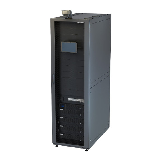
2 Overview Overview 2.1 Positioning To meet the requirements for customers' growing services, Huawei launches the FusionModule500 that can be rapidly deployed and flexibly expanded. The FusionModule500 is positioned as a small edge data center solution and occupies about 10 m . -
Page 25: Features
FusionModule500 Smart Mini Data Center User Manual (Philippines, FusionModule500- SU61A12S) 2 Overview (3) FusionModule800 (4) FusionModule500 Figure 2-2 Position of the FusionModule500 for governments (1) FusionModule5000 (2) FusionModule2000 (3) FusionModule800 (4) FusionModule500 2.2 Features High Integration The smart module integrates the cabinet system, power supply and distribution system, cooling system, management system, surge protection and grounding system, and integrated cabling system to provide a comprehensive solution. -
Page 26: Typical Application Scenarios And Configurations
FusionModule500 Smart Mini Data Center User Manual (Philippines, FusionModule500- SU61A12S) 2 Overview Powerful Monitoring ● Provides various sensors to monitor the functional modules. ● Provides a pad to easily manage the functional modules locally. 2.3 Typical Application Scenarios and Configurations 2.3.1 Typical Scenarios... - Page 27 FusionModule500 Smart Mini Data Center User Manual (Philippines, FusionModule500- SU61A12S) 2 Overview Item Specifications Power backup time 60–240 minutes Power distribution UPS2000-G, lithium battery, and rPDU Monitoring ECC800-Pro, temperature and humidity (T/H) sensor, smoke detector, water sensor, PAD, intelligent lock, WiFi converter, and NetEco...
-
Page 28: System Architecture
FusionModule500 Smart Mini Data Center User Manual (Philippines, FusionModule500- SU61A12S) 3 System Architecture System Architecture 3.1 Structural System The cabinet possesses the following features: ● The cabinet houses standard 19-inch wide devices. ● Two horizontal rPDUs are installed at the rear of the cabinet. -
Page 29: Power Supply And Distribution System
FusionModule500 Smart Mini Data Center User Manual (Philippines, FusionModule500- SU61A12S) 3 System Architecture 3.2 Power Supply and Distribution System 3.2.1 Overview The UPS supplies uninterruptible power to IT loads by means of lithium batteries when the external power supply fails. - Page 30 FusionModule500 Smart Mini Data Center User Manual (Philippines, FusionModule500- SU61A12S) 3 System Architecture (1) Liquid crystal display (2) Maintenance bypass (3) Optional card slot (LCD) (MBS) port (4) Battery management (5) RS232 (6) RS485 system (BMS) port communications ports communications port...
-
Page 31: Power Distribution Subrack
FusionModule500 Smart Mini Data Center User Manual (Philippines, FusionModule500- SU61A12S) 3 System Architecture Item Specifications Dimensions (H x W x 131 mm x 438 mm x 480 mm Weight 15 kg 3.2.3 Power Distribution Subrack Table 3-3 Technical specifications Item... -
Page 32: Rpdu
FusionModule500 Smart Mini Data Center User Manual (Philippines, FusionModule500- SU61A12S) 3 System Architecture Table 3-4 Lithium battery technical specifications Item Specifications Capacity 100 Ah Voltage 48 V DC Application scope 6 kVA UPS Dimensions (H x W x D) 130 mm x 442 mm x 396 mm (excluding... -
Page 33: Cooling System
FusionModule500 Smart Mini Data Center User Manual (Philippines, FusionModule500- SU61A12S) 3 System Architecture 3.3 Cooling System Figure 3-5 Integrated air conditioner 3.3.1 Application Conditions Operating Environment Table 3-6 Operating environment Item Integrated Air Conditioner Operating temperature 0–40°C Operating humidity 5%–95% RH (non-condensing) Storage temperature –40°C to +70°C (without refrigerant) -
Page 34: Technical Specifications
FusionModule500 Smart Mini Data Center User Manual (Philippines, FusionModule500- SU61A12S) 3 System Architecture Table 3-7 Derating coefficients Altitude 1000 1500 2000 2500 3000 3500 4000 0.887 0.835 0.785 0.737 0.692 0.649 0.608 volume coefficie Cooling 0.940 0.909 0.878 0.846 0.815 0.784... -
Page 35: System Functions
FusionModule500 Smart Mini Data Center User Manual (Philippines, FusionModule500- SU61A12S) 3 System Architecture The NetEco can manage the infrastructures of a single data center or of data centers in various areas in a centralized manner. The ECC800-Pro manages the real-time status, alarms, and configuration information about the devices inside the smart module. -
Page 36: App View
FusionModule500 Smart Mini Data Center User Manual (Philippines, FusionModule500- SU61A12S) 3 System Architecture Monitors and displays the compressor running status. 3.4.2.2 App View ● Generates a 2.5D layout view that matches the actual layout of the smart module, including the power distribution module, smart cooling product, and T/H sensor. -
Page 37: Key Hardware Devices
FusionModule500 Smart Mini Data Center User Manual (Philippines, FusionModule500- SU61A12S) 3 System Architecture ● Supports the aisle emergency ventilation linkage logic. The cabinet doors are opened by default under linkage. ● If the protected area of the fire extinguishing system is inside the smart module, when a smoke alarm is generated, the door of the linked cabinet does not open. - Page 38 FusionModule500 Smart Mini Data Center User Manual (Philippines, FusionModule500- SU61A12S) 3 System Architecture Item Specifications Weight 6.3 kg (with a single power module and a main control module) Color Black Installation requirements Can be installed in a 1 U space in a...
-
Page 39: Main Control Module
FusionModule500 Smart Mini Data Center User Manual (Philippines, FusionModule500- SU61A12S) 3 System Architecture 3.4.3.1.2 Main Control Module Figure 3-9 ECC800-Pro collector main control module (1) USB (2) Status indicator (3) AIDI_1 (4) AIDI_2 (5) COM1/AIDI_4 (6) COM3/12V (7) WAN1 (8) LAN1/POE... - Page 40 FusionModule500 Smart Mini Data Center User Manual (Philippines, FusionModule500- SU61A12S) 3 System Architecture Item Specifications Power output ● Output voltage: 42–58 V DC (rated voltage: 53.5 V DC) ● Output power of two power module supplies: 2000 W (200– 240 V AC); 940 W (linear derating at 85–175 V AC) ●...
- Page 41 FusionModule500 Smart Mini Data Center User Manual (Philippines, FusionModule500- SU61A12S) 3 System Architecture Item Specifications Wireless Supports wireless communication that complies with communicatio IEEE802.15.4. Supports the 4G module, SMS sending, and 3G communication, and provides a standard SIM card slot.
- Page 42 FusionModule500 Smart Mini Data Center User Manual (Philippines, FusionModule500- SU61A12S) 3 System Architecture Table 3-14 ECC800-Pro 4G parameters Item Specifications 3G/4G operation LTE (FDD): BAND1, BAND2, BAND3, BAND4, BAND5, frequency BAND7, BAND8, BAND20 DC-HSPA+/HSPA+/HSPA/UMTS: 850/900/1900/2100 GSM/GPRS/EDGE: 850/900/1800/1900 MHz 3G/4G EIRP (max.)
- Page 43 FusionModule500 Smart Mini Data Center User Manual (Philippines, FusionModule500- SU61A12S) 3 System Architecture Item Description Yellow ACT data communication, blinking indicator Table 3-16 COM1/AIDI_4, COM2/AIDI_5 port pin definitions Item Description Pin1 RS485+ sequence Pin2 RS485- Pin3 12V DC_OUT Pin4 RS485+...
- Page 44 FusionModule500 Smart Mini Data Center User Manual (Philippines, FusionModule500- SU61A12S) 3 System Architecture Table 3-18 COM4/CAN port pin definitions Item Description Pin1 RS485+ sequence Pin2 RS485- Pin3 Pin4 RS485+ Pin5 RS485- Pin6 Pin7 CAN_H Pin8 CAN_L The following provides the AIDI_1, AIDI_2 and AIDI_3 ports pin definitions.
- Page 45 FusionModule500 Smart Mini Data Center User Manual (Philippines, FusionModule500- SU61A12S) 3 System Architecture Table 3-20 DO/12V port pin definitions Item Description Pin1 sequence Pin2 Pin3 12V DC_OUT Pin4 Pin5 Pin6 DO_OUT+ Pin7 DO_OUT- Pin8 Indicator Green Power output indicator indicator ●...
- Page 46 FusionModule500 Smart Mini Data Center User Manual (Philippines, FusionModule500- SU61A12S) 3 System Architecture Indica Color Name Status Description Blinking at The software runs properly long (the indicator blinks at 0.5 intervals Hz, on for 1s and then off for 1s) or the ECC800-Pro registers with the NetEco successfully.
-
Page 47: Power Module
FusionModule500 Smart Mini Data Center User Manual (Philippines, FusionModule500- SU61A12S) 3 System Architecture Function Operation Description Indicator Status Description Press and hold down the button for The RF_Z indicator is more than 8s to clear network steady on. parameters. WLAN enabling... -
Page 48: Environment Monitoring System
FusionModule500 Smart Mini Data Center User Manual (Philippines, FusionModule500- SU61A12S) 3 System Architecture Indicator Color Name Status Description Hibernation The module generates no protection alarms. Blinking at The communication between long the module and the outside is intervals interrupted (the indicator blinks at 0.5 Hz, on for 1s and then... -
Page 49: T/H Sensor
FusionModule500 Smart Mini Data Center User Manual (Philippines, FusionModule500- SU61A12S) 3 System Architecture 3.4.3.2.2 T/H Sensor Figure 3-13 Appearance The T/H sensor uses an RJ45 connector. NO TE The appearance of the T/H sensor depends on the onsite delivery. Figure 3-14 Pins of an RJ45 connector... -
Page 50: Smoke Detector
FusionModule500 Smart Mini Data Center User Manual (Philippines, FusionModule500- SU61A12S) 3 System Architecture Item Specifications Humidity precision ±5% RH (25°C, 20%–80% RH) Operating temperature –20°C to +70°C Operating voltage 9–16 V DC Storage temperature –40°C to +70°C Output RS485 3.4.3.2.3 Smoke Detector A smoke detector detects smoke around cabinets. - Page 51 FusionModule500 Smart Mini Data Center User Manual (Philippines, FusionModule500- SU61A12S) 3 System Architecture Figure 3-16 Cabinet electronic clasp lock (1) LED indicator (2) DIP switch (3) RJ45 power port Table 3-29 RJ45 port definitions Pin Description Description RS485+ RS485+ RS485-...
-
Page 52: Pad
FusionModule500 Smart Mini Data Center User Manual (Philippines, FusionModule500- SU61A12S) 3 System Architecture Table 3-30 LED indicator status Indi Color Name Operat Status Description cato Green Module Blinki ● The door lock is paired running with the host, and the... - Page 53 FusionModule500 Smart Mini Data Center User Manual (Philippines, FusionModule500- SU61A12S) 3 System Architecture Figure 3-17 PAD Table 3-31 PAD structural specifications Item Specifications Dimensions (L x W x 243 mm x 164 mm x 7.8 mm Weight About 460 g...
-
Page 54: Wifi Module
FusionModule500 Smart Mini Data Center User Manual (Philippines, FusionModule500- SU61A12S) 3 System Architecture Item Specifications Camera ● Rear camera: 8-megapixel, F2.4 aperture, automatic focus ● Front camera: 2-megapixel, F2.4 aperture, fixed focus ● Sensor type: BSI ● Flash: not supported ●... -
Page 55: Optional) Camera
FusionModule500 Smart Mini Data Center User Manual (Philippines, FusionModule500- SU61A12S) 3 System Architecture Item Specifications Network ● 11n: up to 150 Mbps bandwidth ● 11g: up to 54 Mbps ● 11b: up to 11 Mbps Frequency band 2.4–2.4835 GHz Wireless... -
Page 56: Optional) Vcn510
FusionModule500 Smart Mini Data Center User Manual (Philippines, FusionModule500- SU61A12S) 3 System Architecture Table 3-34 C3220 camera technical specifications Item Specifications Image sensor 1/2.7'' two-megapixel progressive scan CMOS Minimum illumination ● Color: 0.002 lux (F1.2, AGC ON, 1/30s shutter speed) ●... -
Page 57: Optional) Neteco Intelligent Data Center Management System
FusionModule500 Smart Mini Data Center User Manual (Philippines, FusionModule500- SU61A12S) 3 System Architecture Item Specifications Ingress and egress bandwidth The ingress bandwidth does not exceed 128 Mbit/s. The egress bandwidth does not exceed 256 Mbit/s. Table 3-36 Hardware specifications Item... -
Page 58: Server
FusionModule500 Smart Mini Data Center User Manual (Philippines, FusionModule500- SU61A12S) 3 System Architecture The management system provides a GUI to implement comprehensive management functions based on requirements. The system mainly monitors following devices: ● Power equipment: smart cooling product, Power distribution module, UPS, and so on ●... -
Page 59: Lan Switch
FusionModule500 Smart Mini Data Center User Manual (Philippines, FusionModule500- SU61A12S) 3 System Architecture 3.4.4.3 LAN Switch Select LAN switches based on site requirements. Table 3-38 LAN switch Model Maximum Number of Ports S5331-H24P4XC Twenty-four 10/100/1000BASE-T Ethernet ports, four 10GE SFP+ ports... -
Page 60: Surge Protection And Grounding System
FusionModule500 Smart Mini Data Center User Manual (Philippines, FusionModule500- SU61A12S) 3 System Architecture Figure 3-22 Networking mode 3.5 Surge Protection and Grounding System 3.5.1 Surge Protection Solution The Smart Module is mainly used for building equipment rooms. Its power distribution system is a subsystem of the building power distribution system. Class I surge protective devices (SPDs) of the power system are provided by the general low-voltage power distribution room or cabinet of the building. -
Page 61: Cable Management
FusionModule500 Smart Mini Data Center User Manual (Philippines, FusionModule500- SU61A12S) 3 System Architecture that cannot be directly connected, such as cabinets and cabinet doors. A cable for connecting these two metal components has a minimum cross-sectional area of 6 mm ●... -
Page 62: Installation Guide
FusionModule500 Smart Mini Data Center User Manual (Philippines, FusionModule500- SU61A12S) 4 Installation Guide Installation Guide 4.1 Installation Preparations 4.1.1 Tools and Instruments Prepare the tools and meters required for installation. Table 4-1 General tools and instruments Name, Specifications, and Appearance... - Page 63 FusionModule500 Smart Mini Data Center User Manual (Philippines, FusionModule500- SU61A12S) 4 Installation Guide Name, Specifications, and Appearance Right angle Electrician's knife Impact tool Heat gun Needle-nose Diagonal pliers RJ11 crimping tool Polyvinyl pliers chloride (PVC) insulation tape Wire stripper Hydraulic pliers...
- Page 64 FusionModule500 Smart Mini Data Center User Manual (Philippines, FusionModule500- SU61A12S) 4 Installation Guide Table 4-2 Tools and instruments for installing smart cooling products Name, Specifications, and Appearance Flashlight Hacksaw Pallet truck Electric balance Antifreeze gloves Cutter Welding torch 5% silver solder...
-
Page 65: Installation Environment Check
FusionModule500 Smart Mini Data Center User Manual (Philippines, FusionModule500- SU61A12S) 4 Installation Guide Name, Specifications, and Appearance a. Pressure gauge and leather hose: dedicated for R410A. The measuring range of the pressure gauges must be at least 4.0 MPa, and the leather hoses must withstand a pressure of at least 4.5 MPa. - Page 66 Condensate drain outlet: Drains □ Passed □ Failed condensate water from the smart cooling product. Figure 4-1 Space requirements NO TE If any of the requirements is not met, contact Huawei technical support. Issue 02 (2021-06-30) Copyright © Huawei Technologies Co., Ltd.
-
Page 67: Site Equipment Preparation
FusionModule500 Smart Mini Data Center User Manual (Philippines, FusionModule500- SU61A12S) 4 Installation Guide 4.1.3 Site Equipment Preparation ● All cabinets and devices have been delivered to the site and checked against the delivery list. ● Cabinets and devices need to be transported to the specified positions based on the detailed equipment room layout diagram and unpacked for further installation. -
Page 68: Personnel Requirements
Only trained and qualified personnel who fully understand basic safety precautions are allowed to install and operate a modular data center. CA UTION Huawei will not be liable for any consequence caused by the violation of this document. The requirements are as follows: ●... -
Page 69: Cabinet Transportation And Unpacking
Check against the packing list that the equipment and fittings are correct and complete. If some fittings are missing or do not comply with the packing list, record the information and contact your local Huawei office immediately. After checking that the cabinet is intact, remove the screw assemblies that... -
Page 70: Optional) Removing The Aisle Containment
FusionModule500 Smart Mini Data Center User Manual (Philippines, FusionModule500- SU61A12S) 4 Installation Guide Figure 4-3 Removing an ordinary cabinet Remove the cabinet from the pallet and move the cabinet to the installation position. NO TICE To avoid personal injury, prevent the cabinet from falling over during transportation. - Page 71 FusionModule500 Smart Mini Data Center User Manual (Philippines, FusionModule500- SU61A12S) 4 Installation Guide Procedure Step 1 Open the front and rear doors of the cabinet. Step 2 (Optional) Cut off the cable tie on the PAD cable in the cabinet, and pull the cable into the cabinet through the front door.
- Page 72 FusionModule500 Smart Mini Data Center User Manual (Philippines, FusionModule500- SU61A12S) 4 Installation Guide Figure 4-5 Removing the gas springs NO TICE Remove the gas springs only when the door is open. Step 4 Disconnect the cabinet ground cable. Step 5 Lift the cabinet doors off the hinges. Remove the front and rear doors.
- Page 73 FusionModule500 Smart Mini Data Center User Manual (Philippines, FusionModule500- SU61A12S) 4 Installation Guide Figure 4-6 Removing the cabinet doors Step 6 Remove the top plate from the cabinet using a Phillips screwdriver. Figure 4-7 Removing the top plate Step 7 Remove the screws securing the aisle containment to the cabinet using a Phillips screwdriver, and remove the aisle containment from the cabinet.
-
Page 74: Installing A Cabinet
FusionModule500 Smart Mini Data Center User Manual (Philippines, FusionModule500- SU61A12S) 4 Installation Guide Figure 4-8 Removing an aisle containment Step 8 Move the removed glass doors, gas springs, top plate, aisle containment, and cabinet to the specified installation position using an elevator. - Page 75 FusionModule500 Smart Mini Data Center User Manual (Philippines, FusionModule500- SU61A12S) 4 Installation Guide Step 3 Level the cabinet using a wrench. NO TICE ● Use a measuring tape to check that the vertical distance between the top of the 2000 mm high cabinet and the floor is 2000 mm (+3 mm). Then use a level to check that the cabinet is level.
-
Page 76: Installing A Drainage Pipe For The Smart Cooling Product
FusionModule500 Smart Mini Data Center User Manual (Philippines, FusionModule500- SU61A12S) 4 Installation Guide 4.2.4 Installing a Drainage Pipe for the Smart Cooling Product Context The condensate drainpipe has been installed on the smart cooling product before delivery. You need to route the drainpipe from the bottom onsite. -
Page 77: Installing Power Supply And Distribution Devices
FusionModule500 Smart Mini Data Center User Manual (Philippines, FusionModule500- SU61A12S) 4 Installation Guide Figure 4-12 Drainpipe routed from the bottom NO TICE ● After routing the water pipe, secure it to the pipe assembly using cable ties, and seal the cable hole using firestop putty. -
Page 78: Optional) Installing Busbars
FusionModule500 Smart Mini Data Center User Manual (Philippines, FusionModule500- SU61A12S) 4 Installation Guide Figure 4-13 Installing a lithium battery NO TICE ● The lithium battery weighs about 43 kg. Check the load-bearing capability of the rack tray before installation. ● The lithium battery is 396 mm deep. Check the depth of the rack before installation. -
Page 79: Installing Rpdus
FusionModule500 Smart Mini Data Center User Manual (Philippines, FusionModule500- SU61A12S) 4 Installation Guide NO TE The busbar needs to be installed at the 17th–18th U position. Determine the busbar installation position based on the lithium battery configuration. Figure 4-14 Installing busbars ----End 4.2.5.3 Installing rPDUs... -
Page 80: Installing Monitoring Devices
FusionModule500 Smart Mini Data Center User Manual (Philippines, FusionModule500- SU61A12S) 4 Installation Guide Figure 4-15 Installing rPDUs ----End 4.2.6 Installing Monitoring Devices 4.2.6.1 Installing the SIM Card and Antenna If a subscriber identity module (SIM) card and an antenna are configured, perform the following steps to install them. -
Page 81: Installing A Pad
FusionModule500 Smart Mini Data Center User Manual (Philippines, FusionModule500- SU61A12S) 4 Installation Guide Figure 4-17 Installing a SIM card Step 3 Reconnect the signal cable to the panel of the ECC800-Pro main control module based on the recorded position. Step 4 Install the antenna. - Page 82 FusionModule500 Smart Mini Data Center User Manual (Philippines, FusionModule500- SU61A12S) 4 Installation Guide Figure 4-19 PAD installation position (1) PAD installation position Procedure Step 1 Adjust the width and height of the PAD support to match the dimensions of the PAD to be installed.
- Page 83 FusionModule500 Smart Mini Data Center User Manual (Philippines, FusionModule500- SU61A12S) 4 Installation Guide Figure 4-21 Removing the nut Step 3 Route the PAD power cable to the cable hole in the PAD support and connect the cable to the PAD.
-
Page 84: Installing Remote T/H Sensors For The Smart Cooling Product
Table 4-5 DIP switch settings on T/H sensors Address DIP Switch Sequence No. NO TICE The default address of T/H sensors purchased from Huawei is 1. Step 3 Insert the pre-routed cables into the ports on the T/H sensors on the front and rear doors. ----End 4.2.6.4 Installing T/H Sensors... -
Page 85: Installing An Electrode Water Sensor
Address DIP Switch Sequence No. NO TICE The default address of T/H sensors purchased from Huawei is 1. Step 3 Insert the pre-routed cable into the port on the T/H sensor on the front door. ----End 4.2.6.5 Installing an Electrode Water Sensor Procedure Step 1 Place the water sensor on the floor under the cabinet. -
Page 86: Optional) Installing A Server
FusionModule500 Smart Mini Data Center User Manual (Philippines, FusionModule500- SU61A12S) 4 Installation Guide Figure 4-23 Routing a signal cable ----End 4.2.6.6 (Optional) Installing a Server Procedure Step 1 Determine the installation position of the server and check whether floating nuts are installed. - Page 87 FusionModule500 Smart Mini Data Center User Manual (Philippines, FusionModule500- SU61A12S) 4 Installation Guide Figure 4-25 Installing guide rails Place a guide rail horizontally at the installation position in the cabinet. Tighten the screws to secure the guide rail. Repeat the preceding steps to install the other guide rail.
-
Page 88: Optional) Installing A Camera
FusionModule500 Smart Mini Data Center User Manual (Philippines, FusionModule500- SU61A12S) 4 Installation Guide Figure 4-27 Connecting the power cable Use a hook-and-loop fastener to secure the power cable. Figure 4-28 Securing the power cable Route the power cable along the cable tray neatly, use cable ties to bind the power cable, and use diagonal pliers to trim off the excess of the cable ties. - Page 89 FusionModule500 Smart Mini Data Center User Manual (Philippines, FusionModule500- SU61A12S) 4 Installation Guide Preparations Tool: Phillips screwdriver Materials: SD card, camera Procedure Step 1 (Optional) Install an SD card. Remove the transparent cover using a Phillips screwdriver. Figure 4-29 Removing the transparent cover Gently insert the SD card into the SD card slot.
- Page 90 FusionModule500 Smart Mini Data Center User Manual (Philippines, FusionModule500- SU61A12S) 4 Installation Guide Figure 4-31 Installing a camera base (1) Cable outlet Step 4 Install the mounting plate with the camera at the top of the front door of the end...
-
Page 91: Optional) Installing A Lan Switch
FusionModule500 Smart Mini Data Center User Manual (Philippines, FusionModule500- SU61A12S) 4 Installation Guide Figure 4-33 Adjusting the camera NO TICE ● By default, the camera is horizontally installed, and the surveillance video is displayed horizontally. During the installation, adjust the surveillance angle to avoid video image rotation after the installation. -
Page 92: Optional) Installing A Vcn510
FusionModule500 Smart Mini Data Center User Manual (Philippines, FusionModule500- SU61A12S) 4 Installation Guide NO TE This section describes only the installation method. The actual product appearance prevails. Figure 4-35 Installing a LAN switch Step 3 Connect the LAN switch power cable to the PDU2000. - Page 93 FusionModule500 Smart Mini Data Center User Manual (Philippines, FusionModule500- SU61A12S) 4 Installation Guide Figure 4-37 Removing screws Then loosen the three fastening screws (M3 x 5 grub screw, white) that are used to connect the subrack bottom to the front panel. Remove the subrack cover and front panel as shown in the lower-right figure.
- Page 94 FusionModule500 Smart Mini Data Center User Manual (Philippines, FusionModule500- SU61A12S) 4 Installation Guide Figure 4-39 Removing the upper cover of the chassis NO TE When removing the upper cover from the chassis, do not use one hand to perform this operation.
- Page 95 FusionModule500 Smart Mini Data Center User Manual (Philippines, FusionModule500- SU61A12S) 4 Installation Guide Figure 4-41 Installing the SATA cable and power cable (1) SATA cable (2) Power cable NO TE When the VCN510 is delivered, the SATA cable connecting to the hard disk is fixed using blue tapes.
- Page 96 FusionModule500 Smart Mini Data Center User Manual (Philippines, FusionModule500- SU61A12S) 4 Installation Guide Figure 4-43 Installing a hard disk Hold the disk with one hand. Use the other hand to turn over the device at a 90-degree angle. Fasten the preinstalled screws from the rear panel of the device.
- Page 97 FusionModule500 Smart Mini Data Center User Manual (Philippines, FusionModule500- SU61A12S) 4 Installation Guide Figure 4-45 Installing the floating nuts (1) Floating nuts NO TE The VCN510 is compact and lightweight. It can be directly fixed on the cabinet with M6 screws and mounting ears without using a guide rail.
-
Page 98: Cable Routing
FusionModule500 Smart Mini Data Center User Manual (Philippines, FusionModule500- SU61A12S) 4 Installation Guide Figure 4-47 Installing the device ----End 4.3 Cable Routing 4.3.1 System Cabling Rules Attaching Cable Labels NO TICE A cable label must be consistent with the corresponding cabinet number. - Page 99 FusionModule500 Smart Mini Data Center User Manual (Philippines, FusionModule500- SU61A12S) 4 Installation Guide Figure 4-48 Neatly organizing cables Keep a large number of cables neat and appealing in a cabinet by using cable organizers. Move the excess parts of cables in unnoticeable positions, as...
- Page 100 FusionModule500 Smart Mini Data Center User Manual (Philippines, FusionModule500- SU61A12S) 4 Installation Guide Cable Spacing Requirements Comply with the following requirements if possible to lay out different types of cables: Separate AC and DC power cables from diverse non-shielded signal cables.
- Page 101 FusionModule500 Smart Mini Data Center User Manual (Philippines, FusionModule500- SU61A12S) 4 Installation Guide Keep cables far away from heat sources such as radiators and heat vents. If unavoidable, take heat resistant measures. Keep cables far away from operating components such as fan blades and do not bind cables to an airflow path of fans.
-
Page 102: Cable Connections To The Power Supply And Distribution System
FusionModule500 Smart Mini Data Center User Manual (Philippines, FusionModule500- SU61A12S) 4 Installation Guide Ensure that the cable ties are wrapped and secured in the same direction and do not generate interference with subsequent operations, as shown in Figure 4-55. Figure 4-55 Direction for securing cable ties 4.3.2 Cable Connections to the Power Supply and Distribution... -
Page 103: Connecting Cabinet Input Power Cables
FusionModule500 Smart Mini Data Center User Manual (Philippines, FusionModule500- SU61A12S) 4 Installation Guide 4.3.2.2 Connecting Cabinet Input Power Cables Context The power distribution subrack position in the cable connection figure is for reference only. The actual position may vary. Procedure Step 1 (Optional) Connect input power cables to the PDU. -
Page 104: Connecting Cables Between The Lithium Battery And The Ups
FusionModule500 Smart Mini Data Center User Manual (Philippines, FusionModule500- SU61A12S) 4 Installation Guide Figure 4-58 Connecting rPDU terminal blocks NO TE The rPDU enclosure ground cable can be connected to the nearest round hole on the mounting bar and secured using screws. - Page 105 FusionModule500 Smart Mini Data Center User Manual (Philippines, FusionModule500- SU61A12S) 4 Installation Guide ● The actual number of batteries depends on the onsite configuration. Procedure Step 1 Connect power cables between lithium batteries and the UPS. Connect the positive battery terminal to the RTN+ port on the busbar and the negative battery terminal to the –48 V port on the busbar.
- Page 106 FusionModule500 Smart Mini Data Center User Manual (Philippines, FusionModule500- SU61A12S) 4 Installation Guide Figure 4-60 Connecting cables between the busbars, PDU, and UPS Step 2 Connect communications cables between lithium batteries and the UPS. After lithium batteries are connected in parallel, connect a signal cable to the BMS port of the UPS.
-
Page 107: Management System Cable Connection
FusionModule500 Smart Mini Data Center User Manual (Philippines, FusionModule500- SU61A12S) 4 Installation Guide Figure 4-61 Connecting communications cables between lithium batteries and the ----End 4.3.3 Management System Cable Connection 4.3.3.1 Connecting VCN Cables Prerequisites Cables have been prepared. Procedure Step 1 Connect one end of the ground cable to the ground terminal on the device and the other end to the ground point on the cabinet. -
Page 108: Verifying The Installation
FusionModule500 Smart Mini Data Center User Manual (Philippines, FusionModule500- SU61A12S) 4 Installation Guide Figure 4-62 Ports on the VCN (1) Ground terminal (2) GE1 port (3) GE2 port (4) Power button (5) Power port Step 3 Connect one end of the power cable to the input power port on the power module and the other end to the PDU2000 in the cabinet. - Page 109 FusionModule500 Smart Mini Data Center User Manual (Philippines, FusionModule500- SU61A12S) 4 Installation Guide Check That Check Result All components are properly installed and no □ Passed □ Failed component is left onsite. Block empty cable holes using plugs or lids.
- Page 110 FusionModule500 Smart Mini Data Center User Manual (Philippines, FusionModule500- SU61A12S) 4 Installation Guide Check That Check Result The smart cooling product input voltage is within □ Passed □ Failed the range of rated voltage ±10%, and the input frequency is within the range of rated frequency ±3 Hz.
-
Page 111: Power-On Commissioning
FusionModule500 Smart Mini Data Center User Manual (Philippines, FusionModule500- SU61A12S) 5 Power-On Commissioning Power-On Commissioning 5.1 Power-On Commissioning for the Power Supply and Distribution System Prerequisites The installation has been checked. NO TICE Configure an upstream protective device that meets the overload and short-circuit protection requirements for the cabinet. -
Page 112: Ups Power-On Commissioning
FusionModule500 Smart Mini Data Center User Manual (Philippines, FusionModule500- SU61A12S) 5 Power-On Commissioning NO TICE When switching on the circuit breakers, observe whether there is any abnormal phenomenon, such as sparks. ----End 5.1.1 UPS Power-On Commissioning Step 1 Switch on the external battery circuit breaker (if any). -
Page 113: Connecting The Lithium Battery Supply
FusionModule500 Smart Mini Data Center User Manual (Philippines, FusionModule500- SU61A12S) 5 Power-On Commissioning Battery Capacity Description ● Default value: 100 Ah ● Value range: 50–2400 Ah. The value increases by 50 Ah each time you press SELECT. Step 5 Press and hold ON/MUTE for more than 5s. Release the button when you hear a beep sound. -
Page 114: Power-On Commissioning For The Cooling System
FusionModule500 Smart Mini Data Center User Manual (Philippines, FusionModule500- SU61A12S) 5 Power-On Commissioning Step 2 When multiple ESMs connected in parallel are powered on, observe the RUN indicator on each ESM panel. Communication is normal if the indicator is steady on and is not established if it blinks fast. -
Page 115: Initial Configuration
FusionModule500 Smart Mini Data Center User Manual (Philippines, FusionModule500- SU61A12S) 5 Power-On Commissioning 5.2.2 Initial Configuration Prerequisites One end of the straight-through cable has been connected to the communications port on the FusionCol5000, and the other end has been connected to the COM port on the ECC800-Pro. -
Page 116: Commissioning Procedure
FusionModule500 Smart Mini Data Center User Manual (Philippines, FusionModule500- SU61A12S) 5 Power-On Commissioning On the Running Parameters tab page, set smart cooling product running parameters. NO TE On the Running Parameters tab page, you are advised to set Temperature setpoint to 23°C, Humidity setpoint to 50% RH, Control mode to Cold aisle average value... - Page 117 FusionModule500 Smart Mini Data Center User Manual (Philippines, FusionModule500- SU61A12S) 5 Power-On Commissioning To learn the mapping between the saturation pressure and the saturation temperature of the R410A refrigerant, see Table 5-2. Table 5-2 Mapping between the saturation pressure and the saturation...
-
Page 118: Management System Power-On Commissioning
FusionModule500 Smart Mini Data Center User Manual (Philippines, FusionModule500- SU61A12S) 5 Power-On Commissioning Procedure Step 1 Log in to the ECC800-Pro WebUI as user admin. Choose Monitoring > Cooling > FusionCol5000-A0031. The page for commissioning smart cooling products is displayed. - Page 119 FusionModule500 Smart Mini Data Center User Manual (Philippines, FusionModule500- SU61A12S) 5 Power-On Commissioning NO TICE ● In ECC800 V100R002C10 and earlier versions, the default IP address of port WAN_1 is 192.168.1.10. ● The WAN1 port IP address cannot be set to an IP address in any of the following network segments: 192.168.0.x, 192.168.245.x, 192.168.246.x and...
- Page 120 FusionModule500 Smart Mini Data Center User Manual (Philippines, FusionModule500- SU61A12S) 5 Power-On Commissioning Figure 5-3 Adding an address Enable file download and set the security level of the trusted site to low. Figure 5-4 Setting parameters NO TE When switching between different versions of the ECC800-Pro on your PC, you are advised to clear the historical Internet Explorer cache.
-
Page 121: Preparations And App Login
– After the first login, change the password in time to ensure account security and prevent unauthorized network attacks, such as data tampering. Huawei will not be liable for any security issues caused by your failure to change the preset password in time or password loss after changing. - Page 122 ● Huawei AppGallery installed on the PAD Log in to the Huawei AppGallery client, search for FusionModule, and tap Install. Huawei AppGallery is preinstalled on Huawei PAD by default. ● Huawei AppGallery not installed on the PAD...
- Page 123 FusionModule500 Smart Mini Data Center User Manual (Philippines, FusionModule500- SU61A12S) 5 Power-On Commissioning Method Procedure Installation Verification Method 2: Log in to 1. Log in to the ECC800- the ECC800-Pro Pro WebUI on a PC. WebUI on a PC and 2.
-
Page 124: Initial Startup Password Authentication
FusionModule500 Smart Mini Data Center User Manual (Philippines, FusionModule500- SU61A12S) 5 Power-On Commissioning NO TE – If you have set a password when enabling WiFi for the first time, you do not need to set the password again. – The WiFi function is disabled by default. If you need to enable the WiFi function, change the WiFi password to ensure connection security. - Page 125 – Huawei AppGallery installed on the PAD Log in to the Huawei AppGallery client, search for Service Expert, and tap Install. Huawei AppGallery is preinstalled on Huawei PAD by default. – Huawei AppGallery not installed on the PAD Issue 02 (2021-06-30) Copyright ©...
- Page 126 FusionModule500 Smart Mini Data Center User Manual (Philippines, FusionModule500- SU61A12S) 5 Power-On Commissioning Table 5-5 Operation methods for the scenario where Huawei AppGallery is not installed on the PAD Method Procedure Installation Verification Install the app 1. Log in to Huawei...
-
Page 127: Date And Time
FusionModule500 Smart Mini Data Center User Manual (Philippines, FusionModule500- SU61A12S) 5 Power-On Commissioning If the message displayed on the page is changed from "Initial startup password authentication" to "Activated", the startup password authentication is complete. NO TE – After the first login, change the password in time to ensure system access security. -
Page 128: Commissioning Sensors
FusionModule500 Smart Mini Data Center User Manual (Philippines, FusionModule500- SU61A12S) 5 Power-On Commissioning Procedure Step 1 Add a UPS2000G-L. Log in to the ECC800-Pro WebUI as an administrator. Add a UPS2000G-L. Table 5-6 Adding a UPS2000G-L Path Parameter Setting Choose Device Select UPS from the drop-down list box. -
Page 129: Commissioning A T/H Sensor
FusionModule500 Smart Mini Data Center User Manual (Philippines, FusionModule500- SU61A12S) 5 Power-On Commissioning Procedure Step 1 Set smoke detector parameters. Log in to the ECC800-Pro WebUI as an administrator. Choose System Settings > Signal Name Modify. The Batch Signal Configuration tab page is displayed. - Page 130 FusionModule500 Smart Mini Data Center User Manual (Philippines, FusionModule500- SU61A12S) 5 Power-On Commissioning Figure 5-6 DIP switch definitions for T/H sensors NO TE Numbers 1 and 2 indicate the DIP switch settings of T/H sensors. The DIP switch of the T/H sensor on the front door is set to 2, and that of the T/H sensor on the rear door is set to 1.
-
Page 131: Commissioning The Electrode Water Sensor
FusionModule500 Smart Mini Data Center User Manual (Philippines, FusionModule500- SU61A12S) 5 Power-On Commissioning – If the connection is abnormal, check whether the device is properly connected to the ECC800-Pro, whether the device and the ECC800-Pro are running properly, and whether the parameter settings are consistent with the device parameters. -
Page 132: Commissioning A Cabinet Electronic Clasp Lock
FusionModule500 Smart Mini Data Center User Manual (Philippines, FusionModule500- SU61A12S) 5 Power-On Commissioning Procedure Step 1 Set water sensor parameters. NO TE The following describes how to connect a water sensor to the AI/DI_2 port on the ECC800- Pro. Log in to the ECC800-Pro WebUI as an administrator. - Page 133 FusionModule500 Smart Mini Data Center User Manual (Philippines, FusionModule500- SU61A12S) 5 Power-On Commissioning Step 3 Set device addresses for cabinet electronic clasp locks. ● A cabinet electronic clasp lock is installed at the front and rear doors of the cabinet respectively. The address for the cabinet electronic clasp lock on the front door is an odd number, and that for the cabinet electronic clasp lock on the rear door is an even number.
- Page 134 FusionModule500 Smart Mini Data Center User Manual (Philippines, FusionModule500- SU61A12S) 5 Power-On Commissioning Path Parameter Setting Communicat COM2 ions Port Device Enter the actual device address of Address the cabinet electronic clasp lock. Click Test Connect to check whether the connection between the cabinet electronic clasp lock and the ECC800-Pro is normal.
- Page 135 FusionModule500 Smart Mini Data Center User Manual (Philippines, FusionModule500- SU61A12S) 5 Power-On Commissioning Function Path Operation Open Choose Monitoring > Cabinet Select Open front door or Open cabinet and click the Controls tab. back door from the Open the electroni...
-
Page 136: Configuring Event Notification
FusionModule500 Smart Mini Data Center User Manual (Philippines, FusionModule500- SU61A12S) 5 Power-On Commissioning Figure 5-10 Removing the fastener NO TICE If the door still cannot be opened or closed properly, check the following items: ● Whether cables are connected correctly ●... - Page 137 FusionModule500 Smart Mini Data Center User Manual (Philippines, FusionModule500- SU61A12S) 5 Power-On Commissioning NO TE The DNS server address is provided by the local network operator. Click Test to check the email sending. If an email fails to be sent, check the outbox settings and DNS Server Address.
- Page 138 FusionModule500 Smart Mini Data Center User Manual (Philippines, FusionModule500- SU61A12S) 5 Power-On Commissioning Email Email Mailbox Server Encryption Remarks Type Server IP Address Mode and Domain SMTP port Name area, and 163 Mail smtp. Non- ensure that press Enter 163.com encryption: 25;...
- Page 139 FusionModule500 Smart Mini Data Center User Manual (Philippines, FusionModule500- SU61A12S) 5 Power-On Commissioning Figure 5-12 Adding an email address to receive emails NO TE Click Test to check whether the added mailbox is available. If it is available, Successfully to send the test email.
- Page 140 FusionModule500 Smart Mini Data Center User Manual (Philippines, FusionModule500- SU61A12S) 5 Power-On Commissioning Figure 5-13 Adding a mobile number NO TE Click Test to check whether the added mobile phone number is available. If it is available, Successfully to send the test short message. is displayed. If it is unavailable, Failed to send the test short message.
- Page 141 If the email address fails to be set, rectify the fault based on the handling suggestions of the error codes listed in the following table. If an error code is not listed in the following table, provide the ECC run log and contact Huawei technical support.
- Page 142 FusionModule500 Smart Mini Data Center User Manual (Philippines, FusionModule500- SU61A12S) 5 Power-On Commissioning Table 5-16 Mailbox error codes Type Error Code Suggestion Failed to 1. Check whether the IP address of the DNS resolve the server is correct. domain 2. Check whether the domain name of the name.
- Page 143 FusionModule500 Smart Mini Data Center User Manual (Philippines, FusionModule500- SU61A12S) 5 Power-On Commissioning Type Error Code Suggestion Check the firewall and router configurations between the ECC and the email server to ensure that the ECC communicates with the email server properly.
-
Page 144: Linkage Control
FusionModule500 Smart Mini Data Center User Manual (Philippines, FusionModule500- SU61A12S) 5 Power-On Commissioning Type Error Code Suggestion Provide ECC run logs and contact the service center to reduce the email sending frequency. Log in to the sender's mailbox client and enable the access to the insecure applications. -
Page 145: Unlocking The Cabinet Electronic Clasp Lock When A Smoke Alarm Is Generated
FusionModule500 Smart Mini Data Center User Manual (Philippines, FusionModule500- SU61A12S) 5 Power-On Commissioning Linkage Default Function Category Status Link smoke When this linkage status is set to on: alarm with ● If a smoke alarm is generated, the rear cabinet clasp lock door is opened. -
Page 146: Unlocking The Cabinet Electronic Clasp Lock When A Fire Alarm Is Generated
FusionModule500 Smart Mini Data Center User Manual (Philippines, FusionModule500- SU61A12S) 5 Power-On Commissioning NO TE Select Link smoke alarm with clasp lock open under Linkage Group. If its value is on, the corresponding logic configurations under Linkage Logic List are available. If its value is off, the corresponding logic configurations under Linkage Logic List are unavailable. -
Page 147: Link Emergency Ventilation With Clasp Lock Open
FusionModule500 Smart Mini Data Center User Manual (Philippines, FusionModule500- SU61A12S) 5 Power-On Commissioning Step 5 Modify the AI/DI_3 signal name. Log in to the ECC800-Pro WebUI as an administrator. Choose System Settings > Signal Name Modify. The Batch Signal Configuration tab page is displayed. -
Page 148: Optional) Neteco Management
FusionModule500 Smart Mini Data Center User Manual (Philippines, FusionModule500- SU61A12S) 5 Power-On Commissioning Follow-up Procedure After the alarm is cleared, you need to manually close the door. After the door is closed, the door open alarm is cleared. 5.3.11 (Optional) NetEco Management 5.3.11.1 Data Center Management... -
Page 149: Powering On A Server
FusionModule500 Smart Mini Data Center User Manual (Philippines, FusionModule500- SU61A12S) 5 Power-On Commissioning Step 3 Click Submit. Step 4 Set NetEco communications parameters and authentication password on the ECC800-Pro WebUI. Table 5-19 NetEco parameters Path Parameter Default Setting Value System Server IP 192.168.8. -
Page 150: Logging In To The Neteco Client
FusionModule500 Smart Mini Data Center User Manual (Philippines, FusionModule500- SU61A12S) 5 Power-On Commissioning Procedure Step 1 Check that the power cables and ground cables of the upstream components of the server are securely connected with correct polarity and in good contact. -
Page 151: Loading The Neteco Software License
Huawei will not be liable for any security issues caused by your failure to change the preset password in time or password loss after changing. -
Page 152: Installing Ne Adapters
FusionModule500 Smart Mini Data Center User Manual (Philippines, FusionModule500- SU61A12S) 5 Power-On Commissioning 5.3.11.1.6 Installing NE Adapters Install the NE adapters on the NetEco. Prerequisites You have obtained the adapter software installation packages. Procedure Choose Device Management > Configuration > Device Integration. -
Page 153: Example: Adding A Smart Module
FusionModule500 Smart Mini Data Center User Manual (Philippines, FusionModule500- SU61A12S) 5 Power-On Commissioning NO TE You can adjust the shape of Room, Room–ShapeNode, Building–ShapeNode, Floor– ShapeNode, Container–ShapeNode, and NetecoSite by: 1. Hold down Shift and click the frame to add a yellow dot. - Page 154 FusionModule500 Smart Mini Data Center User Manual (Philippines, FusionModule500- SU61A12S) 5 Power-On Commissioning Figure 5-19 Adding the smart module in the room area Step 6 Modify Management Info of the smart module as required or retain the default values. Step 7 Click on the toolbar to save the settings.
- Page 155 FusionModule500 Smart Mini Data Center User Manual (Philippines, FusionModule500- SU61A12S) 5 Power-On Commissioning Related Procedure Operatio Delete You can delete one module or multiple modules in batches on the modules current page. NOTE If a module contains subdevices, you cannot delete it. You can delete the module only after you delete subdevices in the module.
-
Page 156: Creating An Ecc800-Pro On The Neteco
FusionModule500 Smart Mini Data Center User Manual (Philippines, FusionModule500- SU61A12S) 5 Power-On Commissioning 5.3.11.1.9 Creating an ECC800-Pro on the NetEco Prerequisites ● You have logged in to the NetEco client by web browser. ● You have created modules in Data Center Planning. -
Page 157: Routine Maintenance
FusionModule500 Smart Mini Data Center User Manual (Philippines, FusionModule500- SU61A12S) 6 O&M O&M 6.1 Routine Maintenance 6.1.1 Monthly Maintenance Table 6-1 Monthly preventive maintenance table Maintenance Maintenance Operation Expected Result Troubleshootin Area Item Power supply and Operating status Check the surge ●... - Page 158 FusionModule500 Smart Mini Data Center User Manual (Philippines, FusionModule500- SU61A12S) 6 O&M Maintenance Maintenance Operation Expected Result Troubleshootin Area Item Operating ● Ambient ● If the environment temperature: temperature 0–40°C or humidity is abnormal, ● Humidity: check the 0%–95% RH...
- Page 159 FusionModule500 Smart Mini Data Center User Manual (Philippines, FusionModule500- SU61A12S) 6 O&M Maintenance Maintenance Operation Expected Result Troubleshootin Area Item Battery 1. The surface is If the battery appearance clean and tidy appearance is without abnormal, stains. contact Huawei technical 2.
- Page 160 FusionModule500 Smart Mini Data Center User Manual (Philippines, FusionModule500- SU61A12S) 6 O&M Maintenance Maintenance Operation Expected Result Troubleshootin Area Item Indicator The indicator on Check the the power output voltage module is steady and determine green. whether the power module is faulty.
- Page 161 FusionModule500 Smart Mini Data Center User Manual (Philippines, FusionModule500- SU61A12S) 6 O&M Maintenance Maintenance Operation Expected Result Troubleshootin Area Item Monitor interface Export smart If an alarm is (network cooling product generated, management logs, alarms, handle the system or WebUI)
- Page 162 FusionModule500 Smart Mini Data Center User Manual (Philippines, FusionModule500- SU61A12S) 6 O&M Maintenance Maintenance Operation Expected Result Troubleshootin Area Item Intelligent lithium Battery No battery Identify the battery management management cause of an monitoring system alarm alarm is alarm based on generated.
-
Page 163: Quarterly Maintenance
FusionModule500 Smart Mini Data Center User Manual (Philippines, FusionModule500- SU61A12S) 6 O&M 6.1.2 Quarterly Maintenance Table 6-2 Quarterly preventive maintenance table Maintenance Maintenance Operation Expected Result Troubleshootin Area Item Power supply and Operating status Check the surge ● The surge ●... - Page 164 FusionModule500 Smart Mini Data Center User Manual (Philippines, FusionModule500- SU61A12S) 6 O&M Maintenance Maintenance Operation Expected Result Troubleshootin Area Item Cleanliness Wipe the cabinet Remove the surface using a dust, especially white paper and from the air the paper does filter on the not turn black.
- Page 165 FusionModule500 Smart Mini Data Center User Manual (Philippines, FusionModule500- SU61A12S) 6 O&M Maintenance Maintenance Operation Expected Result Troubleshootin Area Item Battery 1. The surface is If the battery appearance clean and tidy appearance is without abnormal, stains. contact Huawei technical 2.
- Page 166 FusionModule500 Smart Mini Data Center User Manual (Philippines, FusionModule500- SU61A12S) 6 O&M Maintenance Maintenance Operation Expected Result Troubleshootin Area Item Battery bolts The location of Take photos the signs marked from multiple on battery angles and terminal bolts contact Huawei...
- Page 167 FusionModule500 Smart Mini Data Center User Manual (Philippines, FusionModule500- SU61A12S) 6 O&M Maintenance Maintenance Operation Expected Result Troubleshootin Area Item Shallow discharge Conduct a 1. Locate the test shallow cause when (recommended) discharge test an exception when the UPS is is identified.
- Page 168 FusionModule500 Smart Mini Data Center User Manual (Philippines, FusionModule500- SU61A12S) 6 O&M Maintenance Maintenance Operation Expected Result Troubleshootin Area Item Monitoring The monitoring If the indicator module indicator module indicator is off or any is steady green abnormal or blinking condition green.
- Page 169 FusionModule500 Smart Mini Data Center User Manual (Philippines, FusionModule500- SU61A12S) 6 O&M Maintenance Maintenance Operation Expected Result Troubleshootin Area Item Camera Camera On the ECC800- The monitoring If the availability Pro WebUI, page is properly monitoring choose displayed after page is not Maintenance >...
-
Page 170: Yearly Maintenance
FusionModule500 Smart Mini Data Center User Manual (Philippines, FusionModule500- SU61A12S) 6 O&M Maintenance Maintenance Operation Expected Result Troubleshootin Area Item Water sensor and Functions of the Place the water A water leakage If a water water detection water sensor and... - Page 171 FusionModule500 Smart Mini Data Center User Manual (Philippines, FusionModule500- SU61A12S) 6 O&M Maintenance Maintenance Operation Expected Result Troubleshootin Area Item Circuit breaker Switch on or off The circuit If the circuit the circuit breaker is breaker cannot breaker after switched on and...
- Page 172 FusionModule500 Smart Mini Data Center User Manual (Philippines, FusionModule500- SU61A12S) 6 O&M Maintenance Maintenance Operation Expected Result Troubleshootin Area Item Operating ● Ambient ● If the environment temperature: temperature 0–40°C or humidity is abnormal, ● Humidity: check the 0%–95% RH...
- Page 173 FusionModule500 Smart Mini Data Center User Manual (Philippines, FusionModule500- SU61A12S) 6 O&M Maintenance Maintenance Operation Expected Result Troubleshootin Area Item Power cables and The insulation ● Replace terminals layer of cables is damaged (between the UPS intact and cables. and the power terminals are ●...
- Page 174 FusionModule500 Smart Mini Data Center User Manual (Philippines, FusionModule500- SU61A12S) 6 O&M Maintenance Maintenance Operation Expected Result Troubleshootin Area Item Battery Check that the Set parameters management settings of correctly. parameter settings battery management parameters meet the requirements in the user manual.
- Page 175 FusionModule500 Smart Mini Data Center User Manual (Philippines, FusionModule500- SU61A12S) 6 O&M Maintenance Maintenance Operation Expected Result Troubleshootin Area Item Battery voltage ● Equalized 1. Check charging whether the voltage: 53.5 equalized V DC charging voltage and ● Float float...
- Page 176 FusionModule500 Smart Mini Data Center User Manual (Philippines, FusionModule500- SU61A12S) 6 O&M Maintenance Maintenance Operation Expected Result Troubleshootin Area Item Capacity test When the UPS is 1. Locate the (recommended) backed up, cause when discharge a an exception battery to the is identified.
- Page 177 FusionModule500 Smart Mini Data Center User Manual (Philippines, FusionModule500- SU61A12S) 6 O&M Maintenance Maintenance Operation Expected Result Troubleshootin Area Item ECC800-Pro AC input Input voltage: If the input 200–240 V AC voltage is abnormal, check Frequency: 45– the power grid...
- Page 178 FusionModule500 Smart Mini Data Center User Manual (Philippines, FusionModule500- SU61A12S) 6 O&M Maintenance Maintenance Operation Expected Result Troubleshootin Area Item Network interface The green If the indicator indicator indicator is status is steady on, and abnormal, check the yellow the network...
- Page 179 FusionModule500 Smart Mini Data Center User Manual (Philippines, FusionModule500- SU61A12S) 6 O&M Maintenance Maintenance Operation Expected Result Troubleshootin Area Item Camera Camera On the ECC800- The monitoring If the availability Pro WebUI, page is properly monitoring choose displayed after page is not Maintenance >...
-
Page 180: Troubleshooting
UPS again. Otherwise, the fault may be extended, or the UPS may be damaged. ● If the fault is not rectified, contact Huawei technical support. Table 6-4 Power supply and distribution system troubleshooting... - Page 181 FusionModule500 Smart Mini Data Center User Manual (Philippines, FusionModule500- SU61A12S) 6 O&M Symptom Possible Cause Measure The surge protection ● The SPD circuit ● Check that the SPD function fails. breaker is OFF. circuit breaker is turned on. The power ●...
- Page 182 FusionModule500 Smart Mini Data Center User Manual (Philippines, FusionModule500- SU61A12S) 6 O&M Symptom Possible Cause Measure The UPS does not start is not pressed long Press for more than after you press enough. 5 seconds until you hear a beep sound.
-
Page 183: Management System Troubleshooting
FusionModule500 Smart Mini Data Center User Manual (Philippines, FusionModule500- SU61A12S) 6 O&M Symptom Possible Cause Measure The user forgot the None ● If the user forgot only password. the LCD password (the preset password is 000001), use the feature code (the... - Page 184 FusionModule500 Smart Mini Data Center User Manual (Philippines, FusionModule500- SU61A12S) 6 O&M Symptom Possible Cause Measure The Alarm indicator Output overvoltage ● If a single PSU is (red) is steady on. protection locked out, disconnect the AC input from the...
-
Page 185: Alarm References
FusionModule500 Smart Mini Data Center User Manual (Philippines, FusionModule500- SU61A12S) 6 O&M Symptom Possible Cause Measure The ALM indicator Faults and alarms are View active alarms on (red) is steady on. generated. the WebUI and clear them one by one. - Page 186 FusionModule500 Smart Mini Data Center User Manual (Philippines, FusionModule500- SU61A12S) 6 O&M Component Alarm Name Alarm Possible Cause Measures Severit Inverter fault Critical The inverter output Eliminate the short short-circuits. circuit at the output port cable connection, and then power on and start the inverter again.
-
Page 187: Parts Replacement
FusionModule500 Smart Mini Data Center User Manual (Philippines, FusionModule500- SU61A12S) 6 O&M Component Alarm Name Alarm Possible Cause Measures Severit Single Batt. Critical ● The battery shell is ● Check whether the Exception broken, resulting in appearances of electrolyte and abnormal batteries electricity leakage. -
Page 188: Replacing A Gas Spring
FusionModule500 Smart Mini Data Center User Manual (Philippines, FusionModule500- SU61A12S) 6 O&M Figure 6-1 Removing a cabinet electronic clasp lock Step 4 Install the new cabinet electronic clasp lock at the front or rear door of a cabinet. NO TE ●... -
Page 189: Replacing A Pdu2000
FusionModule500 Smart Mini Data Center User Manual (Philippines, FusionModule500- SU61A12S) 6 O&M Procedure Step 1 Open the front or rear door of the cabinet. Step 2 Remove the nuts from the gas spring using an adjustable wrench. Step 3 Remove the gas springs. -
Page 190: Replacing Power Supply And Distribution System Components
FusionModule500 Smart Mini Data Center User Manual (Philippines, FusionModule500- SU61A12S) 6 O&M Procedure Step 1 Open the rear door of the cabinet. Step 2 Switch off the output circuit breaker of the power distribution subrack for the PDU2000. Disconnect the power cables and signal cables from the PDU2000 terminal block. - Page 191 FusionModule500 Smart Mini Data Center User Manual (Philippines, FusionModule500- SU61A12S) 6 O&M Step 2 Remove the protective panel from the SPD. Figure 6-3 Removing the protective panel Step 3 Measure the L1, L2, L3, and N voltages to PE using an electroprobe, as shown in...
-
Page 192: Replacing A Ups2000-G
FusionModule500 Smart Mini Data Center User Manual (Philippines, FusionModule500- SU61A12S) 6 O&M Figure 6-5 Replacing a surge protection module Step 5 Install the new surge protection module. Step 6 Reinstall the protective panel for the SPD, and switch the SPD circuit breaker to Step 7 Check whether there are alarms on the ECC800-Pro. -
Page 193: Replacing A Lithium Battery
FusionModule500 Smart Mini Data Center User Manual (Philippines, FusionModule500- SU61A12S) 6 O&M Step 4 Remove screws from the UPS front panel, and pull out the UPS. Step 5 Install the new UPS and screw it to the cabinet. Step 6 Connect the output power cables, signal cable, and UPS input power cables in sequence. -
Page 194: Replacing Management System Components
FusionModule500 Smart Mini Data Center User Manual (Philippines, FusionModule500- SU61A12S) 6 O&M Step 9 Hold down the Manual ON/OFF button for 15s for the battery to exit the maintenance mode. The battery is automatically activated and connects to the power system. - Page 195 FusionModule500 Smart Mini Data Center User Manual (Philippines, FusionModule500- SU61A12S) 6 O&M Step 3 Remove cables, USB flash drive, USB-to-WiFi module, and antennas from the ECC800-Pro main control module. Step 4 Loosen the screws on both sides of the ECC800-Pro main control module and pull the handles on both sides of the ECC800-Pro main control module to remove the main control module.
-
Page 196: Replacing An Ecc800-Pro Psu
FusionModule500 Smart Mini Data Center User Manual (Philippines, FusionModule500- SU61A12S) 6 O&M 6.4.3.2 Replacing an ECC800-Pro PSU Prerequisites D ANGER Do not touch the terminals in the rear of a removed PSU to avoid electric shocks. ● Tool: insulation gloves ●... -
Page 197: Replacing A Sim Card
FusionModule500 Smart Mini Data Center User Manual (Philippines, FusionModule500- SU61A12S) 6 O&M Procedure Step 1 Remove the 4G antenna cables and RF_Z antenna cables connected to the ports on the ECC800-Pro, as shown in Figure 6-9. Figure 6-9 Removing antennas Step 2 Install the spare 4G antenna cables and RF_Z antenna cables in the original positions and connect them to the ECC800-Pro. -
Page 198: Replacing A Camera
FusionModule500 Smart Mini Data Center User Manual (Philippines, FusionModule500- SU61A12S) 6 O&M Step 4 Remove the SIM card from the card slot. Figure 6-11 Removing a SIM card Step 5 Insert the spare SIM card into the card slot. Figure 6-12 Installing a SIM card Step 6 Install the ECC800-Pro main control module in the card slot. - Page 199 FusionModule500 Smart Mini Data Center User Manual (Philippines, FusionModule500- SU61A12S) 6 O&M Figure 6-13 Removing the transparent cover Step 2 Remove the SD card. Figure 6-14 Removing an SD card Step 3 Remove the monitoring network cable from the camera and remove the camera.
-
Page 200: Replacing A Vcn510
FusionModule500 Smart Mini Data Center User Manual (Philippines, FusionModule500- SU61A12S) 6 O&M Figure 6-15 Removing the camera Step 4 Install the new camera and SD card, reconnect the network cable, and secure the camera to the base using screws. Step 5 Commission the camera by referring to the ECC800-Pro user manual of the appropriate version. -
Page 201: Replacing A T/H Sensor (33010516)
FusionModule500 Smart Mini Data Center User Manual (Philippines, FusionModule500- SU61A12S) 6 O&M Procedure Step 1 Turn off the power switch of the VCN510, disconnect the power supply of the VCN510, remove the cables from the VCN510, label the cables, and record the original connection positions of the cables. -
Page 202: Replacing A Smoke Detector
FusionModule500 Smart Mini Data Center User Manual (Philippines, FusionModule500- SU61A12S) 6 O&M Procedure Step 1 Tap Shutdown on the controller home screen. NO TICE Exercise caution because the device is still energized after it is shut down on the controller home screen. -
Page 203: Replacing An Electrode Water Sensor
FusionModule500 Smart Mini Data Center User Manual (Philippines, FusionModule500- SU61A12S) 6 O&M Figure 6-17 Detector position (1) Smoke detector Procedure Step 1 Remove the smoke detector from the base. Step 2 Remove the cables from the smoke detector and apply insulation measures such as wrapping the cables with insulation tape to avoid hazards. - Page 204 FusionModule500 Smart Mini Data Center User Manual (Philippines, FusionModule500- SU61A12S) 6 O&M Procedure Step 1 Disconnect the cable between the water sensor and the ECC800-Pro. Step 2 Remove the faulty water sensor. Step 3 Place the new water sensor in the correct position.
-
Page 205: Technical Specifications
FusionModule500 Smart Mini Data Center User Manual (Philippines, FusionModule500- SU61A12S) 7 Technical Specifications Technical Specifications Table 7-1 Key technical specifications Item Specifications Module dimensions (H x W x D) Fully enclosed indoor cabinet: 2000 x (mm) 600 x 1350 Number of cabinets... -
Page 206: A Equipment Derating Coefficients
FusionModule500 Smart Mini Data Center User Manual (Philippines, FusionModule500- SU61A12S) A Equipment Derating Coefficients Equipment Derating Coefficients NO TE The coefficients listed in the Table A-1 are based on the dry air density being 1.225 kg/m (sea level +15ºC). Table A-1 Derating coefficients of the UPS2000-G... -
Page 207: B Acronyms And Abbreviations
FusionModule500 Smart Mini Data Center User Manual (Philippines, FusionModule500- SU61A12S) B Acronyms and Abbreviations Acronyms and Abbreviations alternate current Auto Transformer Switch ATSE Auto Transformer Switch Equipment Battery Interface Module Communication Interface Module direct current International Electrotechnical Commission miniature circuit breaker... - Page 208 FusionModule500 Smart Mini Data Center User Manual (Philippines, FusionModule500- SU61A12S) B Acronyms and Abbreviations uninterruptible power system Issue 02 (2021-06-30) Copyright © Huawei Technologies Co., Ltd.