Toshiba Infinia 7130 Series Maintenance Manual
Hide thumbs
Also See for Infinia 7130 Series:
- Resource manual (56 pages) ,
- Specification sheet (4 pages)
Table of Contents
Advertisement
Quick Links
Advertisement
Chapters
Table of Contents

Related Manuals for Toshiba Infinia 7130 Series


Summary of Contents for Toshiba Infinia 7130 Series
- Page 1 Infinia 7130, 7160, 7161, 7200, 7201, and 7220 Series DBM-2970287-C00...
- Page 2 Chapter 1 Hardware Overview Infinia™ Series Maintenance Manual ------------------------------------------------------------- 1-1...
- Page 3 Infinia™ Series Maintenance Manual ------------------------------------------------------------- 1-2...
-
Page 4: Table Of Contents
Contents 1.1. System Features.....................1-1 1.2. System Configuration .....................1-4 1.3. Infinia™ Field Replaceable Units (FRUs) ..............1-5 1.3.1. System Board ....................1-6 1.3.2. Microprocessor...................1-8 1.3.3. Single Inline Memory Modules (SIMMs) .............1-9 1.3.4. Power Supply ....................1-10 1.3.5. Floppy Disk Drive (FDD) .................1-11 1.3.6. Enhanced IDE Hard Disk Drive ..............1-13 1.3.7. - Page 5 Figures (Continued) Figure 1-14 Infinia™ Modem..................1-24 Figure 1-15 LED Module....................1-25 Figure 1-16 LCD Module....................1-25 ™ Figure 1-17 InTouch Module Remote Control ..............1-26 Figure 1-18 TV Tuner Card....................1-27 Figure 1-19 Monitor.......................1-29 Figure 1-20 Real-Time Clock Battery ................1-33 Tables Table 1-1 System Board Environmental Specifications ...........1-6 Table 1-2 Power Supply Specifications .
- Page 6 Tables (Continued) Table 1-24 Monitor Specifications .................1-29 Table 1-25 15- and 17-inch Monitor Factory Preset Resolution and Sync. Polarities ..1-31 Table 1-26 15-inch Monitor Power Management ............1-32 Table 1-27 17-inch Monitor Power Management ............1-32 Infinia™ Series Maintenance Manual ------------------------------------------------------------- 1-v...
- Page 7 Infinia™ Series Maintenance Manual ------------------------------------------------------------ 1-vi...
-
Page 8: System Features
System Features The Infinia™ Models 7130, 7160, 7161, 7200, 7201, and 7220 are some of the most powerful multimedia desktop computers available. Integrating advanced technologies and high-speed, energy-efficient components with a simple and elegant design, the Infinia™ line offers state- of-the-art capabilities in an easy-to-service package. - Page 9 DVD-ROM Infinia™ Model 7220 comes equipped with one SD-M1002 DVD-ROM and an MPEG2/AC-3 decoder board. ™ InTouch Module ™ The InTouch Module provides centralized control of various attached devices such as a television, FM radio, music CD player, and telephone answering ™...
- Page 10 External interfaces • Two serial 16550 UART compatible ports, one DB-9 serial port on the system board • One parallel port • One external SVGA Monitor connector • One keyboard port • Two Universal Serial Bus (USB) ports • One external mono microphone jack •...
-
Page 11: System Configuration
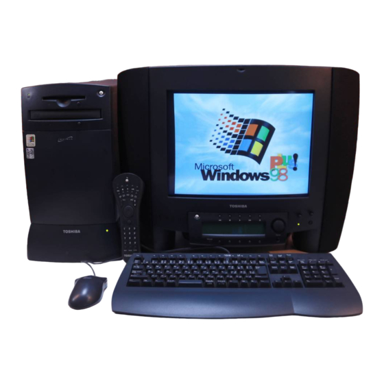
System Configuration The Infinia™ Personal Computer is shown in Figure 1-1 and its system configuration is illustrated in Figure 1-2. Figure 1-1 Infinia™ Personal Computer Figure 1-2 Infinia™ System Unit Configuration Infinia™ Series Maintenance Manual ------------------------------------------------------------- 1-4... -
Page 12: Infinia™ Field Replaceable Units (Frus)
Infinia™ Field Replaceable Units (FRUs) Each Infinia™ computer consists of the following FRU's. System board Microprocessor Single Inline Memory Modules (SIMMs) Power Supply 3.5" Floppy Disk Drive (FDD) 3.5" Enhanced IDE Hard Disk Drive (HDD) CD-ROM Drive (Models 7130, 7160, 7161, 7200, and 7201) DVD-ROM Drive and MPEG2/AC-3 Card (Model 7220 only) Keyboard Mouse... -
Page 13: System Board
System Board The Infinia™ system board has the following features. ® Intel Pentium microprocessor running at 133 MHz (Model 7130), 166 MHz ™ (Model 7160), 166 MHz MMX (Model 7161), 200 MHz (Model 7200), or ™ 200 MHz MMX (Model 7201 and 7220) ATX form factor system board Support for up to 128 MB of DRAM. -
Page 14: Figure 1-3 System Board Layout
Table 1-1 System Board Environmental Specifications (2/2) Item Specification Shock − Unpackaged 50G Trapezoidal waveform. Velocity change 170 in/sec − Packaged Product Free fall (in.) Velocity (in/sec) (Weight) <20 lbs 21-40 lbs 41-80 lbs 81-100 lbs Figure 1-3 System Board Layout Yamaha OPL4-ML wavetable Intel 82439HX Xcellerated (Model 7161, 7200, 7201, and 7220) -
Page 15: Microprocessor
Microprocessor ® Each Infinia™ computer comes with a 3.3 volt Intel Pentium Processor running at 133 MHz ™ (Model 7130), 166 MHz (Model 7160), 166 MHz MMX (Model 7161), 200 MHz (Model ™ 7200), or 200 MHz MMX (Models 7201and 7220). The processor is installed in a socket 7 zero insertion force (ZIF) socket. -
Page 16: Single Inline Memory Modules (Simms)
Single Inline Memory Modules (SIMMs) Infinia™ Models 7130 and 7160 computers come equipped with two 72-pin, 8 MB, 60 ns EDO DRAM (Extended Data Out Dynamic RAM) SIMMs delivering 16 MB of RAM. Models 7161, 7200, 7201, and 7220 come equipped with two 72-pin, 16 MB, 60 ns EDO DRAM SIMMs delivering 32 MB of RAM. -
Page 17: Power Supply
Power Supply Each Infinia™ computer comes equipped with a 200 W power supply. Figure 1-6 Power Supply Table 1-2 Power Supply Specifications Item Specification Metric Electrical − Voltage Select Setting 115 VAC 230 VAC − Operating Voltage Range 90 Vrms (Min.), 180 Vrms (Min.), 135 Vrms (Max.) 265 Vrms (Max.) -
Page 18: Floppy Disk Drive (Fdd)
Floppy Disk Drive (FDD) Each Infinia™ computer comes equipped with a triple density (2 MB / 1.6 MB / 1 MB, unformatted, 1.44 MB / 1.2 MB / .720 KB, formatted) 3.5 inch micro floppy disk drive (FDD). Figure 1-7 3.5" Floppy Disk Drive Table 1-3 FDD Configuration and Performance Specifications Item 2 MB Mode... -
Page 19: Table 1-5 Fdd Environmental Specifications
Table 1-5 FDD Environmental Specifications Parameter Operating Storage Transport Ambient 39° - 125°F -8° - 140°F -40° - 149°F Temperature (4° to 51.7 °C) (-22° to 60C) (-40° to 65°C) Relative 20% to 80% 5% to 90% 5% to 95% Humidity (Non-condensing) (Non-condensing) -
Page 20: Enhanced Ide Hard Disk Drive
Enhanced IDE Hard Disk Drive Each Infinia™ computer comes equipped with one of six hard disk drives (HDD) (as listed in Table 1-7). Each HDD is a 3.5-inch, low-profile, high-capacity, enhanced IDE disk drive. Figure 1-8 3.5" Hard Disk Drive Table 1-7 Enhanced IDE Hard Disk Drive Configuration Specifications Model Cylinders... -
Page 21: Figure 1-10 Jumper Pin Locations (Western Digital Models Ac21600, Ac32100, Ac33100)
Table 1-9 Enhanced IDE Hard Disk Drive Jumper Specifications (Western Digital Models AC21600, AC32100, AC33100) Configuration J8 Jumper Setting Single Pins 3 and 5 Master Pins 5 and 6 Slave Pins 3 and 4 Cable Select Enabled Pins 1 and 2 Figure 1-10 Jumper Pin Locations (Western Digital Models AC21600, AC32100, AC33100) Infinia™... -
Page 22: Cd-Rom Drive
CD-ROM Drive Infinia™ Models 7130, 7160, and 7200 come equipped with a Toshiba XM-5602B CD-ROM 8X ATA Packet Interface (ATAPI) drives. Models 7161 and 7201 come equipped with Toshiba XM-5702B CD-ROM 12X ATAPI drives. Both drives provides Photo-CD Multi- session and Multimedia PC-3 compatibility. - Page 23 Table 1-11 CD-ROM Drive Performance Characteristics (2/2) − Sustained Block Transfer Rate 75 block/s Approx. 300 block/s Approx. 600 block/s Approx. 900 block/s − Sustained Data Transfer Rate (Mode 1) 150 KB/s Approx. 600 KB/s Approx. 1,200 Kbyte/s Approx. 1,800 Kbyte/s −...
-
Page 24: Table 1-12 Cd-Rom Drive Environmental Conditions
Table 1-12 CD-ROM Drive Environmental Conditions Item Operating Non-Operating / Transporting Storage Temperature 41° to 122° F 14° to 140° F -40° to 150° F (5° to 50°C) (-10° to 60°C) (-40° to 65°C) Temperature Gradient 52° F/hour (max.) 68° F/hour (max.) 68°... -
Page 25: Dvd-Rom Drive
DVD-ROM Drive Each Infinia™ Model 7220 comes equipped with a Toshiba SD-M1002 DVD-ROM Drive. DVD (Digital Versatile/Video Disc) is a new digital video decoding technology that uses the variable bit-rate MPEG2 compression to provide enhanced video, audio, and multimedia capabilities. This drive reads digital data stored on CD-ROM, DVD-ROM, and CD audio discs. - Page 26 Table 1-14 DVD-ROM Drive Performance Characteristics (2/2) Item Specification − Sustained Data Transfer Rate (Mode 1) DVD: Approx. 1,350 block/s CD (Mode 1) Approx. 150- block/s Approx. 600 block/s Approx. 1,200 block/s − Sustained Data Transfer Rate (Mode 2) CD (Mode 2) Approx.
- Page 27 Table 1-15 DV-ROM Drive Environmental Conditions Item Operating Non-Operating / Transporting Storage Temperature 41° to 113° F 14° to 140° F -40° to 150° F (5° to 45°C) (-10° to 60°C) (-40° to 65°C) Temperature Gradient 52° F/hour (max.) 68° F/hour (max.) 68°...
-
Page 28: Mpeg2/Ac-3 Card
MPEG2/AC-3 Card Infinia™ Model 7220 comes equipped with a Toshiba IPC0100A MPEG2/AC-3 decoder card implemented by a PCI bus slot corresponding to a DVD-ROM Drive. The MPEG2 card, used in conjunction with the DVD-ROM Drive plays movies and 5.1 channel surround sound. -
Page 29: Keyboard
Keyboard Each Infinia™ computer comes equipped with a compact 104-key Windows 95-compatible keyboard connected to the computer by a 79 inch (2 m) cable. The cable connects to the computer through the labeled 6-pin jack on the rear of the computer. Figure 1-12 Keyboard Table 1-18 Keyboard Specifications Item... -
Page 30: Mouse
Mouse Each Infinia™ computer comes equipped with a PS/2-compatible mouse connected to the computer by a 6 foot (1.8 m) cable. The cable connects to the computer through the labeled 6-pin jack on the rear of the computer. Figure 1-13 Mouse Table 1-19 Mouse Specifications Item Specification... -
Page 31: Modem
Modem Each Infinia™ computer comes equipped with a V.34 internal data/fax, full-duplex speakerphone modem. Figure 1-14 Infinia™ Modem Table 1-20 Modem Specifications Item Specification CCITT / Bell Standard V.42bis, V.42, V.34, V.32bis, V.32, V.29, V.27ter, V.22bis, V.22, V.21, V.17, Bell212/103 MNP Protocols MNP 5, 4, 3, 2 Host Interface... -
Page 32: Intouch Module
™ InTouch Module ™ The major hardware components of the InTouch Module System include the Module and the Remote Control. The Remote Control is optional with Infinia™ Models 7130, 7160, and 7161. It is standard with the Models 7200, 7201, and 7220. ™... -
Page 33: Intouch Module Remote Control
Remote Control. The Remote Control is optional with Models 7130, 7160, and 7161. It is standard with the Models 7200, 7201, and 7220. The Remote Control allows remote operation of all of each Module's features. Quit Mute Redial Ch Rtn TOSHIBA ™ Figure 1-17 InTouch Module Remote Control Table 1-22 Remote Control Specifications Item... -
Page 34: Tv Tuner Card
TV Tuner Card The Infinia™ Models 7200, 7201, and 7220 come equipped with a TV Tuner Card (optional on Models 7130, 7160, and 7161). The TV Tuner Card is a PCI plug-n-play television, FM radio, video conferencing and capturing board. Figure 1-18 TV Tuner Card Table 1-23 TV Tuner Card Specifications (1/2) Item... - Page 35 Table 1-23 TV Tuner Card Specifications (2/2) Item Specification External I/O Connections − Antenna Television Input Software programmable NTSC(M) TV/FM tuner with extended F-connector mounted at the board edge for TV broadcast signal reception − Antenna Radio Input Extended F-connector mounted at the board edge for radio signal reception −...
-
Page 36: Monitor
Monitor The Infinia™ Autoscan VGA color monitor comes in two models: a 15-inch model, and a 17- inch model. Each monitor is a single Field Replaceable Unit. Figure 1-19 Monitor Table 1-24 Monitor Specifications (1/3) Item 15" Monitor 17" Monitor General −... - Page 37 Table 1-24 Monitor Specifications (2/3) Item 15" Monitor 17" Monitor Picture Tube − Size 15 inch 17 inch − Light Transmission 57% (dark glass) 42% - 57% − Deflection Angle 90 degrees 90 degrees − EHT Voltage 24.5 ± 1 kV 25 kV −...
- Page 38 Table 1-24 Monitor Specifications (3/3) Item 15" Monitor 17" Monitor Audio Output Signal (Continued) − Subwoofer Power 5W (RMS) at approx. 12% THD Output (External) − Subwoofer amplifier 20 Hz - 180 Hz, 40 dB/decibel roll-off bandwidth (External) Internal Speakers −...
- Page 39 Table 1-26 15-inch Monitor Power Management Signal Power Mode Video H-Sync V-Sync Audio A (min.) A (max.) Recovery Amplifier Time Color ≤ 90 W ≤ 110 W Active Active Active Active Green ≤ 25 W ≤ 35 W Stand-By Blanked Inactive Active Active ~ 3 sec.
-
Page 40: Real-Time Clock Battery
Real-Time Clock Battery A lithium battery, installed in a socket on the system board, provides power for the real-time clock and CMOS RAM. The battery has an estimated life expectancy of three years. When the battery starts to weaken, it loses voltage. When the voltage drops below a certain level, the system settings stored in CMOS RAM (for example, the date and time) may be wrong. - Page 41 Chapter 2 Troubleshooting Procedures Infinia™ Series Maintenance Manual ---------------------------------------------------------- 4-34...
- Page 42 Infinia™ Series Maintenance Manual ---------------------------------------------------------- 4-35...
- Page 43 Contents 2.1. Troubleshooting....................2-40 2.1.1. Recommended Tools and Equipment ............2-40 2.1.2. Troubleshooting Process Overview ............2-41 2.2. Problem Definition Process ...................2-41 2.3. Boot Failure Troubleshooting ................2-46 2.3.1. Procedure 1 ..............System Setup Check 2-46 2.3.2. Procedure 2 ......Expansion Cards and Devices Removal Check 2-46 2.3.3.
- Page 44 2.6. Switch (Button) Troubleshooting Process .............2-65 2.6.1. Procedure 1..........Switch (Button) Resistance Check 2-67 2.6.2. Procedure 2...........Switch (Button) Replacement Check 2-67 2.6.3. Procedure 3..........Switch (Button) Operation Check 2-67 2.6.4. Procedure 4..........System Board Replacement Check 2-67 2.7. LED Troubleshooting Process ................2-67 2.7.1.
- Page 45 2.10. CD-ROM Drive Troubleshooting Process ............2-80 2.10.1. Procedure 1............Initial Boot Message Check 2-80 CD-ROM Setup Instruction..................2-42 2.10.2. Procedure 2..............Eject Button Check 2-82 2.10.3. Procedure 3..............Caddy Recede Check 2-82 2.10.4. Procedure 4.............. CD-ROM Audio Check 2-82 2.10.5. Procedure 5.............. Monitor Speaker Check 2-83 2.10.6.
- Page 46 2.15. InTouch™ Module No Display Troubleshooting Process ........2-95 2.15.1. Procedure 1........ InTouch™ Module Cable/Connector Check 2-96 2.15.2. Procedure 2..........Expansion Card Removal Check 2-96 2.15.3. Procedure 3.......... Expansion Card Reinstallation Check 2-97 2.15.4. Procedure 4........... Expansion Card Replacement Check 2-97 2.15.5.
- Page 47 Troubleshooting This chapter explains how to determine if an Infinia™ Field Replaceable Unit (FRU) or other component is causing the reported system problem. The following troubleshooting processes are covered in this chapter: Boot Failure Troubleshooting Process System Board Troubleshooting Process Power Supply Troubleshooting Process Switch Troubleshooting Process LED Troubleshooting Process...
- Page 48 QAPlus®/FE diagnostic diskettes NOTE: Refer to section 4.1.8. for a list of tools necessary to disassemble and assemble the computer. Troubleshooting Process Overview The flowchart shown in Figure 2-1 represents the Infinia™ troubleshooting process as a whole and how the various processes relate to one another. Use this flowchart as a guide to assist you in determining the appropriate process to perform.
- Page 49 monitor on and verify that the Brightness and Contrast are both adjusted correctly. (D) Turn the computer on. (E) Verify that the system has the latest BIOS. (F) Perform Step 3. Step 3 Determine if the computer’s Power LED is illuminated (green). If the computer’s Power LED is illuminated, perform Step 5.
- Page 50 Step 11 Determine if the system comes up in sleep mode. If the system comes up in sleep mode, perform Step 13. If the system does not come up in sleep mode, perform Step 14. Step 12 Attempt to duplicate the reported problem, as described by the customer. If the problem can be duplicated, perform Step 15.
- Page 51 Step 21 Install all expansion cards and devices (refer to Chapter 4) and test after each installation. If the problem still exists, perform Step 22. If the problem no longer exists, perform the No Trouble Found Process. Step 22 Determine if the problem is specific to the mouse or keyboard. If the problem is specific to the mouse or the keyboard, perform Mouse or Keyboard Troubleshooting Process as required.
- Page 52 (B) Test to determine if the original problem still exists. If the original problem still exists, contact Toshiba technical support. If the original problem no longer exists, perform the Repair Completion Process. Step 37 Determine if the problem occurs only in a specific application.
- Page 53 Boot Failure Troubleshooting This section describes how to determine if the system is malfunctioning due to a failure at bootup. To perform this process, begin with Procedure 1 and perform the remaining procedures as instructed. The procedures described in this section include: Procedure 1 System Setup Check Procedure 2...
- Page 54 Check 3 (A) Replace the expansion card or device that is suspected of causing the boot failure. (B) Reboot the system. If the system successfully loads DOS, perform Procedure 3. If the system does not successfully load DOS, perform Check 2. Check 4 (A) Install all expansion cards and devices.
- Page 55 Check 7 (A) Access the system setup by pressing the F1 key. (B) Set the configuration parameters to default. (C) Test to determine if the original problem still exists. NOTE: If this error occurs again after cycling power, perform the System Board Troubleshooting Process.
- Page 56 Procedure 5 HDD Configuration Check The purpose of this procedure is to determine if the problem is associated with the HDD or the system configuration. To perform this procedure, begin with Check 1 and continue as instructed. Check 1 Determine if the system recognizes the HDD in setup or during bootup. If the system recognizes the HDD in setup or during bootup, perform Check 2.
- Page 57 System Board Troubleshooting This section describes how to determine if the system board is defective or is not operating properly. Start with Procedure 1 and perform the remaining procedures as instructed. The procedures described in the section include: Procedure 1 BIOS Beep Code Check Procedure 2 BIOS Error Message Check...
- Page 58 Table 2-1 System Board FRU Problems/Symptoms Problem Symptom(s) No monitor display Microprocessor is missing or damaged. No monitor LED activity (If you find it necessary to remove or replace the microprocessor, refer to section 4.10.) Power/Sleep LED flashing CD-ROM LED flashing Power supply fan running HDD spins up but no HDD LED activity No FDD activity...
- Page 59 Table 2-2 BIOS Beep Codes and Corresponding Actions Number of Action Beeps 1, 6, 9, 10 Replace the system board (refer to section 4.9.). Replace memory SIMMs in bank 0 (refer to section 4.11.). Replace memory SIMMs in bank 0 and test (refer to section 4.11.). If the same beep code sounds, replace the system board (refer to section 4.9.).
- Page 60 Table 2-3 BIOS Error Messages and Corresponding Actions (2/2) Error Messages Action (6) CMOS Checksum Failure These errors occur (A) when the system configuration preserved in the RTC memory (7) CMOS System Option Not Set does not match the actual configuration or (8) CMOS Display Type Mismatch (B) when data is lost.
- Page 61 Table 2-4 PCI Configuration Error Messages and Explanations Message Explanation Bad PnP Serial ID Checksum The Serial ID checksum of a Plug and Play card was invalid. Floppy Disk Controller The floppy disk controller has requested a resource that is Resource Conflict already in use.
- Page 62 Check 2 (A) Turn the system off. (B) Remove ISA cards from ISA slots. (C) Turn the system back on. If no error message displays, perform Check 3. If the error message displays, perform Check 4. Check 3 (A) Reinstall ISA cards (refer to section 4.4) one at a time and test after each installation.
- Page 63 Check 3 (A) Replace the expansion card or device suspected of causing the problem (refer to Chapter 4). (B) Test to determine if the problem still exists. If the problem still exists, perform Procedure 6. If the problem no longer exists, perform the Repair Completion Process.
- Page 64 Procedure 8 System Board Check The purpose of this procedure is to determine if loose connectors and cables attached to the system board or improper jumper settings are causing the system to malfunction. To perform this procedure, perform the following check. Check (A) Lift and reconnect all ICs, PCB edge connectors, and cable connectors on the system board.
- Page 65 Procedure 11 CD-ROM Drive Check The purpose of this procedure is to determine if the problem is related to the CD-ROM drive. To perform this procedure, perform the following Check. Check Test to determine if the problem is related to the CD-ROM drive. If the problem is related to the CD-ROM drive, perform the CD-ROM Troubleshooting Process.
- Page 66 (A) Reinstall all expansion cards and devices (refer to Chapter 4). (B) Test the system to determine if the original problem still exists. If the original problem still exists, contact Toshiba technical support. If the original problem no longer exists, perform the Repair Completion Process.
- Page 67 Check 1 (A) Replace the system board (refer to section 4.9.). (B) Test to determine if the problem still exists. If the problem still exists, contact Toshiba technical support. If the problem no longer exists, perform Check 2. Check 2 (A) Reinstall all expansion cards and devices (refer to Chapter 4).
- Page 68 Check 1 (A) Verify that the 115/230V selection switch (located in back of the power supply unit behind the back cover) is set to the correct position. (B) Connect AC power to the computer. (C) Measure to determine if the correct voltages are present at pins 14 and 9 of the P1 connector ...
- Page 69 Procedure 2 Short Circuit Check The purpose of this procedure is to determine, by creating a temporary load, if the power supply unit is supplying the appropriate voltages. The power supply unit only supplies voltages when a load is attached. To perform this procedure, begin with Check 1 and continue as instructed.
- Page 70 P1 through connector P6. If the correct voltages are present at these connectors, perform Procedure 4. If the voltages are not correct, contact Toshiba technical support. Procedure 4 HDD Check The purpose of this procedure is to ensure that the power supply operates properly under load.
- Page 71 P1 and P5 connectors. If the correct voltages are present at these connectors, perform Procedure 6. If the voltages are not correct, contact Toshiba technical support. Procedure 6 Expansion Cards and Devices Check The purpose of this procedure is to ensure that the power supply operates properly under load.
- Page 72 P1 through connector P6. If the correct voltages are present at these connectors, perform the Repair Completion process. If the voltages are not correct, contact Toshiba technical support. Switch (Button) Troubleshooting Process This section describes how to determine if Infinia™...
- Page 73 Figure 2-2 Infinia™ Front Bezel Switch (Button) and LED Locations Infinia™ 7130, 7160, and 7200 Maintenance Manual ---------------------------------------- 3-66...
- Page 74 (A) Replace the system board (refer to section 4.9.). (B) Test to determine if the switch operates properly. If the switch operates properly, perform the Repair Completion Process. If the switch does not operate properly, contact Toshiba technical support. LED Troubleshooting Process ™ front panel LEDs are operating This section describes how to determine if all four Infinia properly.
- Page 75 Procedure 4 FDD LED Illumination Check Procedure 5 CD-ROM LED Illumination Check Procedure 6 Power/Sleep LED Voltage Check (Sleep Mode) Procedure 7 Power/Sleep LED Voltage Check (Normal M ode) Procedure 8 Power/Sleep LED Replacement Check Procedure 9 FDD Replacement Check Procedure 10 CD-ROM Drive Replacement Check Procedure 11...
- Page 76 Procedure 2 Power/Sleep LED Illumination Check The purpose of this procedure is to determine if the Power/Sleep LED is operating properly. To perform this procedure, complete the following instructions, then begin with Check 1 and continue as directed. Reconnect the Power/Sleep LED (if it is disconnected) to the system board. NOTE: When reconnecting this connector, verify that the black wire is on top and the green wire is on bottom, and that the label (POWER LED) on the connector itself is facing towards the front of the computer.
- Page 77 Check 2 Determine if the problem still exists. If the problem still exists, perform the Problem Definition Process. If the problem no longer exists, perform the Repair Completion Process. Procedure 4 FDD LED Illumination Check The purpose of this procedure is to determine if the FDD LED is operating properly. To perform this procedure, begin with Check 1 and continue as instructed.
- Page 78 Procedure 7 Power/Sleep LED Voltage Check (Normal Mode) The purpose of this procedure is to determine if the system board is providing the appropriate voltages to the Power/Sleep LED. To perform this procedure, perform the following check. Check Measure the voltages between pins 18 and 20 at J10K1 (Power/Sleep LED connector) on the system board when the system is turned on but not in Sleep mode.
- Page 79 Procedure 11 HDD LED Voltage Check The purpose of this procedure is to determine if the system board is providing the necessary voltages to the HDD LED. To perform this procedure, perform the following Check. Check Measure the voltage between pins 15 and 16 at J10K1 (HDD LED connector) on the system board.
- Page 80 Select FDD “ A ” as “ 1.44/1.25MB 3-1/2 ”. Select Read/Write for floppy access. Save settings and exit. Check 1 (A) Insert a known good bootable MS-DOS diskette in the FDD. (B) Restart the computer and attempt to boot from the FDD. If the system boots, perform Check 2.
- Page 81 Procedure 2 Data Cable and Connector Check The purpose of this procedure is to determine if the data cable that connects the FDD to the system board, and the power cable that supplies power from the power supply unit to the FDD through the P6 connector, are damaged or are not connected properly.
- Page 82 HDD to protect personal data. Also, advise the customer that if they have not already received the Backup Utilities Software CD-ROM, they should contact Toshiba for information on how to receive this backup utility.
- Page 83 Procedure 1 HDD Boot Check The purpose of this procedure is to determine if the HDD is properly configured and if it is spinning at a constant speed. To perform this procedure, begin with Check 1 and continue as instructed. Check 1 (A) Remove any diskette from the FDD.
- Page 84 Check 2 Determine if the HDD’s LED flashes green when the HDD is accessed. If the LED flashes green, perform Check 3. If the LED does not flash green but the system boots properly, perform the LED Troubleshooting Process. If the LED does not flash green and the system does not boot from the HDD, perform Procedure 2.
- Page 85 Procedure 4 FDD Boot Disk Check The purpose of this procedure is to determine if the reported problem is boot-failure related. To perform this procedure, begin with Check 1 and continue as instructed. Check 1 (A) Insert a known good bootable MS-DOS diskette into the FDD. (B) Attempt to boot from the FDD.
- Page 86 Procedure 7 Diagnostic Testing Check The purpose of this procedure is to determine if diagnostics testing can identify possible problems with the HDD. To perform this procedure, perform the following Check. Check (A) Perform QA Plus Diagnostics testing on the HDD. (B) Attempt to copy some files from A: to C: and C: to A:.
- Page 87 If DOS installs without errors, perform Check 3. If DOS does not install without errors, perform Procedure 11. Check 3 (A) Reinstall Windows ‘95 using the CD provided by Toshiba. (B) Test to determine if the original problem still exists. If the original problem still exists, perform Procedure 11. If the original problem no longer exists, perform the Repair Completion Process.
- Page 88 If the message, “ CD-ROM Drive Installed Toshiba CD ROM XM- 5602B ” displays on the screen, perform Procedure 2. If this message does not display, perform Check 2. Check 2 (A) Properly configure the CD-ROM drive in system setup (refer to the CD-ROM Setup Instructions below).
- Page 89 Select Control Panel. Select System and Device Manager. Verify that “ Toshiba CD-ROM XM-56028 ” is selected. If it is not selected, select it. Procedure 2 Eject Button Check The purpose of this procedure is to determine if the CD-ROM drive eject mechanism functions properly.
- Page 90 Check 2 Increase speaker volume by turning the volume control knob clockwise. NOTE: The volume control knob is located behind the left speaker near the bottom of the monitor. If audio can be heard from the speakers, perform the Repair Completion Process. If audio cannot be heard from the speakers, perform Procedure 5.
- Page 91 Procedure 8 Data Cable Replacement Check The purpose of this procedure is to determine if the data cable that connects the CD-ROM drive to the system board is defective. To perform this procedure, begin with Check 1 and continue as instructed. Check 1 (A) Disconnect the HDD data cable and use it in place of the CD-ROM data cable (refer to section 4.1.3.2.).
- Page 92 (A) Replace the system board (refer to section 4.9.). (B) Test the CD-ROM drive by playing an audio CD-ROM. If audio can be heard from the speakers, perform the Repair Completion Process. If audio cannot be heard, contact Toshiba technical support. DVD-ROM Drive Troubleshooting Process Information to be provided when available.
- Page 93 Check Turn the monitor and the computer on. If the computer’s power LED illuminates (turns green), perform Procedure 2. If the power LED does not illuminate, perform Procedure 3. Procedure 2 Data Display Check The purpose of this procedure is to determine if the monitor receives data from the computer. To perform this procedure, begin with Check 1 and continue as instructed.
- Page 94 Check 4 (A) Verify that display-related drivers are properly configured (if necessary, contact Toshiba technical support). (B) Determine if the screen satisfactorily displays data. If data displays satisfactorily, perform Check 3. If data does not display satisfactorily, perform Check 5.
- Page 95 Figure 2-3 Monitor Button Locations Table 2-5 Monitor Button Functions and Operations Function Operation Video option adjustment buttons Adjustment buttons Adjustment disable/enable button Adjustment select LED Green: enable monitor adjustment Not illuminated: disable monitor adjustment Brightness button In (recessed) position: no adjustment Out (raised) position: clockwise to increase brightness.
- Page 96 Check 1 Determine if the monitor’s power LED illuminates (turns green) for 20 seconds. If the LED illuminates, perform Check 2. If the LED does not illuminate, perform Procedure 6. Check 2 Determine if the monitor’s “adjust select” LED illuminates (turns green) for 20 seconds.
- Page 97 Disconnect all expansion cards (modem, TV Tuner) and devices (CD-ROM, HDD, FDD) from the system board. Verify that the P1 connector is connected to the system board. Verify that the video connector is connected to the system board. Refer to Table 2-1 for possible microprocessor or memory-related problems. Check (A) Turn the computer and monitor on.
- Page 98 (A) Reinstall all expansion cards and devices (refer to Chapter 4). (B) Test to determine if anything displays on the screen. If something displays on the screen, perform Check 2 of Procedure 2 in the Monitor Troubleshooting Process. If nothing displays, contact Toshiba technical support. Procedure 5...
- Page 99 Procedure 3 Remote Control Button Operation Check Procedure 4 Sleep Button Operation Check Procedure 5 CD-ROM Player Button Operation Ch e ck Procedure 6 Telephone/Answering Machine Button Operation Check Procedure 7 TV/Radio Button Operation Check Procedure 8 Remote Control Replacement Check Procedure 9 InTouch™...
- Page 100 (A) Replace the system board (refer to section 4.9.). (B) Test to determine if the problem still exists. If the problem still exists, contact Toshiba technical support. If the problem no longer exists, perform the Repair Completion Process. Infinia™ 7130, 7160, and 7200 Maintenance Manual ---------------------------------------- 3-93...
- Page 101 Check 2 Determine if the original problem still exists. If the original problem still exists, contact Toshiba technical support. If the original problem no longer exists, perform the Repair Completion Process. Infinia™ 7130, 7160, and 7200 Maintenance Manual ---------------------------------------- 3-94...
- Page 102 (A) Replace the InTouch ™ Module (refer to section 4.16.). (B) Test the Module Check 1 to determine if the problem still exists. If the problem still exists, contact Toshiba technical support. If the problem no longer exists, perform Check 2. Check 2 Determine if the original problem still exists.
- Page 103 Procedure 1 InTouch™ Module Cable/Connector Check The purpose of this procedure is to determine if the InTouch ™ Module cable and connector are damaged or improperly connected to the USB port. To perform this procedure, begin with Check 1 and continue as instructed. Check 1 (A) Inspect the InTouch™...
- Page 104 Procedure 3 Expansion Card Reinstallation Check The purpose of this procedure is to determine if a specific expansion card is causing the problem with the InTouch™ Module. To perform this procedure, begin with Check 1 and continue as instructed. Check 1 Reinstall the expansion cards one at a time and test after each card is installed (refer to sections 4.4.
- Page 105 Procedure 6 Telephone/Answering Machine Operation Check The purpose of this procedure is to determine if the telephone and the answering machine operational software operates properly. Properly operating telephone or answering machine software could indicate a defective InTouch™ Module. To perform this procedure, begin with Check 1 and continue as instructed.
- Page 106 (A) Replace the system board (refer to section 4.9.). (B) Test the InTouch™ Module to determine if the original problem still exists. If the problem still exists, contact Toshiba technical support. If the problem no longer exists, perform Check 2.
- Page 107 Procedure 2 Keyboard Substitution Check The purpose of this procedure is to determine if the keyboard is defective. To perform this procedure, perform the following Check. Check (A) Replace the keyboard with a substitute keyboard (refer to section 4.13.). (B) Test to determine if the problem still exists. If the problem still exists, perform Procedure 5.
- Page 108 Procedure 2 Mouse Substitution Check Procedure 3 Mouse Operation Check Procedure 4 Mouse Replacement Check Procedure 5 System Board Replacement Check Procedure 1 Mouse Cable/Connector Check The purpose of this procedure is to determine if a damaged mouse cable or an improper connection is causing the mouse to malfunction.
- Page 109 Procedure 4 Mouse Replacement Check The purpose of this procedure is to determine if the new Infinia™ mouse operates properly. To perform this procedure, perform the following Check. Check (A) Replace the defective mouse with a new Infinia™ mouse (refer to section 4.14.).
- Page 110 Step 8 If there are damaged or missing screws, perform Step 9. If there are no damaged or missing screws, perform Step 10. Step 9 Locate screws and system board stand-off and inspect for damage that may have been caused by these items. If damage is found in relation to these items, perform Step 10.
- Page 111 Step 13 Determine if the system was serviced prior to the problem being reported. If the system was serviced prior to the problem being reported, contact Toshiba technical support. If the system was not serviced, perform the Repair Completion Process.
- Page 112 Chapter 3 Tests and Diagnostics Infinia™ 7130, 7160, and 7200 Maintenance Manual ---------------------------------------3-105...
- Page 113 Infinia™ 7130, 7160, and 7200 Maintenance Manual ---------------------------------------3-106...
- Page 114 Contents 3.1. Diagnostics Programs ....................3-109 Infinia™ Series Maintenance Manual --------------------------------------------------------- 3-cvii...
- Page 115 Infinia™ 7130, 7160, and 7200 Maintenance Manual -------------------------------------- 3-cviii...
- Page 116 Diagnostics Programs Toshiba does not provide proprietary diagnostics for the desktop line of products at this time. ® We do, however, recommend that you obtain a copy of DiagSoft’s QAPlus /FE to run diagnostic programs on the system to assist you in troubleshooting hardware problems.
- Page 117 Infinia™ 7130, 7160, and 7200 Maintenance Manual -------------------------------------- 4-110...
- Page 118 Contents 4.1. General.......................4-115 4.1.1. Safety Precautions ..................4-116 4.1.2. Before You Begin..................4-117 4.1.3. Cables and Connectors ................4-119 4.1.4. Replacing Expansion Cards ............... 4-122 4.1.5. Changing Jumper Settings .................4-122 4.1.6. Assembly Reminders .................4-122 4.1.7. Protecting the System from Electrostatic Discharge (ESD) ......4-9 4.1.8.
- Page 119 4.8.1. Removing the CD-ROM Drive ..............4-144 4.8.2. Replacing the CD-ROM Drive ..............4-145 4.9. DVD-ROM Drive ....................4-146 4.10. Floppy Disk Drive (FDD) ..................4-146 4.10.1. Removing the FDD ..................4-146 4.10.2. Replacing the FDD ..................4-148 4.11. System Board....................4-148 4.11.1.
- Page 120 Figures Figure 4-1 Internal Component Location Diagram ............4-115 Figure 4-2 Power Cable and Connector ............... 4-119 Figure 4-3 Data Cable....................4-120 Figure 4-4 Audio Cables ....................4-120 Figure 4-5 Switch and LED Cables ................4-121 Figure 4-6 Normal Pin and Latch Connectors ..............4-122 Figure 4-7 Changing Jumper Settings .
- Page 121 Figures (Continued) Figure 4-33 Removing and Replacing the Mouse .............4-48 Figure 4-34 Removing and Replacing the Monitor ............4-49 Figure 4-35 Removing and Replacing the InTouch™ Module ..........4-50 Tables Table 4-1 FRU Screw and Quantify .................4-8 Table 4-2 Microprocessor/Bus Speed Settings ...............4-39 Infinia™...
-
Page 122: General
General This chapter explains how to disassemble the Infinia™ 7130, 7160, 7161, 7200, 7201, and 7220 desktop computers and replace Field Replaceable Units (FRUs). The Infinia™ is designed for optimum serviceability, providing easy to remove and replace FRUs and components. See Figure 4-1 to view the locations of internal component for the Infinia™. When performing the procedures in this chapter, be aware of the following points: The procedures in this chapter assume familiarity with the general terminology associated with personal computers and with the safety practices and regulatory... -
Page 123: Safety Precautions
DANGER: Always use the Real-Time Clock (RTC) battery that is authorized by Toshiba or compatible with the computer. Since other batteries have different specifications, they may be incompatible with the Infinia™, and they may burst or explode. Heating the battery could cause leakage of alkaline solution. -
Page 124: Before You Begin
Be sure to use the AC power cable that came with computer or one recommended by Toshiba. Before You Begin In addition to the safety precautions listed in section 4.1.1, review and become familiar with the following points, which will also help you avoid personal injury and damage to the computer. - Page 125 After removing components from the computer, store them in a safe place away from the computer, so they will not be damaged and will not interfere with your work. Infinia™ Series Maintenance Manual --------------------------------------------------------- 4-118...
-
Page 126: Cables And Connectors
After removing screws, make sure to store them in a safe place and to identify them with the corresponding parts. After you have replaced an FRU, make sure the computer is functioning properly by performing the appropriate test on the FRU you have fixed or replaced. Cables and Connectors The Infinia™... - Page 127 Connecting and Disconnecting Data Cables Data cables are ribbon cables that connect to various components, cards, and boards in the computer. When connecting data cables to devices, make sure the red stripe on the cable is the side of the cable closest to the power connector (be aware that some of these connectors are keyed while others are not).
- Page 128 Connecting and Disconnecting LED and Switch Cables Switch and LED cables are stranded cables (two) that are attached to the computer and connect to the system. These cables use normal pin connectors (not keyed) that are labeled with the name of the switch or LED that the cable connects to. For instance, the connector on the cable coming from the reset switch is labeled Reset SW while the connector on the cable coming from the hard drive is labeled H.D.D.
-
Page 129: Replacing Expansion Cards
Figure 4-6 Normal Pin and Latch Connectors Replacing Expansion Cards Depending on the model, the Infinia™ is shipped with both a modem card and a TV Tuner Card (7200, 7201, or 7220) or just a modem card (7130, 7160, and 7161). As of shipping, the modem card is inserted in the middle ISA slot and the TV Tuner Card is inserted in the middle PCI slot. - Page 130 Make a note, while disassembling the computer, of the locations and connections of the various components, cards, and cables. This will make assembly easier. Take your time, making sure to follow the instructions closely. Many problems can occur from hurried assembly. Make sure all cables and connectors are securely fastened.
-
Page 131: Protecting The System From Electrostatic Discharge (Esd)
Protecting the System from Electrostatic Discharge (ESD) Electrostatic discharges can cause serious damage to computer components and circuitry. Static electricity can be generated in many, seemingly innocent, ways such as walking across a vinyl floor or rubbing your hand on a carpeted area. With this in mind, it is important to protect the computer from the dangers of static electricity while you perform the removal and replacement procedures in this manual. -
Page 132: Recommended Tools And Equipment
Use tools and other equipment that are conductive. Recommended Tools and Equipment The following equipment is necessary to disassemble and assemble the computer: Toshiba #1/#2 reversible magnetic screwdriver Small, flat-bladed screw driver Needle-nose pliers ESD mats for the working area floor and table... - Page 133 Figure 4-8 Removing and Replacing the Right-Side Panel Infinia™ Series Maintenance Manual --------------------------------------------------------- 4-126...
-
Page 134: Replacing The Right-Side Panel
Replacing the Right-Side Panel To replace the computer’s right-side panel, perform the following procedure and refer to Figure 4-8. 1. If removed, replace the left-side panel (refer to section 4.2.6.) and the rear bezel (refer to section 4.2.4.). 2. Insert the teeth at the top of the right-side panel into the latches at the top of the right- side chassis. -
Page 135: Removing The Rear Bezel
Removing the Rear Bezel To remove the computer’s rear bezel, perform the following procedure and refer to Figure 4- 1. Turn off power to the computer, then disconnect the power cord and all external cables connected to the computer. 2. Remove the right-side panel (refer to section 4.2.1.), as viewed from the rear. NOTE: When performing the next step, notice that the top tab is blocked by the power supply, making it impossible to press in on the tab. -
Page 136: Replacing The Rear Bezel
Replacing the Rear Bezel To replace the computer’s rear bezel, perform the following procedure and refer to Figure 4- 1. If removed, replace the left-side panel (refer to section 4.2.6.). 2. Insert the tabs on the left side of the rear bezel into the latches on the rear edge of the left-side panel. -
Page 137: Removing The Left-Side Panel
Removing the Left-Side Panel To remove the computer’s left-side panel, perform the following procedure and refer to Figure 4-10. 1. Turn off power to the computer, then disconnect the power cord and all external cables connected to the computer. 2. Remove the right-side panel (refer to section 4.2.1.) and rear bezel (refer to section 4.2.3.), as viewed from the rear. -
Page 138: Replacing The Left-Side Panel
Replacing the Left-Side Panel To replace the computer’s left-side panel, perform the following procedure and refer to Figure 4-10. 1. Insert the teeth at the top of the left-side panel into the latches at the top of the left- side chassis. 2. -
Page 139: Removing The Front Bezel
Removing the Front Bezel To remove the computer’s front bezel, perform the following procedure and refer to Figure 4- 1. Turn off power to the computer, then disconnect the power cord and all external cables connected to the computer. 2. Remove the right-side panel (refer to section 4.2.1.), rear bezel (refer to section 4.2.3.), and left-side panel (refer to section 4.2.5.), as viewed from the rear. -
Page 140: Replacing The Front Bezel
Replacing the Front Bezel To replace the computer’s front bezel, perform the following procedure and refer to Figure 4- 1. Align the six tabs on the bezel with the six latches on the front chassis. 2. Push the tabs into the latches until the bezel snaps in place. 3. -
Page 141: Removing The Panel Skirts
Removing the Panel Skirts To remove the skirt from the left- and right-side panels, perform the following procedure and refer to Figure 4-12. 1. Turn off power to the computer, then disconnect the power cord and all external cables connected to the computer. 2. -
Page 142: Removing The Front Bezel Door
Removing the Front Bezel Door To remove the computer’s front bezel door, perform the following procedure and refer to Figure 4-13. 1. Turn off power to the computer, then disconnect the power cord and all external cables connected to the computer. 2. -
Page 143: Replacing The Front Bezel Door
Replacing the Front Bezel Door To replace the computer’s front bezel door, perform the following procedure and refer to Figure 4-13. 1. Align the door’s hinges with the hinge pins, located at the right hand-side of the top and bottom of the door’s opening. 2. -
Page 144: Replacing The Power Supply
Replacing the Power Supply To replace the power supply, perform the following procedure and refer to Figure 4-14. 1. Connect power cable P1 (label up) to the connector at J6M1 on the system board. 2. Connect power cable P6 (label down) to the FDD. 3. - Page 145 Figure 4-15 Removing and Replacing the Modem Card Infinia™ Series Maintenance Manual --------------------------------------------------------- 4-138...
-
Page 146: Replacing The Modem Card
Replacing the Modem Card To replace the computer’s modem card, perform the following procedure and refer to Figure 4-15. 1. Set the jumpers on the new modem card to match the settings of the card you replaced. Refer to section 1.3.10. for correct COMM port and IRQ jumper settings. 2. - Page 147 Figure 4-16 Removing and Replacing the TV Tuner Card Infinia™ Series Maintenance Manual --------------------------------------------------------- 4-140...
-
Page 148: Replacing The Tv Tuner Card
Replacing the TV Tuner Card To replace the computer’s TV Tuner Card, perform the following procedure and refer to Figure 4-16. 1. Set the jumpers on the new TV Tuner Card to match the settings of the card you replaced. 2. - Page 149 Figure 4-17 Disconnecting and Connecting HDD Cables 4. Press the release latch on top of the HDD bracket and slide the bracket out of the chassis. 5. Remove the four 6/32x1/4 screws that secure the HDD to the bracket. Carefully slide the HDD out of the bracket.
-
Page 150: Replacing The Hdd
Figure 4-18 Removing and Replacing the HDD Replacing the HDD To replace the HDD, perform the following procedure and refer to Figures 4-17 and 4-18. 1. Verify that the jumper settings on the new HDD are correct for this computer’s configuration. -
Page 151: Cd-Rom Drive
CD-ROM Drive This section covers the removal and replacement of the computer’s CD-ROM drive. Removing the CD-ROM Drive To remove the computer’s CD-ROM drive, perform the following procedure and refer to Figures 4-19 and 4-20. 1. Turn off power to the computer, then disconnect the power cord and all external cables connected to the computer. -
Page 152: Replacing The Cd-Rom Drive
Figure 4-20 Removing and Replacing the CD-ROM Drive Replacing the CD-ROM Drive To replace the computer’s CD-ROM drive, perform the following procedure and refer to Figures 4-21 and 4-22. 1. Verify that the device configuration jumper is set in the slave position. Figure 4-21 Device Configuration Jumper Setting Infinia™... -
Page 153: Dvd-Rom Drive
2. Verify that the mode select jumper is set to enable CD-ROM ejection. Figure 4-22 Mode Select Jumper Setting 3. Connect the drive rails to the CD-ROM drive (release latches to the front) using the four M3x4 screws (two on each side). 4. - Page 154 NOTE: Before performing the next step, you may want to pull the CD-ROM drive partially out of its slot (refer to section 4.7.1.). This will make it easier to get at the cables connected to the FDD. 1. Disconnect the power cable and the data cable from the FDD. Figure 4-23 Disconnecting and Connecting FDD Cables Infinia™...
-
Page 155: Replacing The Fdd
2. At the front of the computer, simultaneously press the release latches on both of the drive rails and pull the FDD out of its face-plate slot. 3. Remove the four M3x4 screws (two on each side) that connect the drive rails to the FDD. -
Page 156: Removing The System Board
Removing the System Board To remove the computer’s system board, perform the following procedure and refer to Figures 4-25 and 4-26. 1. Turn off power to the computer, then disconnect the power cord and all external cables connected to the computer. 2. - Page 157 7. Remove the eight M3x6 screws that secure the system board to the system board mounting plate. Figure 4-26 Removing and Replacing the System Board 8. Place your fingers in the space between the system board and the system board mounting plate on the opposite side of the restraining pins.
-
Page 158: Replacing The System Board
Replacing the System Board To replace the system board, perform the following procedure and refer to Figures 4-25 through 4-27. 1. Align the system board on the system board mounting plate so that the appropriate holes rest on top of the restraining pins. Carefully, but firmly, press down until the board snaps into place. - Page 159 NOTE: When connecting switch and LED cables, make sure the printed side of the connector faces the board, except for the LED connector labeled POWER LED. For this LED, the printed side of the connector faces away from the board. Refer to section 4.1.3.4. 1.
-
Page 160: Removing The I/O Spring
Removing the I/O Spring To remove the I/O spring, perform the following procedure and refer to Figure 4-28. 1. Remove the system board (refer to section 4.9.1.). 2. Pull the I/O spring away from the system board. Figure 4-28 Removing and Replacing the I/O Spring Replacing the I/O Spring To replace the I/O spring, perform the following procedure and refer to Figure 4-28. - Page 161 CAUTION: While performing the next step, be careful not to break the plastic retaining tab that secures the clamp to the heat sink. 1. Insert the head of a small, flat-bladed screwdriver into the space between the bottom of the clamp (side closest to the edge of the system board) and the socket. Press down on the top of the clamp.
-
Page 162: Replacing The Microprocessor
1. Remove the heat sink. 2. Push the lever on the microprocessor socket down and out (away from the socket) until the lever pulls up freely. Lift the lever straight up. Remove the microprocessor from the socket. 3. Place the microprocessor in conductive foam and store it in an anti-static package. Replacing the Microprocessor To replace the microprocessor, perform the following procedure and refer to Figure 4-29. - Page 163 1. Gently spread the retaining clip at each end of the SIMM socket and push the SIMM forward. 2. Holding the SIMM only by the edges, lift the SIMM away from the socket and store it in an anti-static package. 3.
-
Page 164: Replacing Simms
Replacing SIMMs Before replacing SIMMs, be aware of the following points: When you install SIMMs, you must completely fill at least one bank; that is, you must completely fill both sockets of the bank. The computer automatically detects the installed memory, so it does not matter which bank is used, as long as both sockets are filled. -
Page 165: Replacing The Rtc Battery
Figure 4-31 Removing and Replacing the Battery Replacing the RTC Battery To install an RTC battery, perform the following procedure and refer to Figure 4-31. 1. Align the battery with the socket at BT9E1 on the system board, ensuring that the positive side of the battery is up. -
Page 166: Replacing The Keyboard
Figure 4-32 Removing and Replacing the Keyboard. Replacing the Keyboard To replace the keyboard, align the keyboard cable connector with the keyboard port (color- coded magenta) in the rear of the computer. Adjust the connector so that the pins on the connector align with the holes in the port. -
Page 167: Replacing The Mouse
Replacing the Mouse To replace the mouse, align the mouse cable connector with the mouse port (color-coded green) in the rear of the computer. Adjust the connector so that the pins on the connector align with the holes in the port. Push the connector into the port. Restore power to the computer. -
Page 168: Intouch™ Module
InTouch™ Module This section covers the removal and replacement of the InTouch™ Module. Removing the InTouch™ Module To remove the InTouch™ Module, turn off power to the computer and disconnect the Module cable connector from the first USB port (color-coded white) in the rear of the computer. - Page 169 Pinout Assignments Infinia™ Series Maintenance Manual --------------------------------------------------------- 4-162...
- Page 170 Infinia™ Series Maintenance Manual --------------------------------------------------------- 4-163...
- Page 171 Contents A.1. Back Panel Connectors.................... A-1 A.1.1. Mouse and Keyboard Connectors ............A-1 A.1.2. USB Connectors..................A-1 A.1.3. Serial Port Connector................A-2 A.1.4. Video Monitor Connector............... A-2 A.1.5. Parallel Port Connector................A-3 A.1.6. MIDI/Game Port Connector ..............A-3 A.2. System Board Connectors ..................A-4 A.2.1.
-
Page 172: Back Panel Connectors
Back Panel Connectors Mouse and Keyboard Connectors Table A-1 Mouse and Keyboard Connector Pinout Signal Name Data No connect Ground +5V (fused) Clock No connect USB Connectors Table A-2 USB Connector Pinout Signal Name +5V (fused) USBP0# [USBP1#] (fused) USBP0 [USBP1] (fused) Ground Infinia™... -
Page 173: Serial Port Connector
Serial Port Connector Table A-3 Serial Port Connector Pinout Signal Name Serial In# (SIN) Serial Out# (SOUT) Ground Video Monitor Connector Table A-4 Video Monitor Connector Pinout Signal Name Green Blue No connect Ground Ground Ground Ground No connect Ground No connect DDC Data Horizontal Sync... -
Page 174: Parallel Port Connector
Parallel Port Connector Table A-5 Parallel Port Connector Pinout Signal Name Signal Name Strobe# Auto Feed# Data Bit 0 Fault# Data Bit 1 INIT# Data Bit 2 SLCT IN# Data Bit 3 Ground Data Bit 4 Ground Data Bit 5 Ground Data Bit 6 Ground... -
Page 175: System Board Connectors
System Board Connectors CD-ROM / TV Tuner Audio Connector Table A-7 CD-ROM / TV Tuner Audio Connector Pinout Signal Name Ground CD-Left Ground CD-Right Telephony Connector Table A-8 Telephony Connector Pinout Signal Name Ground Audio Out Audio In Infinia™ Series Maintenance Manual ----------------------------------------------------------- A-4... -
Page 176: Wavetable Connector
Wavetable Connector Table A-9 Wavetable Connector Pinout Signal Name Wave Right Ground Wave Left Ground Ground No connect MIDI Out Serial Port Connector Table A-10 Serial Port Connector Pinout Signal Name Serial In# (SIN) Serial Out# (SOUT) Ground Infinia™ Series Maintenance Manual ----------------------------------------------------------- A-5... -
Page 177: Video Feature Connector
Video Feature Connector Table A-11 Video Feature Connector Pinout Signal Name Signal Name Ground Data 0 Ground Data 1 Ground Data 2 Data enable Data 3 Sync enable Data 4 PCLK enable Data 5 Data 6 Ground Data 7 Ground PCLK Ground BLANK... -
Page 178: Floppy Drive Connector
Floppy Drive Connector Table A-13 Floppy Drive Connector Pinout Pin Signal Name Pin Signal Name Ground DENSEL Ground FDEDIN Ground Index# Ground Motor Enable A# Ground Drive Select B# Ground Drive Select A# Ground Motor Enable B# MSEN1 DIR# Ground STEP# Ground Write Data#... -
Page 179: Ide Connectors
IDE Connectors Table A-14 IDE Connector Pinout Signal Name Signal Name Reset IDE Ground Host Data 7 Host Data 8 Host Data 6 Host Data 9 Host Data 5 Host Data 10 Host Data 4 Host Data 11 Host Data 3 Host Data 12 Host Data 2 Host Data 13... -
Page 180: Auxiliary Fan Connector
Auxiliary Fan Connector Table A-15 Auxiliary Fan Connector Pinout Signal Name Ground +12V Ground Power On Connector Table A-16 Power On Connector Pinout Signal Name Power On Ground Infinia™ Series Maintenance Manual ----------------------------------------------------------- A-9... -
Page 181: Sleep Connector
Sleep Connector Table A-17 Sleep Connector Pinout Signal Name Sleep Request Sleep+5V (pull-up) Infrared Connector Table A-18 Infrared Connector Pinout Signal Name IR_RX Ground IR_TX IR_SL1 Infinia™ Series Maintenance Manual ---------------------------------------------------------- A-10... -
Page 182: Hard Drive Led Connector
Hard Drive LED Connector Table A-19 Hard Drive LED Connector Pinout Signal Name +5V (pull-up) HD Active# +5V (pull-up) Power LED Connector Table A-20 Power LED Connector Pinout Signal Name Ground LED_PWR/SLEEP (pull-up) Infinia™ Series Maintenance Manual ---------------------------------------------------------- A-11... -
Page 183: Reset Connector
Reset Connector Table A-21 Reset Connector Pinout Signal Name Ground Reset Speaker Connector A jumper that enables the onboard speaker is installed over pins 26 and 27. If you install an offboard speaker, remove the jumper. Table A-22 Speaker Connector Pinout Signal Name Ground... - Page 184 ISA Connectors Table A-23 ISA Connector Pinout Signal Signal Name Signal Signal Name Name Name Ground IOCHK# BALE RSTDRV IRQ9 Ground DRQ2 MEMCS16# SBHE# -12 V IOCS16# LA23 0WS- IRQ10 LA22 +12 V IRQ11 LA21 Ground IOCHRDY IRQ12 LA20 SMEMW# IRQ15 LA19 SMEMR#...
- Page 185 PCI Connectors Table A-24 PCI Connector Pinout Signal Signal Name Signal Signal Name Name Name TRSH# -12 V SDONE PERR# +12 V SBO# 3.3 V Ground Ground SERR# 3.3 V AD15 C/BE1# INTA# 3.3 V AD14 INTC# INTB# AD13 Ground INTD# AD11 AD12...
- Page 186 Appendix B Jumper Settings A-15 ------------------------------------------ Infinia 7130, 7160, and 7200 Maintenance Manual...
- Page 187 Infinia™ 7130, 7160, and 7200 Maintenance Manual --------------------------------------- B-16...
- Page 188 Contents System Board Jumper Settings ................B-1 B.1.1. Microprocessor Configuration (J10C1-C, D) ..........B-2 B.1.2. Password clear (J10C1-A, Pins 1, 2, and 3) ..........B-2 B.1.3. Clear CMOS (J10C1-A, Pins 4, 5, and 6) ............. B-2 B.1.4. Setup Access (J10C1-B, Pins 1, 2, and 3) ............ B-2 B.1.5.
- Page 189 Infinia™ 7130, 7160, and 7200 Maintenance Manual ------------------------------------- B-xviii...
- Page 190 System Board Jumper Settings Figure B-1 Jumper Locations Table B-1 Configuration Jumper Settings Function Jumper Configuration Password clear J10C1-A 1-2 Password enabled (Default) 2-3 Password clear/disabled CMOS clear J10C1-A 4-5 Keep (Default) 5-6 Clear Setup Access J10C1-B 1-2 Access allowed (Default) 2-3 Access denied Microprocessor speed ratio J10C1-C...
-
Page 191: Figure 1-4 Microprocessor
Microprocessor Configuration (J10C1-C, D) These allow the board to be switched between different speeds of the Pentium processor. These jumpers also affect the PCI and ISA clock speeds according to the following table. Table B-2 Microprocessor/Bus Speed Settings Microprocessor Host Bus Jumper Jumper Clock... - Page 192 Microprocessor Voltage ( J 5K1) This jumper block changes the output of the on-board voltage regulator. Pins 1-2 should be jumpered for processors that require standard voltage regulation. Pins 2-3 should be jumpered for processors that require the VRE specification. This jumper should not be changed by the user unless changing to a new processor type.
- Page 193 Appendix C Error and Information Messages...
- Page 194 Infinia™ 7130, 7160, and 7200 Maintenance Manual ---------------------------------------- C5...
- Page 195 Contents C.1. BIOS Beep Codes ....................C-7 C.2. CI Configuration Error Messages ................C-7 C.3. BIOS Error Messages.................... C-8 C.4. ISA NMI Messages ....................C-8 Infinia™ Series Maintenance Manual ----------------------------------------------------------- C-vi...
- Page 196 C.1. BIOS Beep Codes Table C-1 Beep Codes Beeps Error Message Description Refresh Failure The memory refresh circuitry on the motherboard is faulty. Base 64 KB Memory Failure Memory failure in the first memory block checked. Timer Not Operational Memory failure in the first 64 KB of memory, or Timer 1 on the motherboard is not functioning.
- Page 197 Primary Input Device Not The designated primary input device (keyboard, mouse, or Found other, if input is redirected) could not be found. Secondary IDE Controller The secondary IDE controller has requested a resource that Resource Conflict is already in use. Serial Port 1 Resource Conflict Serial port 1 has requested a resource that is already in use.
- Page 198 Uncorrectable ECC Error A multi-bit ECC error has occurred - System halted. Undetermined NMI An NMI has occurred, however, the generating source of the NMI cannot be determined. Appendix D Graphics Subsystem Infinia™ 7130, 7160, and 7200 Maintenance Manual ---------------------------------------- D-9...
- Page 199 Infinia™ 7130, 7160, and 7200 Maintenance Manual --------------------------------------- D-10...
- Page 200 Contents D.1. Graphics Subsystem ..................... D-13 D.1.1. S3 ViRGE Graphics.................. D-13 D.1.2. Graphics Drivers and Utilities ..............D-14 Tables Table D-1 S3 ViRGE Supported Resolutions ..............D-1 Infinia™ Series Maintenance Manual ----------------------------------------------------------- D-xi...
- Page 201 Infinia™ Series Maintenance Manual ---------------------------------------------------------- D-xii...
- Page 202 Graphics Subsystem The Infinia™ Models 7130, 7160, 7161, 7200, 7201, and 7220 system board features S3 ViRGE SVGA graphics controller. CAUTION: When removing graphics memory from the on board sockets, use an approved SOJ IC removal tool, so that damage does not occur to the traces on the etched circuit board.
- Page 203 Graphics Drivers and Utilities Graphics drivers for OS/2 2.11 and OS/2 WARP, MS-DOS applications such as AutoCAD and Microstation, as well as driver updates for Windows 3.11, Windows 95, Windows NT may be downloaded from the Intel Applications Support BBS or the world wide web (http://www.intel.com). Drivers for SCO UNIX are available from SCO.
- Page 204 Infinia™ Series Maintenance Manual ---------------------------------------------------------- D-15...
- Page 205 Contents E.1. Audio Subsystem....................E-18 E.1.1. Yamaha OPL4-ML..................E-18 E.1.2. SRS......................E-18 E.2. Audio Drivers...................... E-18 Tables Table E-1 Audio Resource Mapping ................E-1 Infinia™ Series Maintenance Manual ---------------------------------------------------------- E-xvi...
- Page 206 Infinia™ Series Maintenance Manual --------------------------------------------------------- E-xvii...
- Page 207 Audio Subsystem The Infinia™ Models 7130, 7160, 7161, 7200, 7201, and 7220 system boards feature a 16-bit stereo audio subsystem. The audio subsystem is based upon the Yamaha YMF701 OPL3-SA FM synthesizer. The OPL3-SA provides all the digital audio and analog mixing functions required for recording and playing of audio on personal computers.
- Page 208 Appendix F BIOS Update Infinia™ 7130, 7160, and 7200 Maintenance Manual ---------------------------------------- F-...
- Page 209 Infinia™ 7130, 7160, and 7200 Maintenance Manual ---------------------------------------- F-...
- Page 210 Contents F.1. BIOS Update.......................F-23 F.1.1. Using the Upgrade Utility ................F-23 F.1.2. BIOS Recovery ...................F-24 Infinia™ Series Maintenance Manual ---------------------------------------------------------- F-xxi...
- Page 211 Infinia™ 7130, 7160, and 7200 Maintenance Manual ---------------------------------------- F-...
- Page 212 The BIOS resides on a flash component. This appendix explains how to upgrade the BIOS from a diskette. The appendix also explains how to recover from an interrupted upgrade. BIOS upgrades are available from the following sources: The Toshiba BBS at (714)837-4408 CompuServe at GO TOSHIBA The Internet at http://www.toshiba.com/tais/csd/support Using the Upgrade Utility 1.
- Page 213 BIOS Recovery It is unlikely that anything will interrupt the flash upgrade process. However, if an interruption occurs, it is possible the BIOS could be left in an unusable state. The steps below describe how to recover from this kind of problem. NOTE: Because of the small amount of code available in the non-erasable boot block area, no video is available to direct the procedure.
- Page 214 Appendix G Memory Map and I/O Map Infinia™ 7130, 7160, and 7200 Maintenance Manual --------------------------------------- D-25...
- Page 215 Infinia™ 7130, 7160, and 7200 Maintenance Manual --------------------------------------- D-26...
- Page 216 Contents G.1. Memory Map ...................... G-29 G.2. I/O Map......................G-30 G.2.1. Port 79 Definition ..................G-31 Infinia™ Series Maintenance Manual ------------------------------------------------------- G-xxvii...
- Page 217 Infinia™ Series Maintenance Manual ------------------------------------------------------ G-xxviii...
- Page 218 Memory Map Table G-1 Memory Map Address Range (Decimal) Address Range (hex) Size Description 1024K-131072K 100000-8000000 127 M Extended Memory 960K-1023K F0000-FFFFF 64 K AMI BIOS 952K-959K EE000-EFFFF Main BIOS (available as UMB) 948K-951K ED000-EDFFF ESCD (Plug and Play configuration area) 944K-947K EC000-ECFFF...
- Page 219 I/O Map Table G-2 I/O Map (1/2) Address (hex) Size Description 0000 - 000F 16 bytes PIIX3 - DMA 1 0020 - 0021 2 bytes PIIX3 - Interrupt Controller 1 002E - 002F 2 bytes Super I/O Configuration 0040 - 0043 4 bytes PIIX3 - Timer 1 0060...
- Page 220 Table G-2 I/O Map (2/2) Address (hex) Size Description 03F8 - 03FF 8 bytes COM1 04D0 - 04D1 2 bytes Edge/level triggered LPT + 400h 8 bytes ECP port, LPT + 400h 0530-0537 8 bytes Windows Sound System base port 0CF8 - 0CFB 4 bytes PCI Configuration Address Register...
- Page 221 Appendix H DMA Channels and Interrupts Infinia™ 7130, 7160, and 7200 Maintenance Manual -------------------------------------H- I...
- Page 222 Infinia™ 7130, 7160, and 7200 Maintenance Manual -------------------------------------H- I...
- Page 223 Contents H.1. DMA Channels ....................H-36 H.2. Interrupts......................H-37 Infinia™ Series Maintenance Manual ------------------------------------------------------- H-xxxiv...
- Page 224 Infinia™ Series Maintenance Manual ------------------------------------------------------- H-xxxv...
- Page 225 DMA Channels Table H-1 DMA Channels Data Width Resource 8- or 16-bits Audio 8- or 16-bits Audio 8- or 16-bits Floppy 8- or 16-bits Parallel Port Reserved - Cascade channel 16-bits Open 16-bits Open 16-bits Open...
- Page 226 Interrupts Table H-2 Interrupts Resource I/O Channel Check Reserved, Interval Timer Reserved, Keyboard buffer full Reserved, Cascade interrupt from slave PIC COM2 COM1 Sound Blaster/MPU/User available Floppy LPT1 Real-time Clock User available User available Windows Sound System/ User available Onboard Mouse Port if present, else user available Reserved, Math coprocessor Primary IDE if present, else user available Secondary IDE if present, else user available...
- Page 227 Contents I.1. P1 Power Connector ( J6M1 Power) ..............I-41 I.2. Main Harness Connectors (J10K1) ................. I-42 I.3. A.2.10 Power On Connector .................. I-43 I.4. A.2.11 Sleep Connector..................I-43 I.5. P2 HDD Power Connector ..................I-43 I.6. P3 Reserved......................I-43 I.7.
- Page 228 Infinia™ Series Maintenance Manual ------------------------------------------------------------ I-xl...
- Page 229 P1 Power Connector ( J6M1 Power) Table I-1 P1 Power Connector ( J6M1 Power) Signal Color NoLoad Sleep Name Pin # +3.3V Orange .+3.3 +3.3 +3.3V Orange +3.3 +3.3 Ground Black Ground Black Ground Black PW-OK Gray +5VSB Purple +4.99 +4.99 +12V Yellow...
- Page 230 Main Harness Connectors (J10K1) Table I-2 Main Harness Connectors (J10K1) Pin # Signal Name Color Sleep Mode Power On Power Off Power On/Off Power On Black +4.75 +4.75 +4.83 Switch Power Yellow Return Sleep Mode Sleep_Req Black Switch Sleep_Driver White Infrared Connector (For future...
- Page 231 A.2.10 Power On Connector Table I-3 A.2.10 Power On Connector Pin # Signal Name Color Sleep Power On Power Off Power On +4.75 +4.75 +4.83 Power Off A.2.11 Sleep Connector Table I-4 A.2.11 Sleep Connector Pin # Signal Name Color Sleep Power On Power Off...
- Page 232 P4 Reserved Table I-7 P4 Reserved Pin # Color Signal Name Sleep (V) Power On Power Off (V) Yellow +12V +11.86 +11.84 Black Ground Black Ground +5.0 +5.0 P5 CD-ROM Power Connector Table I-8 P5 CD-ROM Power Connector Pin # Color Signal Name Sleep (V)
- Page 233 Keyboard Scan Codes Infinia™ 7130, 7160, and 7200 Maintenance Manual ---------------------------------------- F-...
- Page 234 Infinia™ 7130, 7160, and 7200 Maintenance Manual ---------------------------------------- F-...
- Page 235 Contents J.1. Keyboard Scan Codes ..................... J-1 J.2. PC and PC X/T Scan Code Set 1................J-3 J.2.1. Cursor Key Scan Code Set 1 ..............J-4 J.2.2. Slash Key Scan Code Set 1 ............... J-5 J.2.3. Print Screen Key Scan Code Set 1 ............J-5 J.2.4.
- Page 236 Infinia™ 7130, 7160, and 7200 Maintenance Manual ---------------------------------------- F-...
- Page 237 Keyboard Scan Codes Figure J-1 shows the key numbering for the US keyboard. Figure J-2 shows the key numbering for the Kanji keyboard. Figure J-1 United States Keyboard Numbering Infinia™ Series Maintenance Manual ---------------------------------------------------------- J-1...
- Page 238 Figure J-2 Kanji Keyboard Numbering Infinia™ Series Maintenance Manual ---------------------------------------------------------- J-2...
- Page 239 PC and PC X/T Scan Code Set 1 Table J-1 PC and PC/XT Scan Code Set 1 (1/2) Key Number Make Code Break Code Key Number Make Code Break Code E0, 38 E0, B8 E0, ID E0, 9D See Table J-2 See Table J-2 See Table J-2 See Table J-2...
- Page 240 Table J-1 PC and PC/XT Scan Code Set 1 (2/2) Key Number Make Code Break Code Key Number Make Code Break Code See Table J-3 See Table J-4 E0, 1C E0, 9C See Table J-5 E0 5B E0 DB E0 5C E0 DC E0 5D E0 DD...
- Page 241 Slash Key Scan Code Set 1 Table J-3 Slash Key Scan Code Set 1 Scan Code Shift Case Key Number Make/Break Make/Break E0 35 / E0 B5 E0 AA E0 35 / E0 BS E0 2A NOTE: If the left Shift key is held down, the AA / 2A shift make/break codes are sent along with the scan codes for the shifted character.
- Page 242 F0 4E F0 3A F0 55 F0 41 F0 6A F0 49 F0 36 F0 4A F0 0D F0 51 F0 15 F0 59 F0 ID F0 14 F0 24 F0 11 F0 2D F0 29 F0 2C E0 11 E0 F0 11 F0 35 E0 14...
- Page 243 See Table J-10 E0 5A E0 F0 5A F0 63 E0 1F E0 F0 1F F0 76 E0 27 E0 F0 27 F0 05 E0 2F E0 F0 2F Cursor Key Scan Code Set 2 Table J-7 Cursor Key Scan Code Set 2 Base Case, or Number Shift + Num Lock...
- Page 244 NOTE: If the left Shift key is held down, the F0 12/12 shift make/break codes are sent along with the scan codes for the shifted character. If the right Shift key is held down, F0 59/59 is sent. If both Shift keys are held down, both sets of codes are sent along with the scan codes for the shifted characters.
- Page 245 F0 2E Typematic F0 36 Typematic F0 3D Typematic F0 3E Typematic F0 46 Typematic F0 45 Typematic F0 4E Typematic F0 55 Typematic F0 5D Typematic F0 66 Typematic F0 0D Typematic F0 15 Typematic F0 1D Typematic F0 24 Typematic F0 2D Typematic...
- Page 246 F0 21 Typematic F0 2A Typematic F0 32 Typematic F0 31 Typematic F0 3A Typematic F0 41 Typematic F0 49 Typematic F0 4A Typematic F0 51 Typematic F0 59 Make/Break F0 11 Make/Break F0 19 Make/Break F0 29 Typematic F0 39 Make only F0 58 Make only...
- Page 247 F0 71 Make only F0 84 Make only F0 7C Typematic (Reserved) F0 7B Typematic Enter F0 79 Make only (Reserved) F0 78 Make only F0 08 Make only F0 07 Make only F0 0F Make only F0 17 Make only F0 1F Make only F0 27...
- Page 248 Appendix K Keyboard Layouts...
- Page 249 Infinia™ 7130, 7160, and 7200 Maintenance Manual ---------------------------------------- F-...
- Page 250 Contents K.1. United States (U.S.) Keyboard ................K-16 K.2. Kanji Keyboard ....................K-17 Infinia™ Series Maintenance Manual ---------------------------------------------------------- K-xiv...
- Page 251 Infinia™ 7130, 7160, and 7200 Maintenance Manual ---------------------------------------- F-...
- Page 252 United States (U.S.) Keyboard Figure K-1 United States (U.S.) Keyboard 1-16 ------------------------------------------------------------ Infinia™ Series Maintenance Manual...
- Page 253 Japanese Keyboard Figure K-2 Kanji Keyboard NOTE: This figure is a representation of the Kanji keyboard and may not match the character set exactly. Infinia™ 7130, 7160, and 7200 Maintenance Manual ---------------------------------------- F-...
- Page 254 Infinia™ 7130, 7160, and 7200 Maintenance Manual ---------------------------------------- F-...