Sign In
Upload
Manuals
Brands
Mitsubishi Electric Manuals
Touch Panel
M800 Series
Mitsubishi Electric M800 Series Manuals
Manuals and User Guides for Mitsubishi Electric M800 Series. We have
3
Mitsubishi Electric M800 Series manuals available for free PDF download: Manual, Maintenance Manual
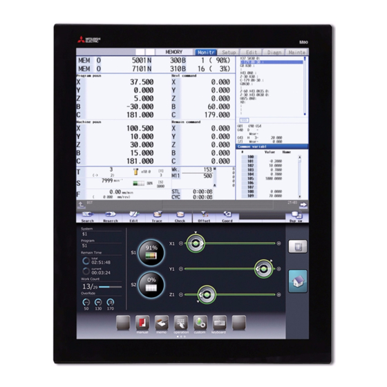
Mitsubishi Electric M800 Series Manual (749 pages)
Brand:
Mitsubishi Electric
| Category:
Touch Panel
| Size: 3.84 MB
Table of Contents
Manual List
3
Manuals for Mtbs (Drive Section)
4
Manuals for Mtbs (NC)
4
Manuals for Mtbs (Others)
5
Reference Manual for Mtbs
6
For Safe Use
8
Precautions for Safety
8
Caution
9
Disposal
10
Table of Contents
16
Alarm
18
1 Operation Errors (M)
20
Aux Ax Dog Overrun
21
Aux Ax R-Pnt Direction Illegal
21
Aux Ax External Interlock
21
Aux Ax Internal Interlock
21
Some Ax Does Not Pass Z Phase
22
R-Pnt Direction Illegal
22
External Interlock Axis Exists
22
Internal Interlock Axis Exists
22
S/W Stroke End Axis Exists
23
Chuck/Tailstock Stroke End Ax
23
Ref Point Return No. Invalid
23
Illegal Op in MID Pt Sg Block
23
R-Pnt Ret Invld at Abs Pos Alm
24
R-Pnt Ret Invld at Zero Pt Ini
24
High-Accuracy Skip Disabled
24
Hi-Ac Skip Coord Retrieval Err
24
Chopping Axis R-Pnt Incomplete
25
Synchronous Error Excessive
25
No Spindle Select Signal
25
No Spindle Serial Connection
25
Wait for Tap Retract
26
Handle Ratio too Large
26
R-Pos Offset Value Illegal
26
R-Pos Scan Distance Exceeded
26
Illegal Op in Dia/Rad Select
27
No Operation Mode
27
Cutting Override Zero
27
External Feed Rate Zero
27
F 1-Digit Feed Rate Zero
28
Spindle Stop
28
Handle Feed Ax No. Illegal
28
Spindle Rotation Speed over
28
Restart Switch on
29
Program Check Mode
29
Cycle St. in Buffer Correct
29
In Reset Process
29
In Synchronous Correction Mode
30
No Synchronous Control Option
30
Computer Link B Not Possible
30
X/Z Axes Simultaneous Prohibit
30
PLC Interruption Impossible
31
Restart Posn Return Disabled
31
Zero Point Return Interruption
31
Excessive No. of Reverse Block
31
Unable to Start Automatic Mode
32
Tool Data Sorting in Progress
32
Tolerance Control Invalid
32
Ill Manualmode Select in 3Dcnv
32
Chopping Override Zero
33
Command Axis Chopping Axis
33
Bottom Dead Center Pos. Zero
33
Chopping Disable for Handle Ax
33
No Speed Set out of Soft Limit
34
Aux Ax R-Pnt Ret Incomplete
34
Aux Abs Position Initializing
34
Aux Ax Abs Position Error
34
Aux Ax Torque Limit Value Zero
35
Ill. Op During T Tip Control
35
Illegal Op in Spline Interpol2
35
Illegal OP in Tilted Face Cut
35
Rotary Axis para Unswitchable
36
Interference Check Invalidated
36
Machine Interference 1
36
Tool Interfere. Check Disabled
36
Too Many Simul. Control Axes
37
Changing Prg Format Disabled
37
Multi Ax for 3D Manual Feed
37
3D Manual Feed Coord Sys Err
37
Rot Center Err Comp Excessive
38
Unable to Start Measuring Err
38
Invalid Op Mode in Err Measure
38
Machining Surface Operation Disabled
38
No Spec: Spatial Error Comp
39
Spatial Error Comp Excessive
39
Auto Backlash Adjust Illegal
39
Operating Auto Backlash Adjust
39
N/A During High-Cycle Sampling
40
Invalid CMD During Param Write
40
SP Orient. Z Detection Error
40
Illegal Movement Command During Superimposition
40
Superimposition Command Illegal
41
G114.N Command Illegal
41
Spindle In-Use by Synchro Tap
41
GB Spindle Synchro Signal off
41
GB SP Sync:phase Mem Sgnl Ilgl
42
GB SP Sync:phase Set Sgnl Ilgl
42
GB SP Sync:z Phase Not Pass
42
Cmnd Impsbl in Spindle Rtry Ax
42
Thread Recutting Impossible
43
Thread Recutting Data Illegal
43
Variable Speed Thread Disabled
43
Synchronization Mismatch
43
Sp-Sp Polygon Cut Interlock
44
Mixed Sync Ctrl Prmtr Illegal
44
Mixed Sync Ctrl Disable Modal
44
Synchro Ctrl Setting Disable
44
Move Cmnd Invld to Synchro Ax
45
No Spindle Speed Clamp
45
Cont Ax Superimpos II Prm Illg
45
Sync Error Btwn Part Systems
45
Intrf Check Across Sys: Alarm
46
Interfe Chk 0Pt Return Incomp
46
Feed-Forward Control Disabled
46
Superimposition Axis Param Err
46
Cross Control Axis Exists
47
Arbitrary Ax Superimp. Sys Err
47
Spindle Speed Fluctuation
47
Sp Synchro Phase Calc Illegal
47
Sub Part System I Call Error
48
Sub Part System II Start Error
48
Constant Surface Speed Rdndnt
48
Constant Torque Disabled
48
Droop Cancel Disabled
49
Cmnd Disabled in Droop Cancel
49
SP Equivalent Load Factor over
49
Differential Tap Cmnd Disabled
49
Spindle Sync Cancel Error
50
GB SP Sync:cancel Sgnl Illegal
50
GB SP Sync Runs Independently
50
Cmds Illegal in Spindle Synchr
50
Prog Check: Machine Posn Error
51
NC/PLC Axis Switch Illegal
51
No Spec: Multi Axis Synch Ctrl
51
Multiple Secondary Ax Selected
51
Interference Data Unspecified
52
Interf. 3D Objects Count Error
52
Interfere Check III: Time over
52
Interfere: Control Axis Error
52
Interfere:2 Rot Axes Object er
53
Interfere:1 Rot Axis Object er
53
Interf. Selection: Offset over
53
Interf:rot Objects Comb. Error
53
2 Stop Codes (T)
54
Axis in Motion
55
NC Not Ready
55
Reset Signal on
55
Auto Operation Pause Signal on
55
Operation Mode Duplicated
56
Operation Mode Changed
56
Tape Search Execution
56
Cycle Start Prohibit
56
In Absolute Position Alarm
57
In Abs Posn Initial Setting
57
In Manual Measurement
57
Sub Part Sys I Mode Is Active
57
Cycle Start Prohibit (OP Error)
58
Cycle Start Prohibit(SBT Warn)
58
Cycle St. Prohibit (Term Exp'D)
58
Cycle Start Disabled (in SBT)
58
Block Stop Cmnd in User Macro
60
MDI Completed
60
Block Start Interlock
60
Cutting Blck Start Interlock
60
Collation Stop
61
Fin Wait
61
3 Servo/Spindle Alarms (S)
62
Servo Errors (S01/S03/S04)
63
Drive Unit Alarm
64
Encoder Alarm (Servo Drive Unit)
68
Encoder Alarm (Spindle Drive Unit)
69
Dual Signal Error (4D)
70
Power Supply Alarm
72
Initial Parameter Errors (S02)
73
Safety Function Errors (S05)
75
Parameter Errors (S51)
76
Servo Warnings (S52)
77
Drive Unit Warning
78
Dual Signal Warning (A4)
78
Power Supply Warning
79
Safety Function Warnings (S53)
80
4 MCP Alarms (Y)
82
System Alm: Process Time over
83
SV Commu Er: Data ID Error
83
SV Commu Er: Recv Frame No.
83
SV Commu Er: Commu Error
83
SV Commu Er: Connect Error
84
SV Commu Er: Safe Posn FB Err
84
SV Commu er : Init Commu Error
84
SV Commu Er: Node Detect Err
85
SV Commu Er: Commu Not Support
85
Drive Unit Unequipped
85
Mcp_No Setting Error
87
Too Many Drive Units Connected
88
Too Many Axisno Connected
88
No Commu. with Axis Drv Unit
88
No Commu. with Sp Drv Unit
88
RIO Connection Error
89
Parameter Compare Error
89
Sfty Obsrvation: CMD Spd Err
89
Sfty Obsrvation: FB Pos Err
89
Sfty Obsrvation: FB Speed Err
90
Door Signal: Input Mismatch
90
No Speed Observation Mode in Door Open
90
Speed Obsv: para Incompatible
90
Contactor Welding Detected
91
No Spec: Safety Observation
91
SDIO Connector Input Volt Err
91
Device Setting Illegal
92
Contactor Operation Abnormal
92
STO Function Operation Illegal
93
STO Function Illegal at Pwr on
93
Dual Signal: Parameter Setting Error
93
Safety Observation: Parameter Memory Error
93
Parameter G0T1 Illegal
94
Parameter G1T1 Illegal
94
Parameter Grid Space Illegal
94
Parameter Stapt1-4 Illegal
94
OMR-II Parameter Error
95
PLC Indexing Stroke Length Err
95
Hi-Acc Time Const Unextendable
95
Superimpos Linear G0 Error
95
Unable to Alloc. Hi-Acc Buffer
96
Too Many Hi-Speed/Accu Systems
96
Parameter G0Tl_2 Illegal
96
Parameter G0T1_2 Illegal
96
Machine Group No. Discrepancy
97
M-Group Alarm Stop Disabled
97
Basic Axes I, J, K Error
97
Values of PC1/PC2 too Large
97
5 System Alarms (Z)
98
System Error
99
CC-L IE F Communication Error
99
CC-L IE F Parameter Error
99
CC-Link IE F H/W Test Status
99
Network Expansion Card Error
100
PROFIBUS Parameter Error
100
Axis Ex-Adr. Error
100
Unable to Start Safe Spd Clamp
100
Ethernet/Ip Communication Err
101
Socket Open Error(Socket)
101
Socket Bind Error(Bind)
101
Connection Wait Queue Error(Listen)
101
Devicenet Error
102
Direct Socket Connection Error
102
Direct Socket Receive Error
102
Direct Socket Send Error
102
Ecomonitorlight Comm. Error
103
Ecomonitorlight Qty Discrepant
103
Insulation Deterioration Wrn
103
E-Mail Send Error
103
E2PROM Error
104
Battery Fault
104
CNC Overheat
104
RIO Communication Stop
105
System Warning
105
ROM Write Not Completed
105
Acc/Dec Time Cnst too Large
106
Fieldbus Communication Error
106
Valid Term Soon to be Expired
106
Valid Term Has Been Expired
106
External Link Error
107
3D Machine Interference/No Machine Model
108
3D Machine Interference/Machine Model Illegal
108
3D Machine Interference Check Load Excess
108
3D Machine Interference Check Error
108
No Display Conn. to Panel I/O
109
Power on Sequence Error
109
Power off Sequence Error
109
Display Unit Shutoff Timeout
109
Overvoltage Detection Alarm
110
Memory ECC Error
110
6 Absolute Position Detection System Alarms (Z7*)
112
Abs Posn Base Set Incomplete
113
Absolute Position Lost
113
Abs Posn Param Changed
113
Abs Posn Initial Set Illegal
113
Abs Posn Param Restored
114
Abs Posn Data Lost
114
Abs Posn Error(Servo Alm 25)
114
Abs Posn Error(Servo Alm E3)
114
Absencoder: Commu Error
115
Absencoder: Abs Data Changed
115
Absencoder: Serial Data Error
115
Absencoder: Abs/Inc Posn Diffr
115
Battery for Abs Data Fault
116
7 Distance-Coded Reference Scale Errors (Z8*)
118
Basic Position Lost
119
Basic Position Restore
119
No Spec: Distance-Coded Scale
119
R-Pos Adjustment Data Lost
119
8 Emergency Stop Alarms (EMG)
120
Emergency Stop
121
9 Computer Link Errors (L)
124
Timeout Error
125
Host er Signal off
125
Parity H Error
125
Parity V Error
125
10 User PLC Alarms (U)
126
No User PLC
127
Illegal PLC
127
11 Network Service Errors (N)
136
Modem Initial Error
137
Redial over
137
TEL Unconnect
137
Invalid Net Communication
137
Password Error
138
Customer Number Error
138
Storage Capacity over
138
File Deletion Error
138
12 Program Errors (P)
140
No. of Simultaneous Axes over
141
Illegal Axis Address
141
Division Error
141
Not Accept Command
141
Illegal Address
142
Format Error
142
Illegal G Code
142
Setting Value Range over
142
No Specifications
143
Pre-Read Block Error
143
G Code Combination Error
143
Restart Pos Return Incomplete
143
No Spec: Unidirectional Posit.
144
No F Command
144
No Spec: High Speed Mode 3
144
F Value Is Exceeding the Limit
144
No Spec: Herical Cutting
145
No Spec: Spiral Cutting
145
Can't Calculate 3DIM Arc
145
3DIM Arc Illegal
145
Plane Select During Figure Rot
146
Plane Selected While Coord Rot
146
Plane Selected While R Compen
146
Illegal Plane Select
146
No Spec: High-Accuracy Control
147
No Spec: Inverse Time Feed
147
G93 Mode Error
147
Invalid Cmnd in High-Accuracy
147
No Spec: Cnst Surface Ctrl G96
148
Spindle Rotation Speed S=0
148
Illegal P-No. G96
148
G96 Clamp Err.
148
Radius Compen During Arc Mode
149
No Intersection
149
Compensation Interference
149
No Spec: 3D Compensation
149
Illegal Tip Point
150
No Spec: 3D Tool R Comp
150
Disable CMD in 3D Tool R Comp
150
3D Tool R Comp Is Disabled
150
G10 P Number Error
151
No Spec:comp Input by Prog G11
151
Tool Life Count Active
151
Tool Life Data Entry over
151
Synchronous Tap Error
152
No Pitch/Thread Number
152
Pitch/Thread Number Error
152
No Spec: Sync Tapping Cycle
152
Tool Selection Is Incorrect
153
No Spec: MRC Cycle
153
Program Error (MRC)
153
Block over (MRC)
153
No Spec: Special Fixed Cycle
154
No. of Special Fixed Holes = 0
154
G36 Angle Error
154
G12/G13 Radius Error
154
Program Editing
155
No Spec: Variable Commands
155
No Variable No.
155
Can't Use Variables
155
No Spec: Figure Rotation
156
Figure Rotation Overlapped
156
Coord Rotate in Fig. Rotation
156
No Spec: Coordinates Rotation
156
Macro Call Nesting over
157
Macro Argument over
157
Illegal G67 Command
157
Macro Alarm Message
157
If-Endif MMC.
158
IF Sentence Error
158
WHILE Sentence Error
158
SETVN Sentence Error
158
Address-A Error
159
G200-G202 Cmnd in Tape
159
Variable Name Illegal
159
Variable Name Duplicated
159
Facing T-Post MR Illegal
160
No Spec: Corner R/C
160
No Spec: Arc R/C
160
No Corner Movement
160
No Spec: Geometric Arc
161
Inc Value in 2Nd Block (GEOMT)
161
No Linear Move Command (GEOMT)
161
Illegal Address (GEOMT)
161
Illegal Modal G111
162
No Spec: Axis Name Switch
162
No Spec: para Input by Program
162
Parameter Input Error
162
R-Navi Input Error
163
R-Pnt Return Incomplete
163
No Spec: 2,3,4Th R-Point Ret
163
No Spec: Start Position Return
163
G29 and M Commands in a Block
164
G52 Invalid During G54.1
164
No Spec: Chuck Barrier
164
No Spec: Stroke Chk Bef Travel
164
No Spec: Milling
165
Illegal G Code (Mill)
165
Illegal Axis (Mill)
165
R-Pnt Ret Incomplete (Mill)
165
Illegal Modal (Mill)
166
Milling Error
166
Cross (G110) Impossible
167
Illegal G110 Axis
167
Synchronization M Code Error
167
Control Axis Superimposition/Designated Axis Illegal
167
Illegal Synchronization Axis
168
No Spec: Wk Instl Err Cmp
168
Invld CMD in Wk Instl Err Cmp
168
Wk Instl Err Cmp CMD Invalid
168
Invld Manual Interrupt in G6.2
169
Invalid Restart During G06.2
169
Fairing Changeover Disabled
169
Skip Axis Illegal
169
TLM Illegal Axis
170
T & TLM Command in a Block
170
T Cmnd Not Found before TLM
170
TLM Illegal Signal
170
Exponential Function Error
171
Sub Sys Identification # Error
171
Other G Code in Sub Sys Block
171
Illegal Mode (Sub Part System)
171
PLC Device too Much
172
Illegal Command Value
172
Dia/Rad Selection CMD Invalid
172
Invld CMD in Dia/Rad Selection
172
Proceed of Prog Check Disabled
173
No Spec: Normal Line Control
173
Normal Line Control Axis G92
173
Normal Line Control Axis Error
173
Illegal Addr in 3D Coord Blk
174
Travel CMD Error in 3Dconvert
174
End Point Err in 3D Conversion
174
No Spec: Tool Axis Compen
174
Invalid T Tip Control Command
175
Invalid Cmnd During T Tip Ctrl
175
Tool Posture Command Illegal
175
No Spec: Tilt Face Machining
175
Inclined Face Coord Illegal
176
G68.2P10 Surface Not Defined
176
Tool Axis dir Ctrl Cmp Amt 0
176
Tool Axis dir Ctrl Axis Illeg
176
Illegal Direct Cmnd Mode Cmnd
177
PREPRO Error
177
13 Smart Safety Observation Alarm (V)
178
Smart Safety Observation Error (V01/V02/V03/V04/V05/V06/V07)
179
Safety Watchdog Error
179
Cross-Check Error
179
Safe Sys Internal Process Err
179
NC-DRV Initial Safe Comm Error
180
Safe IO Init. Process Timeout
180
Encoder Error
180
NC-DRV Safe Communication Err
180
Slave Station Data Compare Err
181
Output off Check Error
181
Output Signal Cross-Check Err
182
Transmission Cross-Check Error
182
Reception Cross-Check Error
182
Host Station Comm. Error 1
183
Host Station Comm. Error 2
183
Drv Safe Receive Crosscheck er
183
User Safety Sequence 1 Error
183
User Safety Sequence 2 Error
184
Output Sig. Cross Check Error
184
Safety Observation & Smart both on
184
Safety IO Device Unconnectable
184
Safe IO Disabled: Connect Err
185
Safe IO Disabled: no Safe I/Os
185
Safety PLC Is Not yet Written
185
NC-DRV Safety Comm. Disabled
185
EMG Stop Signal Device Illegal
186
Safe IO Assign para Setting er
186
Safety I/O Param Inconsistent
186
SLS Speed Error
186
SLS Deceleration Error
187
SLP Position Error
187
SOS Speed Error
187
SOS Position Deviation Error
187
SOS Travel Distance Error
188
SS1 Deceleration Error
188
SS2 Deceleration Error
188
Safety External EMG Stop Is on
188
Smart Safety Observation Warning (V50/V51/V52/V53/V54)
189
SSM Hysteresis Setting Error
189
Safe Absol. Posn Unestablished
189
SBT Start Disabled
189
SBT Warning 4
190
SBT Warning 5
190
SBT Warning 6
190
PLC Safety Stop Is Active
190
Warning on 24Hr Continuous on
191
Simple Test Mode Is Active
191
14 Multi CPU Errors (A) [C80]
192
Power Shutoff
193
ROM Write Count Error
193
Default Gateway/Gw IP Address Error
193
Own Node Port Number Error
193
Socket Comm. Response Send Error
194
TCP Connection Timeout
194
IP Address Error
194
Connection Number Acquisition Error
194
Parameter
194
TCP/IP Send Failed
195
Unsend Data Send Error
195
Module Moderate Error
195
Parameter
195
Multiple CPU Synchronization Processing Error
196
Receive Queue Full
196
Receive Processing Error
196
Transient Data Error
196
Parameter
196
Module Configuration Error
197
Parameter
197
CPU Module Configuration Error
198
Parameter
198
Base Unit a Configuration Error
199
Inter-Module Synch Configure Error
199
Parameter
199
Module Unrecognized
200
IP Address Duplication Error
200
Invalid File
200
File Specification Error
200
Parameter
200
Parameter a Error
201
Parameter Error (Module)
202
Parameter Error (Network)
202
Parameter
203
Parameter Verification Error
204
Security Key Authentication Error
204
Remote a Password Setting Error
204
Module Verification Error
205
Fuse Blown Error
205
Module Major Error
205
Parameter
205
Another CPU Module Major Error
206
Multiple CPU Error
206
Parameter
206
System Bus Error
207
Parameter
207
Parameter
208
WDT Error
209
Invalid Interrupt
209
Inter-Module Synch Signal Error
209
Parameter
209
Multiple CPU Synch Signal Error
210
Boot Function Execution Error
210
Parameter
210
Pointer Setting Error
211
Interrupt Pointer Setting Error
211
Parameter
211
Hardware Failure
212
Parameter
212
Parameter
213
Parameter
214
Parameter
215
Parameter
216
Parameter
217
15 User Parameters
218
Machining Parameters
219
G76G78In-Posn Wdt.
224
Turning Cycle Mode
224
3-D CMP (for M System Only)
224
SCALING P (for M System Only)
224
Gcode Rotat (for L System Only)
225
G68.1 R INC (for L System Only)
225
Coord Rot Plane (H)
225
Coord Rot Plane (V)
225
Coord Rot Angle
226
Tool Length
226
Tool Dia
226
TLM L Meas Axis
227
TLM D Meas Axis
227
Skip Coord. Switch (for M System Only)
227
Thrdrecut Lead Ax
227
WE Meas. Wk Coord
228
WE Meas. Ext Wk no
228
WE Mea. Wk X-Width
228
WE Mea. Wk Y-Width
228
Sensor T L Comp no
229
Tolerance Ctrl on
229
Smth Corn Spd Coef
229
Smoothing Range
229
PRG Coord Rot Type
230
Tap Feedrate Limit
230
Manual Fcmd2 Clamp
230
EOR Disable
230
Corner Check Width
231
Ana-Tap-Voltage1
231
Ana-Tap-Voltage2
231
Stylus Sphere Dia.
231
Sensor Over-Travel
232
Rotary Ax Drawing
232
Hob Retract on at Alarm
232
Hob Retract Acceleration Deceleration off
232
Arc Inside Min Ovr (for M System Only)
233
Timing Sync System
233
Arc Inside Ovr on (for M System Only)
233
Arc Inside Ovr Typ (for M System Only)
233
Manualb Std F1
234
Manualb Std R2
234
Manualb Std F2
234
Fixed Cycle Parameters
235
G73N (for M System Only)
235
G83 N
235
CDZ-VALE (for L System Only)
235
G73 W
236
G73 R
236
G74 Retract
236
G76 Last-D
236
Control Parameters 1
237
Pb_G90
238
Rstvci
238
Pwrvcl
238
Autorp
238
R COMP Select
239
Host Link
239
G71/G72 Pocket
239
Milling Radius
239
Milling Init G19
240
G83/87 Rapid
240
Font Selection
240
Screen Capture
240
Keep G43 MDL M-REF
241
H-Spd Retract on
241
Mirr Img at Reset
241
Check Scode in G84
241
High Speed/Accu 3
242
G53.6 Block Stop
242
Intrctv Macro Call
242
Email Send Disable
242
Validate F1 Digit
243
Sub-Pro Interrupt
243
Fine Thread Cut E
243
Radius Comp Type B (M System) / Nose R Comp Type B (L System)
243
Control Parameters 2
244
G00Drn
245
G0Lntp
245
I_G611
245
Hold Intr Amount
245
I/O Parameters [M8]
246
Data in Port
246
Data in Dev.
246
Tape Mode Port
246
Plc In/Out Port
247
Plc In/Out Dev.
247
Remote Prg in Port
247
Remote Prg in Dev.
247
Macro Print File
248
Dev0 Device Name
248
Dev0 Baud Rate
248
Dev0 Stop Bit
248
Dev0 Even Parity
249
Dev0 Chr. Length
249
Dev0 Terminatr Typ
249
Dev0 Hand Shake
249
Dev0 Feed Chr.
250
Dev0 Parity V
250
DEV0 TIME-OUT (Sec)
250
Dev0 Dr off
250
Dev0 Eia Code
251
Dev0 Eia Code !
252
Dev1 Device Name
252
Dev1 Baud Rate
252
Dev1 Stop Bit
252
Dev1 Chr. Length
253
Dev1 Terminatr Typ
253
Dev1 Hand Shake
253
Dev1 DC Code Prty
253
Dev1 Feed Chr.
254
Dev1 Parity V
254
Dev1 Dr off
254
Dev1 Data Ascii
254
Dev2 Device Name
256
Dev2 Baud Rate
256
Dev2 Stop Bit
256
Dev2 Parity Check
256
Dev2 Chr. Length
257
Dev2 Terminatr Typ
257
Dev2 Hand Shake
257
Dev2 DC Code Prty
257
Dev2 Feed Chr.
258
Dev2 Parity V
258
Dev2 Dr off
258
Dev2 Data Ascii
258
Dev2 Eia Code !
260
Dev3 Device Name
260
Dev3 Baud Rate
260
Dev3 Stop Bit
260
Dev3 Chr. Length
261
Dev3 Terminatr Typ
261
Dev3 Hand Shake
261
Dev3 DC Code Prty
261
Dev3 Parity V
262
Dev3 Dr off
262
Dev3 Data Ascii
262
Dev3 Input Type
262
Dev4 Device Name
264
Dev4 Baud Rate
264
Dev4 Stop Bit
264
Dev4 Parity Check
264
Dev4 Chr. Length
265
Dev4 Terminatr Typ
265
Dev4 Hand Shake
265
Dev4 DC Code Prty
265
Dev4 Parity V
266
Dev4 Dr off
266
Dev4 Data Ascii
266
Dev4 Input Type
266
Axis Parameters
268
Ax. Release
268
Ot-Check off
268
Ot-Check-Cancel
268
Ot Inside
269
Mirr. Image
269
Rotation Axis Type
269
TLM Std Length
270
Type in G28 Return
270
Check Start Point
270
Dir CMD Retrct Amt
270
Wk Coord at R Ret.
271
Wk Position Check
271
Machine Posn Check
271
Ethernet Parameters
272
Global IP Address
272
Global Subnet Mask
272
Global Gateway
272
NET3 IP Address
273
NET4 IP Address
273
Local Time Compen
273
Intra IP Address
273
IP Addr Auto Set
274
Host No.
274
Host1 Host Name
274
Host1 User Name
274
Host1 Directory
275
Host1 Host Type
275
Host 1 Wrd Pos: Name
275
Host 1 Wrd Pos: Size
275
Host 1 Wrd Pos: dir
276
Host 1 Wrd Pos: Cmnt
276
Host 1 Wrd Num: Cmnt
276
Host 1 no Total Siz
276
Host2 Host Name
277
Host2 User Name
277
Host2 Password
277
Host2 Directory
277
Host2 Host Type
278
Host 2 Wrd Pos: Name
278
Host 2 Wrd Pos: Size
278
Host 2 Wrd Pos: dir
278
Host 2 Wrd Pos: Cmnt
279
Host 2 Wrd Num: Cmnt
279
Host 2 no Total Siz
279
Host3 Host Name
279
Host3 User Name
280
Host3 Password
280
Host3 Directory
280
Host3 Host Type
280
Host 3 Wrd Pos: Name
281
Host 3 Wrd Pos: Size
281
Host 3 Wrd Pos: dir
281
Host 3 Wrd Pos: Cmnt
281
Host 3 Wrd Num: Cmnt
282
Host 3 no Total Siz
282
Host4 Host Name
282
Host4 User Name
282
Host4 Directory
283
Host4 Host Type
283
Host 4 Wrd Pos: Name
283
Host 4 Wrd Pos: Size
283
Host 4 Wrd Pos: dir
284
Host 4 Wrd Pos: Cmnt
284
Host 4 Wrd Num: Cmnt
284
Host 4 no Total Siz
284
MES-IF DB Port no
285
MES-IF DB Timeout
285
MES-IF DB Type
285
MES-IF DB Name
285
MES-IF DB Table
286
PC IP Address
286
Computer Link Parameters [M8]
287
Baud Rate
287
Stop Bit
287
Parity Effective
287
Hand Shake
288
Time-Out Set
288
Data Code
288
Start Code
289
Ctrl. Code out
289
Ctrl. Interval
289
Wait Time
289
Subprogram Storage Location Parameters [M8]
291
Subpro Stor D0: Dev
291
Subpro Stor D0: dir
291
Subpro Stor D1: Dev
291
Subbro Stor D2: Dev
292
Subbro Stor D3: Dev
292
Subpro Stor D3: dir
292
Subbro Stor D4: Dev
293
Subpro Stor D4: dir
293
Subpro Srch Odr D0 to D4
293
Barrier Data (for L System Only)
294
High-Accuracy Control Parameters
297
Cireft
297
G0Bdcc
297
G1Bf
297
R Comp
299
DCC Angle
300
Comp_Change
300
Corner Comp
301
Curve Comp
301
Spline on
301
Minute Lengs
302
Fairing on
302
Accclamp on (for M System Only)
302
Cordecjudge (for M System Only)
302
SSS on (for M System Only)
303
Stdlength (for M System Only)
303
Clampcoeff (for M System Only)
303
Stepleng (for M System Only)
303
Arc Clamp Spd Coef
304
Jerk_Filtg1
304
Jerk_Filtg0
304
Eachaxacccntrl
304
High-Accuracy Control Axis Parameters
306
G1Bfx
307
G1Btlx
307
Compx
307
Operation Parameters
308
Counter Type 1
308
Aut/Manual Switch
312
Edit Undo
312
NAVI-Message on
312
NAVI Operate Type
313
Touch Panel Sense
313
Auto Top Search
313
Auto Backup Day 1
313
Auto Backup Day 3
314
Auto Backup Day 4
314
Auto Backup Device
314
3D Tool Ofs Select
315
Mass Edit Select
315
T-Reg-Dup Check
315
Hide Edit-IO Menu
315
SP on 1St Part Sys
316
SP on 2Nd Part Sys
316
SP on 3Rd Part Sys
316
SP on 4Th Part Sys
317
Disable=Input:comp
317
Disable=Input:var
317
Display/Set Limit
317
Disable Wear Comp
318
W Coord Confirm
318
File Sort Volume
318
Edit-Not Show Prg
318
ABS/INC for T-Ofs
319
No Tab Counter Sw.
320
2$ Disp Switch Typ
320
Initial Type
320
Init Axis Pair
321
User Key Type
321
T Meas (L)-Simple
321
SP on 5Th Part Sys
321
SP on 6Th Part Sys
322
SP on 7Th Part Sys
322
SP on 8Th Part Sys
322
Edit: ins or OVR
324
Delete Key Action
324
Tool Shape Radius
324
Tool Offset Type 1
325
Alarm Window on
326
T Code Offset Disp
326
Selective Display
326
Simple PLC Switch
327
No. Search Process
327
Menu Animation off
327
Touch Op Noise Res
327
R-Navi Graphic dir
328
Ncmemory Date Disp
328
Edit-Up/Down Keys
329
Interactive Cycle
329
Cycle Switch
330
Cycle Highlight
330
Touchop Longtaptim
330
Simple Program on
330
Hi-Speed Grph Chck
331
Finish Shape View
331
Simul Edit - View
331
Restrain Vncserver
331
VNC Color Depth
332
VNC Transmit Cycle
332
Edit-Upward Search
332
Machining Condition Selection Parameters
333
MINUTE LENGS (for M System Only)
338
Fairing on (for M System Only)
338
Corjudgel (for M System Only)
338
P1-Sfiltg1
339
P1-Sfilt2
339
P1-Rcomp
339
P1-Cor_Comp
339
P1-Spcanag
340
P1-Distth1
340
P1-Distth2
340
P2-Step_Length
344
P2-Tolerance
344
P2-G1Bf
344
P2-Sfilt2_Tol
344
Menu Selection Parameters
348
Monitr Main Menu 1 to 30
348
Setup Main Menu 1 to 30
352
Edit Main Menu 1 to 30
355
Tolerance Parameters[M8]
357
Advertisement
Mitsubishi Electric M800 Series Maintenance Manual (212 pages)
Brand:
Mitsubishi Electric
| Category:
Control Systems
| Size: 17.51 MB
Table of Contents
Table of Contents
26
1 System Basic Configuration
28
System Basic Configuration Drawing
29
General Connection Diagram
31
General Connection Diagram [M800W]
31
General Connection Diagram [M80W]
34
General Connection Diagram [M800S]
37
General Connection Diagram [M80]
38
General Connection Diagram [E80]
40
How to Check the System Configuration
41
System Configuration Screen
41
Option Display Screen
44
Each Unit Status Display
45
Control Unit
45
Personal Computer Unit
48
Operation Panel I/O Unit
49
Remote I/O Unit
52
Communication Expansion Unit
54
CC-Link Expansion Unit
54
PROFIBUS-DP Expansion Unit
55
CC-Link IE Field
56
Ethernet/Ip
57
7-Segment Leds on the Control Unit
58
Normal State Display
58
Error Display at NC Startup
58
Display When an Alarm Occurs
59
2 Daily Maintenance and Periodic Maintenance
68
Daily Maintenance
70
Touchscreen
70
Escutcheon
70
Periodic Maintenance
71
List of Durable Parts
71
List of Replacing Parts
71
Durable Parts Replacement
72
Control Unit Battery
72
Personal Computer Unit Cooling Fan
74
Replacing Fuse
75
3 Maintenance of the Drive Unit
78
Periodic Inspections
79
Durable Parts
80
Adding and Replacing Units and Parts
81
MDS-E/EH Series
81
Replacing the Drive Unit
81
Replacing the Unit Fan
82
Replacing the Battery
84
MDS-EJ/EJH Series
87
Replacing the Drive Unit
87
Replacing the Unit Fan
87
Replacing the Battery
93
MDS-EM/EMH Series
96
Replacing the Drive Unit
96
Replacing the Fan Unit
97
Replacing the Battery
98
4 Failure Diagnosis
102
Introduction
103
Failure Diagnosis Procedure
103
Diagnosis Based on the Alarm
104
How to Check the Alarm Information
104
Alarm History
106
Alarm Message Details
108
Diagnosis Based on the I/F Diagnosis Screen
109
I/F Diagnosis Screen
109
Displaying the PLC Device Data
111
Carrying out Modal Output
112
Carrying out One-Shot Output
113
List of Devices for PLC Uses
114
Diagnosis Based on the Self Diagnosis Screen
115
Self Diagnosis Screen
115
Diagnosis Based on the Data Sampling Screen
120
Diagnosis Based on the Drive Monitor Screen
121
Drive Monitor Screen (Servo Unit)
121
Drive Monitor Screen (Spindle Unit)
126
Drive Monitor Screen (Power Supply Unit)
131
Drive Monitor Screen (Synchronous Error)
133
Clearing the Alarm History on Drive Monitor Screen
134
NC Memory Diagnosis Screen
135
Safety Observation Screen
137
Safety Observation Screen (Configuration Diagnosis)
137
Safety Observation Screen (Signal Monitor)
139
Safety Observation Screen (Drive Monitor)
141
Safety Observation Screen (Version Display)
144
Servo Diagnosis Screen
145
Diagnosis Data Collection Setting
148
Starting the Data Collection
150
Stopping the Data Collection
150
Clearing the Collected Data
151
Referring to the Collected Data
151
Display Delay Function for Communication Errors and Servo/Spindle Alarms
154
Application Error Detection
155
IP Address Resetting Procedure at Disabled Network Communication [M800W/M80W Series Only]
156
Connectable Control Unit IP Address List Screen
156
Resetting Procedure
157
Message
158
Field Network Diagnostics Function
159
Diagnosis Procedure
160
Statistical Information in Packet Transmission and Reception
160
Protocol-Specific Information
162
Diagnosis Command
163
Clearing Statistical Information of Packet Transmission and Reception
163
Error Code List
164
Mitsubishi Electric M800 Series Manual (18 pages)
Brand:
Mitsubishi Electric
| Category:
Recording Equipment
| Size: 5 MB
Table of Contents
Advanced Design
3
System Configurations
6
Specifications
12
Drive System
13
Software Tools
14
Global Service Network
15
Warranty
16
Advertisement
Advertisement
Related Products
Mitsubishi Electric MC 200
Mitsubishi Electric M80 Series
Mitsubishi Electric M800W Series
Mitsubishi Electric M800S Series
Mitsubishi Electric M800VW Series
Mitsubishi Electric M800VS Series
Mitsubishi Electric M800V Series
Mitsubishi Electric M80W Series
Mitsubishi Electric M80 TypeB
Mitsubishi Electric M80VW Series
Mitsubishi Electric Categories
Air Conditioner
Controller
Projector
Inverter
Heat Pump
More Mitsubishi Electric Manuals
Login
Sign In
OR
Sign in with Facebook
Sign in with Google
Upload manual
Upload from disk
Upload from URL